
Motors Automobile Parts User Manual


ENGINE <6A1> -
Cylinder Head Gasket
11B-25
REMOVAL SERVICE POINT
A
A
"
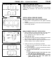
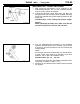
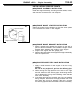
CYLINDER HEAD BOLT REMOVAL
Loosen the bolts in 2 or 3 steps in order of the numbers
shown in the illustration, and remove the cylinder head
assembly.
INSTALLATION SERVICE POINTS
"
A
A
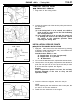
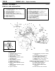
CYLINDER HEAD GASKET INSTALLATION
1. Wipe off all oil a n d grease from the gasket mounting
surface.
2. Install the gasket to the cylinder block with the identification
mark facing upwards.
"
B
A
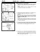
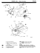
CYLINDER HEAD BOLT INSTALLATION
1. When installing the cylinder head bolts, the length below
the head of the bolts should be within the limit.
If it is outside the limit, replace th e bolts.
Limit (A): 96.4 mm
2. The head bolt washer should be installed with the burred
side caused by tapping out facing upwards.
3. Apply a small amount of engine oil to the thread section
and the washer of the cylinder head bolt.
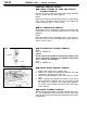
4. Install the bolts by the following procedure.
(1) Tighten the bolts to 20 Nm in the sequence shown
in the illustration.
(2) From the position in (1) above, turn each bolt a further
120_ in the same sequence.
(3) Turn each bolt a further 120_ in the same sequence.
Caution
1) If the tightening angle is less than 120
_
, that
bolt will not be sufficiently tight.
2) If a bolt is tightened by more than the specified
angle, loosen the bolts and repeat the
procedure from step (1).
Front of
engine
Intake side
<Front bank side>
Exhaust side
<Rear bank side>
Exhaust side
Identification mark
Head bolt
Burred side
Head bolt
washer
(Engine
oil)
Cylinder
head
A
Front of
engine
<Front bank side>
Exhaust side
Exhaust side
Intake side
<Rear bank side>