1A-0-1 ENGINE 6G7 SERIES CONTENTS GENERAL INFORMATION . . . . . . . . . . . . . . . . . . . . . . . . . . . . . . . . . . . . . . . . . . . 11A-0-3 1. SPECIFICATIONS . . . . . . . . . . . . . . . . . . . . . . . . . . . . . . . . . . . . . . . . . . . . . . . 11A-1-1 SERVICE SPECIFICATIONS . . . . . . . . . . . . . . . . . . . . . . . . . . . . . . . . . . 11A-1-1 REWORK DIMENSIONS . . . . . . . . . . . . . . . . . . . . . . . . . . . . . . . . . . . . . . . 11A-1-2 TORQUE SPECIFICATIONS . . . . . . . .
11A-0-2 NOTES E Mitsubishi Motors Corporation Dec.
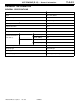
6G7 ENGINE (E - W) - General Information GENERAL INFORMATION GENERAL SPECIFICATIONS Descriptions 6G72-SOHC Type 60_ OHV, SOHC Number of cylinders 6 Combustion chamber Compact type Total displacement dm3 2.972 Cylinder bore mm 91.1 Piston stroke mm 76.0 Compression ratio 8.
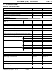
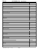
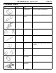
11A-1-1 6G7 ENGINE (E - W) - Specifications 1. SPECIFICATIONS SERVICE SPECIFICATIONS Items Standard Limit Auto-tensioner rod length mm 3.8 - 5.0 - Auto-tensioner rod projection length mm 12 - Auto-tensioner rod pushed-in amount (when pushed with a force of 98 - 196 N) mm 1.0 or less - Intake 37.71 37.21 Exhaust 37.14 36.64 Camshaft journal outside diameter mm 45 - Lash adjuster leak down time [diesel fuel at 15 - 20_C] seconds/mm 4 - 20/1.
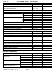
11A-1-2 6G7 ENGINE (E - W) - Specifications Items Standard Limit Oil pump side clearance mm 0.04 - 0.10 - Oil pump body clearance mm 0.10 - 0.18 0.35 91.1 - No. 1 0.03 - 0.07 0.1 No. 2 0.02 - 0.06 0.1 No. 1 0.30 - 0.45 0.8 No. 2 0.45 - 0.60 0.8 Oil ring side rail 0.20 - 0.60 1.0 Piston pin outside diameter mm 22.0 - Piston pin press-in load N (Room temperature) 7,350 - 17,200 - Crankshaft pin oil clearance mm 0.02 - 0.05 0.1 Connecting rod big end side clearance mm 0.
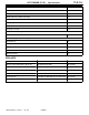
11A-1-3 6G7 ENGINE (E - W) - Specifications TORQUE SPECIFICATIONS Items Nm Alternator Drive belt tensioner pulley nut 49 Crankshaft bolt 181 Alternator pivot nut 44 Alternator bolt M8 21 Alternator bolt M10 48 Dipstick tube 13 Air intake plenum Air intake plenum stay bolt M8 17 Air intake plenum stay bolt M10 35 Accelerator cable bracket 4 Bracket 11 Throttle body bolt 11 Air intake plenum bolt and nut 17 Exhaust gas recirculation valve bolt 21 Exhaust gas recirculation pipe bol
11A-1-4 6G7 ENGINE (E - W) - Specifications Items Nm Intake manifold Engine coolant temperature gauge unit 11 Engine coolant temperature sensor 29 Heater pipe bolt 18 Water outlet fitting bolt 18 Water inlet fitting bolt 18 Thermostat housing bolt 18 Water pipe bolt 13 Delivery pipe 11 Intake manifold bolt 21 Fuel pipe bolt 8.8 Fuel pressure regulator bolt 8.
11A-1-5 6G7 ENGINE (E - W) - Specifications Items Nm Oil pan, upper bolt 5.9 Baffle plate bolt (oil pan side) 11 Baffle plate bolt (cylinder block side) 9.8 Oil screen bolt 18 Relief plug 44 Oil pump case bolt 13 Oil pump cover bolt 9.
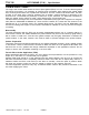
11A-1-6 6G7 ENGINE (E - W) - Specifications FORM-IN-PLACE GASKET The engine has several areas where the form-in-place gasket (FIPG) is in use. To ensure that the gasket fully serves its purpose, it is necessary to observe some precautions when applying the gasket. Bead size, continuity and location are of paramount importance. Too thin a bead could cause leaks. Too thick a bead, on the other hand, could be squeezed out of location, causing blocking or narrowing of the fluid feed line.
6G7 ENGINE (E - W) - Special Tools 11A-2-1 2.
A-2-2 Tool E Mitsubishi Motors Corporation 6G7 ENGINE (E - W) - Special Tools Number Name Use MD998774 Valve stem seal installer Installation of valve stem seal MD998780 Piston pin setting tool Removal and installation of piston pin MD998781 Flywheel stopper Holding flywheel or drive plate MD998767 Tensioner pulley Adjustment of timing belt tension MB990767 End yoke holder Holding camshaft sprocket (Used in combination with MD998715) MD998715 Pulley holder pin Holding camshaft sprock
11A-3-1 6G7 ENGINE (E - W) - Alternator 3. ALTERNATOR REMOVAL AND INSTALLATION 7 8 9 181 Nm 13 Nm 10 21 Nm 2 44 Nm 3 4 49 Nm 6 1 5 Removal steps 1. Tensioner pulley AA" "AA 2. Crankshaft bolt 3. Washer 4. Crankshaft pulley 5. Alternator E Mitsubishi Motors Corporation Dec. 1996 48 Nm 7EN1030 6. 7. 8. 9. 10.
11A-3-2 6G7 ENGINE (E - W) - Alternator REMOVAL SERVICE POINTS MD998781 AA" CRANKSHAFT BOLT (1) With the Special Tool fixed to the drive plate or flywheel remove the crankshaft bolt. 7EN0856 INSTALLATION SERVICE POINTS "AA CRANKSHAFT BOLT (1) With the Special Tool fixed to the drive plate or flywheel install the crankshaft bolt. E Mitsubishi Motors Corporation Dec.
11A-4-1 6G7 ENGINE (E - W) - Air Intake Plenum 4. AIR INTAKE PLENUM REMOVAL AND INSTALLATION 11 Nm 9 10 11 17 Nm 4 Nm 2 17 Nm 17 Nm 3 21 Nm 4 1 5 12 35 Nm 11 Nm 13 7 6 17 Nm 8 56 Nm 7EN1031 Removal steps 1. Air intake plenum stay, front 2. Air intake plenum stay, rear 3. Accelerator cable bracket 4. EGR valve 5. EGR valve gasket 6. EGR pipe 7. EGR pipe gasket E Mitsubishi Motors Corporation Dec. 1996 8. 9. 10. "AA 11. 12. 13.
11A-4-2 6G7 ENGINE (E - W) - Air Intake Plenum INSTALLATION SERVICE POINTS Protrusion "AA THROTTLE BODY GASKET (1) Install gasket with protrusion as illustrated. 6AE0277 E Mitsubishi Motors Corporation Dec.
6G7 ENGINE (E - W) - Ignition System 11A-5-1 5. IGNITION SYSTEM REMOVAL AND INSTALLATION 23 Nm 1 3 4 25 Nm 1 2 7EN0965 Removal steps 1. Spark plug cable 2. Spark plug 3. Distributor 4. O-ring E Mitsubishi Motors Corporation Dec.
11A-6-1 6G7 ENGINE (E - W) - Timing Belt 6. TIMING BELT REMOVAL AND INSTALLATION 23 Nm 21 22 20 13 Nm 19 88 Nm 7 6 23 Nm 10 9 14 12 44 Nm 17 18 8 48 Nm 44 Nm 16 11 13 1 15 2 11 Nm 5 13 Nm 9 Nm 11 Nm 3 7EN0862 44 Nm 4 Removal steps 1. Timing belt front upper cover, rear 2. Timing belt front upper cover, front 3. Timing belt front lower cover "DA 4. Engine support bracket 5. Crank angle sensor AA" "CA 6. Timing belt "BA 7. Automatic tensioner 8. Tensioner pulley 9. Tensioner arm 10.
11A-6-2 6G7 ENGINE (E - W) - Timing Belt REMOVAL SERVICE POINTS AA" TIMING BELT (1) When the timing belt is to be reused, in order to allow re-installation of the belt so that it travels in the same direction as before it was removed, mark the direction of travel with an arrow before removing it. Caution D As water or oil on the belt can seriously reduce its usable life, ensure that the timing belt, sprocket, and tensioner stay clean and dry while removed, and never wash them.
6G7 ENGINE (E - W) - Timing Belt 11A-6-3 (7) Badly worn teeth. Initial stage: Canvas is worn (fluffy canvas fibres are visible, rubber is gone and colour has changed to white. Canvas texture is not clear). Last stage: Canvas is worn out and rubber exposed and its width is reduced. (8) Missing tooth. Rubber exposed Tooth missing and canvas fiber exposed 8EN0068 AUTO-TENSIONER (1) Check for oil leaks. If oil leaks are evident, replace the auto-tensioner.
11A-6-4 6G7 ENGINE (E - W) - Timing Belt 2 A B 3 4 Slowly close the vice to force the rod in until the set hole (A) of the rod is lined up with the set hole (B) of the cylinder. Insert a metal wire (1.4 mm in diameter) into the set holes. Remove the auto-tensioner from the vice. (2) Install the auto tensioner on the cylinder block through the oil pump case. 7EN0227 "CA TIMING BELT (1) Turn the crankshaft sprocket to position its timing mark 3 teeth away from the timing mark on the crankcase.
11A-6-5 6G7 ENGINE (E - W) - Timing Belt (8) Using the Special Tool, turn the crankshaft counterclockwise a quarter turn, then turn it clockwise and align the timing marks. Make sure that all timing marks are in alignment. MD998769 7EN0744 Right bank Left bank Timing mark Water pump pulley Camshaft sprocket Camshaft sprocket Tensioner pulley Idler pulley Auto-tensioner Crankshaft sprocket Timing mark 7EN0745 E Mitsubishi Motors Corporation Dec.
11A-6-6 6G7 ENGINE (E - W) - Timing Belt MB998767 7EN0746 (9) Set the Special Tool and a torque wrench on the tensioner pulley. (10)Torque the tensioner pulley to 4.4 Nm. (11)While holding the tensioner pulley, tighten its centre bolt to the specified torque. (12)Turn the crankshaft 2 turns clockwise and let it stand for approx. 5 minutes. (13)Remove the wire, which was inserted when installing the tensioner, from the auto tensioner. If it can be removed easily, the timing belt tension is correct.
11A-7-1 6G7 ENGINE (E - W) - Intake Manifold 7. INTAKE MANIFOLD REMOVAL AND INSTALLATION 17 1 11 Nm 18 Nm 2 19 20 9 Nm 5 4 18 Nm 23 12 24 21 18 11 8 7 9 Nm 10 18 Nm 26 25 18 Nm 9 22 6 3 15 27 11 Nm 16 29 Nm 13 Nm 21 Nm 13 18 Nm 14 14 28 29 31 30 7EN0874 "HA "GA "FA "EA Removal steps 1. Engine harness 2. Injector and delivery pipe 3. Insulator 4. Fuel pressure regulator 5. O-ring 6. Insulator 7. Injector 8. O-ring 9. Grommet 10. Fuel pipe 11. O-ring 12. Delivery pipe 13.
11A-7-2 6G7 ENGINE (E - W) - Intake Manifold INSTALLATION SERVICE POINTS O-ring "AA O-RING / WATER PIPE (1) Wet the O-ring (with water) to facilitate assembly. Water pump Caution D Keep the O-ring of oil or grease. Water inlet pipe 6EN0594 "BA THERMOSTAT (1) Install the thermostat in the thermostat case with its jiggle valve located at the top position. Jiggle valve 7EN0876 "CA HEATER INLET AND OUTLET PIPES (1) Attach the outlet and inlet pipes in this order, one on the top of the other.
6G7 ENGINE (E - W) - Intake Manifold 11A-7-3 "FA INTAKE MANIFOLD (1) Tighten the nuts on the right bank to 5 - 8 Nm. (2) Tighten the nuts on the left bank to the specified torque. Then tighten the nuts on right bank to the specified torque. (3) Tighten the nuts on the left bank and those on the right bank again in that order. Front 7IN0090 "GA INJECTOR (1) Apply a small amount of engine oil to the O-ring. Caution D Take care to prevent the engine oil from entering the delivery pipe.
11A-8-1 6G7 ENGINE (E - W) - Exhaust Manifold & Water Pump 8. EXHAUST MANIFOLD & WATER PUMP REMOVAL AND INSTALLATION 13 Nm 1 2 3 5 13 Nm 35 Nm 4 49 Nm 7 9 41 Nm 6 23 Nm 8 49 Nm 7EN0966 Removal steps 1. Heat protector, rear 2. Exhaust manifold, rear "BA 3. Exhaust manifold gasket, rear 4. Heat protector, front 5. Engine lift bracket E Mitsubishi Motors Corporation Dec. 1996 6. Exhaust manifold, front "BA 7. Exhaust manifold gasket, front "AA 8. Water pump 9.
11A-8-2 6G7 ENGINE (E - W) - Exhaust Manifold & Water Pump INSTALLATION SERVICE POINTS O-ring "AA O-RING / WATER PIPE (1) Wet the O-ring (with water) to facilitate assembly. Water pump Caution D Keep the O-ring free of oil grease.
11A-9-1 6G7 ENGINE (E - W) - Rocker Arms and Camshaft 9. ROCKER ARMS AND CAMSHAFT REMOVAL AND INSTALLATION 1 3.4 Nm 31 Nm 6 2 10 9 8 3 9 5 8 8 9 13 7 7 11 12 7 12 Nm 12 12 14 15 16 17 Apply engine oil to all moving parts before installation. 4 7EN0879 Removal steps 1. Rocker cover 2. Gasket 3. Oil seal "EA 4. Oil seal AA" 5. Rocker arms, Rocker arm shaft AA" 6. Rocker arms, Rocker arm shaft "DA 7. Rocker shaft spring 8. Rocker arm “A” 9.
11A-9-2 6G7 ENGINE (E - W) - Rocker Arms and Camshaft REMOVAL SERVICE POINTS MD998443 AA" LASH ADJUSTER (1) Before removing the rocker arms and rocker arm shafts, install the Special Tools to prevent the lash adjusters from falling off. 6AE0160 INSPECTION CAMSHAFT (1) Measure the cam height. Standard value: IN: 37.71 mm EX: 37.14 mm 9EN0058 Limit: IN: 37.21 mm EX: 36.64 mm LASH ADJUSTER LEAK DOWN TEST Caution D The lash adjuster is a precision part. Keep it free from dust and other foreign matters.
6G7 ENGINE (E - W) - Rocker Arms and Camshaft 11A-9-3 INSTALLATION SERVICE POINTS "AA CAMSHAFT (1) Before attaching the camshafts, apply engine oil to the journals and cams. Take care not to confuse the right bank and left bank camshafts. Slot Right bank Approx 60_ 7EN0708 Left bank NOTE The right bank camshaft has 4-mm-wide slits in the rear end surface. (2) Make sure the camshaft dowel pin is at the location shown.
11A-9-4 6G7 ENGINE (E - W) - Rocker Arms and Camshaft "DA ROCKER SHAFT SPRING (1) Insert the rocker shaft spring at a slant with respect to the spark plug guide and install it normal to the guide. Rocker shaft spring 7EN0723 "EA OIL SEAL MD998713 6AE0164 Left bank side MD998713 E Mitsubishi Motors Corporation MB991559 7EN0724 Dec.
11A-10-1 6G7 ENGINE (E - W) - Cylinder Head and Valves 10. CYLINDER HEAD AND VALVES REMOVAL AND INSTALLATION 1 Apply engine oil to all moving parts before installation. 108 Nm 2 5 6 7 13 14 11 16 17 3 9 22 15 10 18 21 12 19 20 8 4 7EN0915 AA" AB" "CA "BA AB" "CA "BA Removal steps 1. Cylinder head bolt 2. Washer 3. Cylinder head assembly 4. Cylinder head gasket 5. Retainer lock 6. Valve spring retainer 7. Valve spring 8. Intake valve 9. Retainer lock 10. Valve spring retainer 11.
11A-10-2 6G7 ENGINE (E - W) - Cylinder Head and Valves REMOVAL SERVICE POINTS AA" CYLINDER HEAD BOLT MD998051 6AE0166 MD998735 AB" RETAINER LOCK (1) Attach a tag with the cylinder No. and mounting location to the detached valves, springs and other parts and store them for reassembly. 7EN0892 MD998772 6AE0167 AC" VALVE STEM SEAL Caution D Do not reuse the stem seal. 7EN0444 E Mitsubishi Motors Corporation Dec.
6G7 ENGINE (E - W) - Cylinder Head and Valves 11A-10-3 INSPECTION 7EN0258 CYLINDER HEAD (1) Check the cylinder head for water leaks, gas leaks, damage or cracks before washing it. (2) Completely remove oil, fur, sealer, carbon and the like. After washing the oil passages, blow air through them to make sure they are not clogged. (3) To ensure flatness of the cylinder head bottom surface, measure the distortion of the surface using a straight edge and a thickness gauge.
11A-10-4 6G7 ENGINE (E - W) - Cylinder Head and Valves VALVE GUIDE (1) Measure the clearance between the valve guide and the valve stem. When the clearance exceeds the specified limit, change the valve guide or the valve or both. Stem outside diameter Guide inside diameter Standard value: Intake 0.02 - 0.04 mm Exhaust 0.04 - 0.06 mm Limit: Intake 0.10 mm Exhaust 0.
6G7 ENGINE (E - W) - Cylinder Head and Valves 11A-10-5 VALVE GUIDE REPLACEMENT PROCEDURE (1) Remove the snap ring from the exhaust valve guide. (2) Pull out to the cylinder block side using a press. (3) Machine the valve guide hole in the cylinder head to match the oversize valve guide to be press fitted. Caution D Do not press fit another valve guide of the same size. 14.0 mm 7EN0726 Diameter of the 0.05 O.S. 0.25 O.S. 0.50 O.S. valve 11.05 11.25 11.50 guide hole - 11.07 mm - 11.27 mm - 11.
11A-10-6 Identification colour 6G7 ENGINE (E - W) - Cylinder Head and Valves Spring retainer "BA VALVE SPRING (1) Install the valve spring painted red side up. Stem seal Spring seal 6EN0544 MD998735 "CA VALVE RETAINER LOCK (1) Using Special Tool install the valve retainer lock. 7EN0892 MD998772 6AE0167 E Mitsubishi Motors Corporation Dec.
11A-11-1 6G7 ENGINE (E - W) - Oil Pan and Oil Pump 11. OIL PAN AND OIL PUMP REMOVAL AND INSTALLATION Apply engine oil to all moving parts before installation. 20 21 22 18 13 13 Nm 9.8 Nm 9.8 Nm 19 3 18 Nm 16 15 17 41 Nm 12 14 4 11 44 Nm 11 Nm 1 9.8 Nm 10 9.8 Nm 23 Nm 9 23 Nm 8 11 Nm 7 2 39 Nm 5 5.9 Nm 6 11 Nm 7EN0893 "GA "FA AA" "EA AB" "DA Removal steps 1. Oil pressure switch 2. Oil filter 3. Oil filter bracket 4. Oil filter bracket gasket 5. Drain plug 6. Drain plug gasket 7.
11A-11-2 6G7 ENGINE (E - W) - Oil Pan and Oil Pump REMOVAL SERVICE POINTS AA" OIL PAN (LOWER) (1) Apply wood to the oil pan side and remove the oil pan lower with a plastic hammer. AB" OIL PAN (UPPER) (1) Detach the bolt (1) shown at left. (2) Detach all other bolts. 1 7EN0564 (3) Screw a bolt into bolt hole A shown (at both ends) to remove the oil pan. Caution D Do not use a scraper or special tool to remove the oil pan.
6G7 ENGINE (E - W) - Oil Pan and Oil Pump 11A-11-3 (2) Check for side clearance. Standard value: 0.04 - 0.10 mm 7EN0511 (3) Check for body clearance. Standard value: 0.10 - 0.18 mm Limit: 0.35 mm 7EN0512 INSTALLATION SERVICE POINTS Alignment marks "AA OIL PUMP INNER AND OUTER ROTORS (1) Install the oil pump outer rotor in the proper direction using the setting mark drawn on it before disassembly. Apply engine oil over the entire rotor surface.
11A-11-4 6G7 ENGINE (E - W) - Oil Pan and Oil Pump "CA OIL SEAL Oil pump case MD998717 MD998717 7EN0139 Crankshaft Guide Oil seal 7EN0468 "DA OIL PAN (UPPER) (1) Clean the gasket coating surfaces of the cylinder block and the oil pan upper. (2) Squeeze out a 4 mm bead of liquid gasket and coat the coating surface with it. A Top view Flange bolt tightening sequence 18 17 14 8 4 1 13 7 3 2 Bottom view 9 Liquid gasket: MITSUBISHI GENUINE Part No.
6G7 ENGINE (E - W) - Oil Pan and Oil Pump 11A-11-5 "EA OIL PAN (LOWER) (1) Clean the gasket coating surfaces of the oil pan upper and the oil pan lower. (2) Squeeze out a 4 mm bead of liquid gasket and coat the coating surface with it. Liquid gasket: MITSUBISHI GENUINE Part No.
11A-12-1 6G7 ENGINE (E - W) - Piston and Connecting Rod 12. PISTON AND CONNECTING ROD REMOVAL AND INSTALLATION Apply engine oil to all moving parts before installation. 8 6 10 4 7 9 11 12 5 3 2 1 51 Nm 7EN0424 Removal steps 1. Connecting rod cap nut AA" "EA 2. Connecting rod cap 3. Connecting rod bearing, lower "DA 4. Piston and connecting rod assembly 5. Connecting rod bearing, upper "CA 6. Piston ring No. 1 E Mitsubishi Motors Corporation Dec. 1996 "CA 7. Piston ring No. 2 "BA 8.
11A-12-2 6G7 ENGINE (E - W) - Piston and Connecting Rod REMOVAL SERVICE POINTS Cylinder No. AA" CONNECTING ROD CAP (1) Enter the cylinder No. on the side of the large end of the connecting rod to facilitate reassembly. 7EN0448 Push rod Guide B Guide A: 17.9 mm AB" PISTON PIN The special piston pin setting tool (MD998780) consists of the parts shown at left. Guide A: 18.9 mm Guide C Guide A: 20.9 mm Base Guide A: 21.
6G7 ENGINE (E - W) - Piston and Connecting Rod 11A-12-3 INSPECTION PISTON RING (1) Check the clearance between the piston ring and the ring groove. If it exceeds the specified limit, change the ring or the piston and piston ring. Standard values: No. 1 0.03 - 0.07 mm No. 2 0.02 - 0.06 mm Limit: 0.1 mm 7EN0475 (2) Place the piston ring in the cylinder bore, push it in by applying the piston head side, and make sure it is square. Then measure the clearance at the ring ends with a thickness gauge.
11A-12-4 6G7 ENGINE (E - W) - Piston and Connecting Rod INSTALLATION SERVICE POINTS C D Connecting rod Piston pin Piston "AA PISTON PIN (1) Measure the dimensions of the following parts and portions: A: Piston pin mounting portion B: Distance between piston bosses C: Piston pin D: Connecting rod (2) Calculate by substituting each measured value into the following equation: L = A B 7EN0432 3 mm + L Guide B (A - C) - (B - D) 2 (3) Insert the special push rod tool into the piston pin and attach gu
11A-12-5 6G7 ENGINE (E - W) - Piston and Connecting Rod "BA OIL RING (1) Install the oil ring spacer into the piston ring groove. Next install the upper side rail into the piston ring groove, and then install the lower side rail. NOTE D There is no distinction between the upper and lower surfaces of the side rail and spacer. D The spacer and side rail (new part) are painted the following colour to enable size identification. Side rail end Side rail Identification colour S.T.D. None 0.50 mm O.S.
11A-12-6 6G7 ENGINE (E - W) - Piston and Connecting Rod No. 1 Upper side rail Piston pin No. 2 ring gap and spacer gap Lower side rail 6EN0549 "DA PISTON AND CONNECTING ROD (1) Liberally coat the circumference of the piston, piston ring, and oil ring with engine oil. (2) Arrange the piston ring and oil ring gaps (side rail and spacer) as shown in the figure. (3) Rotate the crankshaft so that the crank pin is positioned at the centre line of the cylinder bore.
6G7 ENGINE (E - W) - Crankshaft, Flywheel and Drive Plate 11A-13-1 13. CRANKSHAFT, FLYWHEEL AND DRIVE PLATE REMOVAL AND INSTALLATION 1 2 Apply engine oil to all moving parts before installation. 6 8 74 Nm 11 Nm 11 Nm 7 5 4 3 74 Nm 18 16 15 17 14 12 11 13 10 9 93 Nm 7EN1032 Removal steps 1. Adaptor plate 2. Drive plate 3. Plate 4. Adaptor plate 5. Flywheel 6. Rear plate "DA 7. Oil seal case "CA 8. Oil seal "BA 9. Bearing cap bolt E Mitsubishi Motors Corporation Dec.
11A-13-2 6G7 ENGINE (E - W) - Crankshaft, Flywheel and Drive Plate INSPECTION Plastigauge CRANKSHAFT OIL CLEARANCE (PLASTIGAUGE METHOD) NOTE If the oil clearance exceeds the limit, replace the bearing, and crankshaft if necessary. This crankshaft oil clearance can be measured easily by using a plastic gauge, as follows: 7EN0459 1 2 3 4 5 6 7EN0141 Remove oil and grease and any other foreign material from crankshaft journal and bearing inner surface. Install the crankshaft.
6G7 ENGINE (E - W) - Crankshaft, Flywheel and Drive Plate 11A-13-3 BORING CYLINDER (1) Oversize pistons to be used should be determined on the basis of the largest bore cylinder. Piston size identification Piston O.D. Thrust direction 6EN0554 Size Identification mark 0.50 mm O.S. 0.50 1.00 mm O.S. 1.00 NOTE Size mark is stamped on the piston top. (2) Measure outside diameter of piston to be used. Measure it in thrust direction as shown. (3) Based on the measured piston O.D.
11A-13-4 6G7 ENGINE (E - W) - INSTALLATION SERVICE POINTS Identification colour position "AA CRANKSHAFT BEARING When bearing replacement is required, select and install the correct bearing by the following procedure. (1) Measure the crankshaft journal diameter and confirm its classification from the following table. In the case of a crankshaft supplied as a service part, identification colours/marks of its journals are painted/stamped at the positions shown in the illustration. No. 4 journal No.
6G7 ENGINE (E - W) - Crankshaft, Flywheel and Drive Plate (3) Select the correct bearing from the above table on the basis of the identification data confirmed at steps 1 and 2. Identification mark Identification colour Oil groove 11A-13-5 Example D If the measured value of a crankshaft journal outer diameter is 59.996 mm, the journal is classified as “1” in the table.
11A-13-6 6G7 ENGINE (E - W) - Crankshaft, Flywheel and Drive Plate (4) Check the end play. If it exceeds the limit value, replace the thrust bearing. Standard value: 0.05 - 0.25 mm Limit: 0.3 mm 7EN0034 "CA CRANKSHAFT REAR OIL SEAL (1) Using the Special Tool, press-fit a new crankshaft rear oil seal into the seal case. MD998718 Oil seal case 7EN0465 "DA OIL SEAL CASE (1) Squeeze out a 3 mm bead of liquid gasket (FIPG) and apply it to the coating surface. Liquid gasket: MITSUBISHI GENUINE Part No.
NOTES