22B-0-1 MANUAL TRANSMISSION F5M41, F5M42, W5M42 CONTENTS GENERAL INFORMATION . . . . . . . . . . . . . . . . . . . . . . . . . . . . . . . . . . . . . . . . . . . 22B-0-3 1. SPECIFICATIONS . . . . . . . . . . . . . . . . . . . . . . . . . . . . . . . . . . . . . . . . . . . . . . . . . . 22B-1-1 TRANSMISSION MODEL TABLE . . . . . . . . . . . . . . . . . . . . . . . . . . . . . . . 22B-1-1 GEAR RATIO TABLE . . . . . . . . . . . . . . . . . . . . . . . . . . . . . . . . . . . . . . . . . .
2B-0-2 NOTES
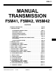
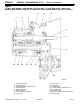
MANUAL TRANSMISSION (E - W) - General Information 22B-0-3 GENERAL INFORMATION F5M41 6 1 2 3 4 7 8 5 9 10 15 14 13 12 11 TFM0809 1. Reverse gear meshing noise prevention device 2. 5th-reverse speed synchronizer hub 3. 5th speed gear 4. 4th speed gear 5. 3rd-4th speed synchronizer hub 6. 3rd speed gear 7. Transmission case E Mitsubishi Motors Corporation July 1999 PWEE9508-F 8. 9. 10. 11. 12. 13. 14. 15.
22B-0-4 MANUAL TRANSMISSION (E - W) - General Information F5M41 6 1 3 2 4 7 8 5 9 10 15 14 13 12 11 1. Reverse gear meshing noise prevention device 2. 5th-reverse speed synchronizer hub 3. 5th speed gear 4. 4th speed gear 5. 3rd-4th speed synchronizer hub 6. 3rd speed gear 7. Transmission case E Mitsubishi Motors Corporation July 1999 PWEE9508-F 8. 9. 10. 11. 12. 13. 14. 15.
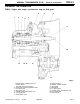
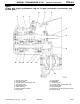
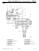
MANUAL TRANSMISSION (E - W) - General Information 22B-0-5 F5M42 4 2 1 5 6 3 7 8 9 16 15 14 13 12 11 10 1. 2. 3. 4. 5. 6. 7. 8. Reverse idler gear 4th speed gear 3rd-4th speed synchronizer hub 3rd speed gear Transmission case Clutch housing Release bearing retainer Input shaft E Mitsubishi Motors Corporation July 1999 9. 10. 11. 12. 13. 14. 15. 16.
22B-0-6 MANUAL TRANSMISSION (E - W) - General Information F5M42 4 1 5 6 3 2 7 8 9 16 15 14 13 12 11 10 1. 2. 3. 4. 5. 6. 7. 8. Reverse idler gear 4th speed gear 3rd-4th speed synchronizer hub 3rd speed gear Transmission case Clutch housing Release bearing retainer Input shaft E Mitsubishi Motors Corporation July 1999 9. 10. 11. 12.
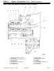
22B-0-7 MANUAL TRANSMISSION (E - W) - General Information W5M42 1 2 4 3 5 6 7 8 9 10 19 18 17 16 15 14 13 11 12 1. 2. 3. 4. 5. 6. 7. 8. 9. 10. Reverse idler gear 4th speed gear 3rd-4th speed synchronizer hub 3rd speed gear Transmission case Clutch housing Release bearing retainer Input shaft Output shaft Viscous coupling E Mitsubishi Motors Corporation Jun. 1998 11. 12. 13. 14. 15. 16. 17. 18. 19.
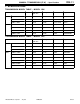
MANUAL TRANSMISSION (E - W) - Specifications 22B-1-1 1. SPECIFICATIONS TRANSMISSION MODEL TABLE - MODEL 1996 Transmission model Gear ratio Speedometer gear ratio Final gear ratio Vehicle model Engine model EUR F5M41-1-B8A1 B 31/36 3.454 CJ4A 4G92-MVV F5M41-1-F8A1 A 31/36 3.714 CJ4A, CK4A 4G92-MPI F5M41-1-R8A A 31/36 4.052 CJ1A, CK1A 4G13 F5M41-1-F8A1 A 31/36 3.714 CJ4A, CK4A 4G92-MPI F5M41-1-R8A A 31/36 4.052 CJ1A, CK1A 4G13 F5M41-1-R8A A 31/36 4.
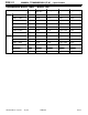
22B-1-2 MANUAL TRANSMISSION (E - W) - Specifications TRANSMISSION MODEL TABLE - MODEL 1998 Transmission model Gear ratio Speedometer gear ratio Final gear ratio Vehicle model Engine model EUR F5M41-1-B8A2 B 31/36 3.454 CJ4A 4G92 F5M41-1-F8A5 A 31/36 3.714 CJ4A 4G92 F5M41-1-R8A1 A 31/36 4.052 CK1A, CJ1A 4G13 F5M42-1-F71 D 30/36 3.722 EA2A, EA2W 4G63 F5M42-1-F8A4 D 31/36 3.722 DA2A 4G93-GDI F5M42-2-F6NA E 29/36 3.722 EA6A, EA6W 4D68 F5M42-2-F6N7 F 29/36 3.
MANUAL TRANSMISSION (E - W) - Specifications 22B-1-2a TRANSMISSION MODEL TABLE - MODEL 1999 Transmission model Gear ratio Speedometer gear ratio Final gear ratio Vehicle model Engine model EUR F5M42-1-V5A4 D 28/36 4.312 N61W 4G93-GDI F5M42-2-R5A3 G 28/36 4.058 N84W 4G64-GDI W5M42-1-V5A1 H 28/36 4.352 N94W 4G64-GDI F5M42-1-F8A G 31/36 3.722 DA2A 4G93-GDI F5M42-2-F7N2 D 30/36 3.722 EA2A, EA2W 4G93 F5M42-2-F6NC G 29/36 3.
22B-1-2b MANUAL TRANSMISSION (E - W) - Specifications TRANSMISSION MODEL TABLE - MODEL 2000 Transmission model Gear ratio Speedometer gear ratio Final gear ratio Vehicle model Engine model EUR F5M41-1-R8A1 A 31/36 4.052 CJ1A 4G13 F5M41-1-F8A5 A 31/36 3.714 CJ4A 4G92 F5M41-1-B8A2 B 31/36 3.454 CJ4A 4G92-MVV F5M42-1-R7A2 D 30/36 4.058 DA2A 4G93-GDI F5M42-1-V5A4 D 28/36 4.312 N61W 4G93-GDI F5M42-2-R5A3 G 28/36 4.058 N64W, N84W 4G64-GDI W5M42-1-V5A1 H 28/36 4.
MANUAL TRANSMISSION (E - W) - Specifications 22B-1-2c TRANSMISSION MODEL TABLE - MODEL 2001 Transmission model Gear ratio Speedometer gear ratio Final gear ratio Vehicle model Engine model EUR F5M41-1-R8A1 A 31/36 4.052 CJ1A 4G13 F5M41-1-F8A5 A 31/36 3.714 CJ4A 4G92 F5M41-1-F8AC B 31/36 3.454 DG5A 4G93 F5M42-2-R7A2 D 30/36 4.058 DA2A 4G93 F5M42-2-F7N2 D 30/36 3.722 EA2A, W 4G63 F5M42-2-F6NC G 29/36 3.722 EA3A, W 4G64 F5M42-2-F6N7 F 29/36 3.
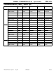
22B-1-2d MANUAL TRANSMISSION (E - W) - Specifications GEAR RATIO TABLE A B C D E F G 1st 3.583 3.727 3.071 3.583 3.583 3.583 3.583 2nd 1.947 1.947 1.947 1.947 1.947 1.947 1.947 3rd 1.343 1.343 1.379 1.379 1.379 1.379 1.266 4th 0.976 0.976 1.030 1.030 1.030 1.030 0.970 5th 0.804 0.804 0.820 0.820 0.733 0.767 0.767 Reverse 3.416 3.416 3.363 3.363 3.363 3.363 3.363 H 1st 3.583 2nd 1.947 3rd 1.266 4th 0.970 5th 0.767 Reverse 3.363 Transfer 0.
22B-1-2e MANUAL TRANSMISSION (E - W) - Specifications Items Allowable range Limit Front differential case preload mm 0.05 - 0.11 - Center differential case pinion backlash mm 0.025 - 0.150 - Center differential case preload mm 0.05 - 0.11 - Synchronizer ring back surface to gear clearance mm - 0.
MANUAL TRANSMISSION (E - W) - Specifications 22B-1-3 FORM-IN-PLACE GASKET The transmission has several areas where the form-in-place gasket (FIPG) is in use. To ensure that the gasket fully serves its purpose, it is necessary to observe some precautions when applying the gasket. Bead size, continuity and location are of paramount importance. Too thin a bead could cause leaks. Too thick a bead, on the other hand, could be squeezed out of location, causing blocking or narrowing of the fluid feed line.
22B-1-4 MANUAL TRANSMISSION (E - W) - Specifications SNAP RINGS, SPACERS AND THRUST PLATE ADJUSTMENT Part name Thickness mm Identification symbol Part No. Snap ring (For adjustment of input shaft front bearing end play) 2.24 None MD706537 2.31 Blue MD706538 2.38 Brown MD706539 2.31 Black (2) MD747149 2.35 None MD746561 2.39 Blue MD746562 2.43 Brown MD746563 2.47 Green MD746564 2.51 White MD746565 2.55 Yellow MD746566 2.59 Black MD746567 2.63 Orange MD746568 2.
22B-1-5 MANUAL TRANSMISSION (E - W) - Specifications Part name Thickness mm Identification symbol Part No. Snap ring: F5M41 (For adjustment of output shaft rear bearing end play) 2.31 Black (2) MD748800 2.35 None MD748801 2.39 Blue MD748802 2.43 Brown MD748803 2.47 Green MD748804 2.51 White MD748805 2.55 Yellow MD748806 2.59 Black MD748807 2.63 Orange MD748808 2.67 Blue MD748809 2.71 Brown MD748810 2.81 Green MD748782 2.85 White MD748783 2.
22B-1-6 MANUAL TRANSMISSION (E - W) - Specifications Part name Thickness mm Identification symbol Part No. Spacer: F5M41 (For adjustment of differential case end play) 0.77 77 MD754476 0.86 86 MD720938 0.95 95 MD720941 1.04 04 MD720944 1.13 D MD700270 1.22 G MD700271 1.31 E MD706574 1.40 None MD706573 1.49 C MD706572 1.58 B MD706571 1.67 A MD706570 1.
22B-1-7 MANUAL TRANSMISSION (E - W) - Specifications Part name Thickness mm Identification symbol Part No. Spacer: F5M42 (For adjustment of differential case preload) 0.71 71 MD754475 0.74 74 MD727660 0.77 77 MD754476 0.80 80 MD727661 0.83 83 MD720937 0.86 86 MD720938 0.89 89 MD720939 0.92 92 MD720940 0.95 95 MD720941 0.98 98 MD720942 1.01 01 MD720943 1.04 04 MD720944 1.07 07 MD720945 1.10 J MD710454 1.13 D MD700270 1.16 K MD710455 1.19 L MD710456 1.
22B-1-8 MANUAL TRANSMISSION (E - W) - Specifications Part name Thickness mm Identification symbol Part No. Spacer: W5M42 (For adjustment of center differential case preload) 0.74 74 MD727660 0.77 77 MD745476 0.80 80 MD727661 0.83 83 MD720937 0.86 86 MD720938 0.89 89 MD720939 0.92 92 MD720940 0.95 95 MD720941 0.98 98 MD720942 1.01 01 MD720943 1.04 04 MD720944 1.07 07 MD720945 1.10 J MD710454 1.13 D MD700270 1.16 K MD710455 1.19 L MD710456 1.
MANUAL TRANSMISSION (E - W) - Specifications 22B-1-9 TORQUE SPECIFICATIONS TRANSMISSION Items Nm Under cover mounting bolt 6.9 Interlock plate bolt 30 Clutch housing- transmission case mounting bolt 44 Clutch release bearing retainer mounting bolt 9.8 Control housing mounting bolt 18 Shift cable bracket mounting bolt 18 Speedometer gear mounting bolt 3.
MANUAL TRANSMISSION (E - W) - Special Tools 22B-2-1 2.
22B-2-2 MANUAL TRANSMISSION (E - W) - Special Tools Tool E Mitsubishi Motors Corporation Number Name Use MD998346 Bearing outer race remover Removal of roller bearing outer race MD998772 Valve spring compressor Removal of roller bearing outer race MD998801 Bearing remover Installation and removal of gears, bearings and sleeves MD998812 Installer cap Use with Installer and Installer adapter MD998813 Installer-100 Use with Installer cap and Installer adapter MD998814 Installer-200 Use
MANUAL TRANSMISSION (E - W) - Special Tools Tool E Mitsubishi Motors Corporation 22B-2-3 Number Name MD998819 Installer (40) adapter Installation of 5th-reverse speed synchronizer hub, differential case bearing, 4th speed gear and 5th speed gear sleeve MD998820 Installer (42) adapter Installation of 5th speed gear sleeve, 2nd speed gear sleeve MD998822 Installer (46) adapter Installation of 1st speed gear sleeve,1st-2nd speed synchronizer hub , 2nd speed gear sl
22B-2-4 MANUAL TRANSMISSION (E - W) - Special Tools TRANSFER Tool E Mitsubishi Motors Corporation Number Name Use MB990887 Arm bush remover and installer ring Installation of transfer oil seal MB990891 Arm bush remover and installer base Installation of transfer oil seal MB990933 Installer adapter Installation of transfer cover oil seal MD998304 Oil seal installer Installation of transfer extension housing oil seal MD998800 Oil seal installer Installation of transfer cover oil seal Jun
MANUAL TRANSMISSION (E - W) - Transmission 22B-3-1 3. TRANSMISSION DISASSEMBLY AND REASSEMBLY 18 Nm 32 Nm 3 5 2 9 11 7 10 12 8 4 3.9 Nm 6 69 Nm 69 Nm 1 1 TFM0718 Disassembly steps 1. Roll stopper bracket 2. Insulator washer 3. Shift cable bracket 4. Insulator washer "MA 5. Select lever "LA 6. Speedometer gear 7. Back-up lamp switch 8. Gasket 9. Restrict ball 10. Gasket 11. Poppet spring 12. Gasket E Mitsubishi Motors Corporation Nov.
22B-3-2 MANUAL TRANSMISSION (E - W) - Transmission Lubricate all internal parts with gear oil during reassembly. 15 30 Nm 18 Nm 16 13 14 19 44 Nm 25 20 28 18 17 26 48 Nm 27 18 Nm 24 21 23 22 TFM0719 "KA "JA AA" "IA AB" "HA Disassembly steps 13. Interlock plate bolt 14. Gasket 15. Control housing 16. Neutral return spring 17. Reverse idler gear shaft bolt 18. Gasket 19. Sealing cap 20. Transmission case E Mitsubishi Motors Corporation Nov. 1995 AC" "GA 21. 22. 23. 24. "FA 25. 26.
MANUAL TRANSMISSION (E - W) - Transmission 22B-3-3 Lubricate all internal parts with gear oil during reassembly. 30 32 29 41 31 45 33 35 40 36 34 39 46 38 37 42 18 Nm 44 43 TFM0720 AD" AD" AD" AD" Disassembly steps "DA 29. Spring pin 30. 1st-2nd speed shift rail 31. 1st-2nd speed shift fork "DA 32. Spring pin "DA 33. Spring pin "CA 34. 5th speed shift rail "CA 35. 5th speed shift fork "CA 36. Reverse shift lug "CA 37. Snap ring E Mitsubishi Motors Corporation Nov.
22B-3-4 MANUAL TRANSMISSION (E - W) - Transmission DISASSEMBLY SERVICE POINTS Sealing cap AA" SEALING CAP REMOVAL AB" TRANSMISSION CASE REMOVAL Expand the snap ring to remove it from the snap ring groove of the ball bearing. NOTE Expansion of the snap ring causes the snap ring groove to get out of position because of the output shaft’s own weight. Snap ring AC" REVERSE IDLER GEAR SHAFT REMOVAL Shift the 3rd-4th speed synchronizer sleeve toward the 4th speed side.
MANUAL TRANSMISSION (E - W) - Transmission 22B-3-5 AE" INPUT SHAFT / OUTPUT SHAFT REMOVAL Remove the input and output shafts together. Output shaft Input shaft ADJUSTMENT BEFORE REASSEMBLY Solders SPACER SELECTION FOR DIFFERENTIAL CASE END PLAY ADJUSTMENT (1) Put solders (about 10 mm long, 1.6 mm in diameter) in the illustrated positions of the transmission case and install the differential. (2) Install the clutch housing and tighten the bolts to the specified torque.
22B-3-6 MANUAL TRANSMISSION (E - W) - Transmission 3rd-4th speed shift fork 3rd-4th speed shift rail 5th speed shift fork 5th speed shift rail Reverse interlock rail Reverse shift lug "CA REVERSE INTERLOCK RAIL / STEEL BALL / 5TH SPEED SHIFT RAIL / REVERSE SHIFT LUG / SNAP RING / 5TH SPEED SHIFT FORK / 3RD-4TH SPEED SHIFT FORK / 3RD-4TH SPEED SHIFT RAIL INSTALLATION (1) Install the 3rd-4th shift rail and fork.
MANUAL TRANSMISSION (E - W) - Transmission 22B-3-7 "EA SPACER INSTALLATION Install the spacer selected in the section “ADJUSTMENT BEFORE REASSEMBLY”. "FA OIL GUIDE INSTALLATION Oil guide "GA REVERSE IDLER GEAR SHAFT INSTALLATION (1) Shift the 3rd-4th speed synchronizer sleeve toward the 4th speed side. 3rd-4th speed synchronizer sleeve (2) Face the threaded hole of the reverse idler gear shaft toward the direction shown.
22B-3-8 MANUAL TRANSMISSION (E - W) - Transmission (2) Install the transmission case and expand the snap ring. (3) Tighten the transmission case mounting bolts to the specified torque. NOTE Place the transmission upside down and let the snap ring fit in the groove by taking advantage of the output shaft’s own weight. Snap ring "IA SEALING CAP INSTALLATION Press-fit the sealing cap all the way up to the illustrated position.
MANUAL TRANSMISSION (E - W) - Transmission 22B-3-9 "LA SPEEDOMETER GEAR INSTALLATION Apply transmission oil to the O-ring of the speedometer gear. O-ring Transmission oil: Hypoid gear oil SAE 75W-85W conforming to API classification GL-4 or higher Control shaft Select lever shoe "MASELECT LEVER INSTALLATION Apply grease to the control shaft sliding portion of the select lever shoe. Specified grease: MITSUBISHI genuine grease part No.
MANUAL TRANSMISSION (E - W) - Transmission 22B-4-1 4. TRANSMISSION DISASSEMBLY AND REASSEMBLY Apply gear oil to all moving parts before installation. 18 Nm 32 Nm 5 4 7 8 3.9 Nm 9 10 69 Nm 32 Nm 6 15 14 3 13 2 3 11 19 Nm 12 1 69 Nm 69 Nm Disassembly steps 1. Transfer 2. O-ring 3. Roll stopper bracket 4. Shift cable bracket "KA 5. Select lever "JA 6. Speedometer gear 7. Back-up lamp switch 8. Gasket 9. Poppet spring 10. Gasket 11.
22B-4-2 MANUAL TRANSMISSION (E - W) - Apply gear oil to all moving parts before installation. Transmission 18 18 Nm 30 Nm 19 16 24 17 44 Nm 25 27 26 21 22 23 28 48 Nm 29 20 6.9 Nm TFM0597 "IA "HA AA" "GA AB" "FA "EA "DA Disassembly steps 16. Interlock plate bolt 17. Gasket 18. Control housing 19. Neutral return spring 20. Under cover 21. Reverse idler gear shaft bolt 22. Gasket 23. Reverse idler gear 24. Sealing cap 25. Transmission case 26. Outer race 27. Spacer 28.
MANUAL TRANSMISSION (E - W) - Transmission 22B-4-3 Apply gear oil to all moving parts before installation. 31 33 34 32 30 42 36 38 37 35 43 39 18 Nm 41 40 TFM0598 AC" AC" AC" AC" AD" AD" Disassembly steps "CA 30. Spring pin 31. 1st-2nd speed shift rail 32. 1st-2nd speed shift fork "CA 33. Spring pin "CA 34. Spring pin "BA 35. 3rd-4th speed shift rail "BA 36. 3rd-4th speed shift fork "BA 37. 5th-reverse speed shift rail "BA 38. 5th-reverse speed shift fork 39.
22B-4-4 MANUAL TRANSMISSION (E - W) - Transmission DISASSEMBLY SERVICE POINTS Sealing cap AA" SEALING CAP REMOVAL Drive a screwdriver into the sealing cap at the center, then pry off the sealing cap with the screwdriver. AB" TRANSMISSION CASE REMOVAL Expand the snap ring to remove it from the snap ring groove of the ball bearing. NOTE Expansion of the snap ring causes the snap ring groove to get out of position because of the output shaft’s own weight.
MANUAL TRANSMISSION (E - W) - Transmission 22B-4-5 ADJUSTMENT BEFORE REASSEMBLY Solders SPACER SELECTION FOR DIFFERENTIAL CASE PRELOAD ADJUSTMENT (1) Put solders (about 10 mm long, 1.6 mm in diameter) in the illustrated positions of the transmission case and install the bearing outer race and differential. (2) Install the clutch housing and tighten the bolts to the specified torque. (3) If the solders are not crushed, put larger diameter solders and repeat Steps (1) and (2).
22B-4-6 MANUAL TRANSMISSION (E - W) 5th-reverse speed shift rail Transmission (3) While fitting each shift fork in the sleeve, slide the shift rails in the direction shown and install. 3rd-4th speed shift rail Shift rail Shift fork 2.5 mm "CA SPRING PIN INSTALLATION Install the spring pin such that its slit may face in the axial direction of the shift rail. Spring pin Slit "DA SPACER INSTALLATION Install the spacer selected in the section “ADJUSTMENT BEFORE REASSEMBLY”.
MANUAL TRANSMISSION (E - W) - Transmission 22B-4-7 (2) Install the transmission case and expand the snap ring. (3) Tighten the transmission case to the specified torque. NOTE Place the transmission upside down and let the snap ring fit in the groove by taking advantage of the output shaft’s own weight. Snap ring "GA SEALING CAP INSTALLATION Press-fit the sealing cap all the way up to the illustrated position. Sealing cap MB990938 MB990927 "HA UNDER COVER INSTALLATION Apply a 1.
22B-4-8 MANUAL TRANSMISSION (E - W) - Transmission "JA SPEEDOMETER GEAR INSTALLATION Apply transmission oil to the O-ring of the speedometer gear. O-ring Transmission oil: Hypoid gear oil SAE 75W-85W conforming to API classification GL-4 or higher Control shaft Select lever shoe "KA SELECT LEVER INSTALLATION Apply grease to the control shaft sliding portion of the select lever shoe. Specified grease: MITSUBISHI genuine grease part No.
22B-5-1 MANUAL TRANSMISSION (E - W) - Input Shaft 5. INPUT SHAFT DISASSEMBLY AND REASSEMBLY Apply gear oil to all moving parts before installation. 15 17 19 20 23 22 24 16 25 18 2 21 27 6 28 5 1 4 7 29 3 13 25 26 14 8 9 11 10 12 13 TFM0834 Disassembly steps "MA 1. Snap ring AA" "LA 2. Ball bearing AB" "KA 3. Reverse brake sleeve 4. Needle roller bearing 5. Reverse brake cone 6. Reverse brake ring "DA 7. Synchronizer spring "JA 8.
22B-5-2 MANUAL TRANSMISSION (E - W) - Input Shaft DISASSEMBLY AND REASSEMBLY 14 15 Apply gear oil to all moving parts before installation. 16 17 19 18 20 21 2 23 24 5 9 25 7 1 21 22 11 3 10 12 4 13 6 8 9 Disassembly steps "MA 1. Snap ring AA" "LA 2. Ball bearing 3. Collar "JA 4. Synchronizer sleeve AC" "IA 5. 5th-reverse speed synchronizer hub 6. Synchronizer ring "DA 7. Synchronizer spring 8. 5th speed gear 9. Needle roller bearing AD" "HA 10.
MANUAL TRANSMISSION (E - W) - Input Shaft DISASSEMBLY SERVICE POINTS MD998801 AA" BALL BEARING REMOVAL AB" REVERSE BRAKE SLEEVE REMOVAL Mount a special tool on the 5th speed gear and remove the reverse brake sleeve. MD998801 AC" 5TH-REVERSE SPEED SYNCHRONIZER HUB REMOVAL Mount a special tool on the 5th speed gear and remove the 5th-reverse synchronizer hub. MD998917 AD" 5TH SPEED GEAR SLEEVE REMOVAL Mount a special tool on the 4th speed gear and remove the 5th speed gear sleeve.
22B-5-2b MANUAL TRANSMISSION (E - W) - Input Shaft Intentionally blank E Mitsubishi Motors Corporation July 1999 PWEE9508-F Added
MANUAL TRANSMISSION (E - W) - Input Shaft 22B-5-3 AF" BALL BEARING REMOVAL MD998801 REASSEMBLY SERVICE POINTS Oil seal "AA OIL SEAL INSTALLATION Drive in the oil seal all the way up to the illustrated dimension. 3.5 mm MD998812 MD998801 "BA BALL BEARING INSTALLATION MD998813 MD998817 "CA SNAP RING INSTALLATION Select and install a snap ring so that the input shaft front bearing end play will have the standard value. Standard value: - 0.01 - 0.
22B-5-4 MANUAL TRANSMISSION (E - W) - Input Shaft "EA 3RD-4TH SPEED SYNCHRONIZER HUB INSTALLATION Install the 3rd-4th speed synchronizer hub in such a way that it will be oriented in the direction shown. Rear of transmission Identification mark MD998812 Caution When the hub is installed, make sure that the synchronizer ring is not caught.
MANUAL TRANSMISSION (E - W) - Input Shaft MD998812 MD998801 22B-5-5 "HA 5TH SPEED GEAR SLEEVE INSTALLATION MD998813 MD998820 "IA 5TH-REVERSE SPEED SYNCHRONIZER HUB INSTALLATION Install the 5th-reverse speed synchronizer hub in such a way that it will be oriented in the direction shown. Rear of transmission Identification mark MD998812 MD998819 Caution When the 5th-reverse speed synchronizer hub is installed, make sure that the synchronizer ring is not caught.
22B-5-6 MANUAL TRANSMISSION (E - W) - Input Shaft "KA REVERSE BRAKE SLEEVE INSTALLATION MD998812 MD998818 MD998801 MD998812 "LA BALL BEARING INSTALLATION MD998818 MD998801 "MASNAP RING INSTALLATION Select and install a snap ring so that the input shaft rear bearing end play will have the standard value. Standard value: - 0.01 - 0.09 mm INSPECTION INPUT SHAFT (1) Check the outside diameter of the needle bearing mounting portion for damage, abnormal wear and seizure.
MANUAL TRANSMISSION (E - W) - Input Shaft 22B-5-7 SYNCHRONIZER RING (1) Check to ensure that the clutch gear tooth surfaces are not damaged and broken. (2) Check to ensure that the cone inside diameter is not damaged or worn and that the threads are not crushed. (3) Press the synchronizer ring against the gear and check clearance “A”. If “A” is less than the limit, replace. A Limit: 0.
MANUAL TRANSMISSION (E - W) - Input Shaft 22B-6-1 6. INPUT SHAFT DISASSEMBLY AND REASSEMBLY Apply gear oil to all moving parts before installation. 9 11 10 12 14 13 15 16 2 19 18 4 20 6 7 1 8 3 16 17 5 TFM0591 Disassembly steps 1. Snap ring 2. Ball bearing 3. Thrust plate stopper 4. Thrust plate 5. 5th speed gear 6. 4th speed gear 7. Needle roller bearing AC" "GA 8. 4th speed gear sleeve 9. Synchronizer ring "DA 10.
22B-6-2 MANUAL TRANSMISSION (E - W) - Input Shaft MD998801 DISASSEMBLY SERVICE POINTS MD998801 AB" 5TH SPEED GEAR REMOVAL Use the special tool to remove the 5th speed gear. AA" BALL BEARING REMOVAL Use the special tool to remove the ball bearing. AC" 4TH SPEED GEAR SLEEVE REMOVAL Mount a special tool on the 3rd gear and remove the 4th speed gear sleeve. MD998801 AD" BALL BEARING REMOVAL Use the special tool to remove the ball bearing. MD998801 REASSEMBLY SERVICE POINTS Oil seal 3.
MANUAL TRANSMISSION (E - W) - Input Shaft MD998812 22B-6-3 "BA BALL BEARING INSTALLATION Use the special tools to install the ball bearing. MD998813 MD998801 MD998816 "CA SNAP RING INSTALLATION Select and install a snap ring so that the input shaft front bearing end play will have the standard value. Standard value: - 0.01 - 0.12 mm Snap ring "DA SYNCHRONIZER SPRING INSTALLATION Install the synchronizer spring securely up to the illustrated position of the synchronizer ring.
22B-6-4 MANUAL TRANSMISSION (E - W) - Input Shaft "FA SYNCHRONIZER SLEEVE INSTALLATION (1) Install the synchronizer sleeve in such a way that it will be oriented in the direction shown. Identification groove Rear of transmission Synchronizer sleeve (2) When the synchronizer sleeve is installed, make sure that the deep groove portion of the synchronizer hub is aligned with the projecting portion of the sleeve.
MANUAL TRANSMISSION (E - W) - Input Shaft Thrust plate stopper 22B-6-5 "JA THRUST PLATE STOPPER INSTALLATION When the thrust plate is installed, make sure that it is not tilted. Thrust plate MD998812 MD998801 "KA BALL BEARING INSTALLATION Use the special tools to install the ball bearing. MD998818 "LA SNAP RING INSTALLATION Select and install a snap ring so that the input shaft rear bearing end play will have the standard value. Standard value: - 0.01 - 0.
22B-6-6 MANUAL TRANSMISSION (E - W) - Input Shaft SYNCHRONIZER RING (1) Check to ensure that the clutch gear tooth surfaces are not damaged and broken. (2) Check to ensure that the cone inside diameter is not damaged or worn and that the threads are not crushed. (3) Press the synchronizer ring against the gear and check clearance “A”. If “A” is less than the limit, replace. A Limit: 0.
22B-7-1 MANUAL TRANSMISSION (E - W) - Output Shaft 7. OUTPUT SHAFT DISASSEMBLY AND REASSEMBLY Apply gear oil to all moving parts before installation. 19 1 14 22 16 15 17 18 21 6 9 3 11 4 12 20 2 5 13 7 10 8 9 TFM0715 "JA AA" "IA "HA AB" "GA Disassembly steps 1. Snap ring 2. Ball bearing 3. Collar 4. 5th speed gear 5. 4th speed gear 6. Snap ring 7. 3rd speed gear 8. 2nd speed gear 9. Needle roller bearing 10.
22B-7-2 MANUAL TRANSMISSION (E - W) - Output Shaft DISASSEMBLY AND REASSEMBLY Apply gear oil to all moving parts before installation. 21 24 1 16 18 17 19 23 20 6 9 3 2 11 22 4 13 5 15 7 10 12 8 9 14 "JA AA" "IA "HA AB" "GA Disassembly steps 1. Snap ring 2. Ball bearing 3. Collar 4. 5th speed gear 5. 4th speed gear 6. Snap ring 7. 3rd speed gear 8. 2nd speed gear 9. Needle roller bearing 10. 2nd speed gear sleeve 11.
MANUAL TRANSMISSION (E - W) - Output Shaft 22B-7-2a DISASSEMBLY SERVICE POINTS AA" BALL BEARING REMOVAL MD998801 AB" 2ND SPEED GEAR SLEEVE REMOVAL Mount a special tool on the synchronizer sleeve and remove the 2nd speed gear sleeve.
22B-7-2b MANUAL TRANSMISSION (E - W) - Output Shaft Intentionally blank E Mitsubishi Motors Corporation July 1999 PWEE9508-F Added
MANUAL TRANSMISSION (E - W) - Output Shaft 22B-7-3 "BA SNAP RING INSTALLATION Select and install a snap ring so that the output shaft front bearing end play will have the standard value. Standard value: - 0.01 - 0.12 mm Snap ring "CA 1ST SPEED GEAR SLEEVE INSTALLATION MD998812 MD998814 Sleeve MD998822 "DA SYNCHRONIZER SPRING INSTALLATION Install the synchronizer spring securely up to the illustrated position of the synchronizer ring.
22B-7-4 MANUAL TRANSMISSION (E - W) - Output Shaft "FA SYNCHRONIZER SLEEVE INSTALLATION (1) Install the synchronizer sleeve in such a way that it will be oriented in the direction shown. Rear of transmission Synchronizer sleeve (2) When the synchronizer sleeve is installed, make sure that the deep groove portion of the synchronizer hub is aligned with the projecting portion of the sleeve.
MANUAL TRANSMISSION (E - W) - Output Shaft 22B-7-5 "JA SNAP RING INSTALLATION Select and install a snap ring so that the output shaft rear bearing end play will have the standard value. Standard value: - 0.01 - 0.09 mm "KA SYNCHRONIZER SPRING INSTALLATION Install the synchronizer spring securely in the illustrated position of the outer synchronizer ring. Synchronizer spring INSPECTION OUTPUT SHAFT Check the splines for damage and wear.
22B-7-6 MANUAL TRANSMISSION (E - W) - Output Shaft (3) Press the synchronizer ring against the gear and check clearance “A”. If “A” is less than the limit, replace. A Limit: 0.5 mm Synchronizer ring Gear OUTER SYNCHRONIZER RING / INNER SYNCHRONIZER RING / SYNCHRONIZER CONE (1) Check to ensure that the clutch gear tooth surfaces and cone surfaces are not damaged and broken. (2) Install the outer ring, inner ring and cone, press them against the gear, and check clearance “A”.
MANUAL TRANSMISSION (E - W) - Output Shaft 22B-7-7 SPEED GEARS (1) Check to ensure that the helical and clutch gear tooth surfaces are not damaged or worn. (2) Check to ensure that the synchronizer cone surfaces are not roughened, damaged or worn. (3) Check to ensure that the gear inside diameter and front and rear surfaces are not damaged and worn. E Mitsubishi Motors Corporation Nov.
MANUAL TRANSMISSION (E - W) - Output Shaft 22B-8-1 8. OUTPUT SHAFT DISASSEMBLY AND REASSEMBLY 18 Apply gear oil to all moving parts before installation. 20 19 22 24 21 23 25 28 26 27 29 30 31 4 1 34 5 33 32 13 3 2 12 15 7 17 16 AC" AD" July 1999 11 9 10 13 Disassembly steps "PA 1. Snap ring "OA 2. Ball bearing "NA 3. Reverse gear bearing sleeve "NA 4.
22B-8-2 MANUAL TRANSMISSION (E - W) - Output Shaft DISASSEMBLY AND REASSEMBLY Apply gear oil to all moving parts before installation. 20 31 33 32 24 36 27 28 29 30 19 18 21 22 23 4 25 26 5 6 13 12 15 34 17 35 1 3 2 14 16 7 8 10 11 4 9 13 Disassembly steps 1. Snap ring 2. Ball bearing 3.
MANUAL TRANSMISSION (E - W) - Output Shaft 22B-8-3 MD998917 MD998801 Ball bearing Sleeve Synchronizer hub MD998801 3rd speed gear DISASSEMBLY SERVICE POINTS AA" BALL BEARING REMOVAL Use the special tool to remove the ball bearing. AB" REVERSE GEAR BEARING SLEEVE REMOVAL Mount a special tool on the reverse gear and remove the reverse gear bearing sleeve.
22B-8-4 MANUAL TRANSMISSION (E - W) - Output Shaft AF" 1ST SPEED GEAR SLEEVE REMOVAL Use the special tool to remove the 1st speed gear sleeve. MD998801 MD998917 Sleeve Inner race MD998812 MD998801 MD998818 AG" ROLLER BEARING INNER RACE REMOVAL Use the special tool to remove the roller bearing inner race. REASSEMBLY SERVICE POINTS "AA ROLLER BEARING INNER RACE INSTALLATION Use the special tools to install the roller bearing inner race.
MANUAL TRANSMISSION (E - W) - Output Shaft 22B-8-5 "DA SYNCHRONIZER SPRING INSTALLATION Install the synchronizer spring securely up to the illustrated position of the synchronizer ring. Synchronizer spring "EA 1ST-2ND SPEED SYNCHRONIZER HUB INSTALLATION Install the 1st-2nd speed synchronizer hub in such a way that it will be oriented in the direction shown.
22B-8-6 MANUAL TRANSMISSION (E - W) - Output Shaft "GA SYNCHRONIZER SPRING INSTALLATION Install the synchronizer spring securely up to the illustrated position of the synchronizer ring. Synchronizer spring MD998812 "HA 2ND SPEED GEAR SLEEVE INSTALLATION Use the special tools to install the 2nd speed gear sleeve. MD998814 Sleeve MD998822 MD998812 "IA 3RD SPEED GEAR INSTALLATION Use the special tools to install the 3rd speed gear.
MANUAL TRANSMISSION (E - W) - Output Shaft 22B-8-7 MD998812 "LA 5TH SPEED GEAR SLEEVE INSTALLATION Use the special tools to install the 5th speed gear sleeve. MD998813 MD998819 Sleeve "MA5TH-REVERSE SPEED SYNCHRONIZER HUB INSTALLATION Install the 5th-reverse speed synchronizer hub in such a way that it will be oriented in the direction shown.
22B-8-8 MANUAL TRANSMISSION (E - W) - Output Shaft "PA SNAP RING INSTALLATION Select and install a snap ring so that the output shaft rear bearing end play will have the standard value. Standard value: - 0.01 - 0.09 mm Snap ring INSPECTION OUTPUT SHAFT Check the splines for damage and wear. NEEDLE ROLLER BEARING (1) Check to ensure that when the bearing sleeve and gear are combined and made to rotate, they rotate smoothly without looseness and noise.
MANUAL TRANSMISSION (E - W) - Output Shaft 22B-8-9 OUTER SYNCHRONIZER RING / INNER SYNCHRONIZER RING / SYNCHRONIZER CONE (1) Check to ensure that the clutch gear tooth surfaces and cone surfaces are not damaged and broken. F5M42-2-R5A3 only Gear (2) Install the outer ring, inner ring and cone, press them against the gear, and check clearance “A”. If “A” is less than the limit, replace. A Outer ring Cone Inner ring Gear Limit: 0.
22B-8-10 MANUAL TRANSMISSION (E - W) - Output Shaft SPEED GEARS (1) Check to ensure that the helical and clutch gear tooth surfaces are not damaged or worn. (2) Check to ensure that the synchronizer cone surfaces are not roughened, damaged or worn. (3) Check to ensure that the gear inside diameter and front and rear surfaces are not damaged and worn. E Mitsubishi Motors Corporation Jun.
MANUAL TRANSMISSION (E - W) - Reverse Idler Gear 22B-9-1 9. REVERSE IDLER GEAR DISASSEMBLY AND REASSEMBLY Apply gear oil to all moving parts before installation. 1 5 2 3 4 TFM0590 Disassembly steps 1. Snap ring 2. Thrust washer 3. Reverse idler gear 4. Needle roller bearing 5. Reverse idler gear shaft INSPECTION NEEDLE ROLLER BEARING (1) Check to ensure that when the shaft and gear are combined and made to rotate, they rotate smoothly without looseness and noise.
MANUAL TRANSMISSION (E - W) - Speedometer Gear 22B-10-1 10. SPEEDOMETER GEAR DISASSEMBLY AND REASSEMBLY Lubricate all internal parts with gear oil during reassembly. 4 2 3 1 TFM0593 Disassembly steps 1. e-clip 2. Speedometer driven gear 3. O-ring 4. Sleeve E Mitsubishi Motors Corporation Nov.
22B-11-1 MANUAL TRANSMISSION (E - W) - Select Lever 11. SELECT LEVER DISASSEMBLY AND REASSEMBLY 6 5 7 1 11 Nm 8 2 9 3 4 10 TFM0589 Disassembly steps "AA 1. Dust cover 2. Nut 3. Spring washer 4. Washer 5. Select lever bushing Select lever shoe Select lever Select lever bushing Dust cover Select lever shaft REASSEMBLY SERVICE POINT Dust cover E Mitsubishi Motors Corporation 6. 7. 8. "AA 9. 10. "AA DUST COVER INSTALLATION Nov.
22B-12-1 MANUAL TRANSMISSION (E - W) - Control Housing 12. CONTROL HOUSING DISASSEMBLY AND REASSEMBLY 13 7 12 8 1 9 15 4 5 6 16 2 3 17 14 20 11 10 19 18 22 Nm TFM0916 Disassembly steps AA" "FA 1. Lock pin 2. Interlock plate 3. Control finger 4. Pin 5. Return spring 6. Stopper plate "EA 7. Spring pin "DA 8. Spring pin 9. Stopper body 10. Neutral return spring 11. Spacer E Mitsubishi Motors Corporation Nov. 1995 Jun. 1998 12.
22B-12-2 MANUAL TRANSMISSION (E - W) - Control Housing DISASSEMBLY SERVICE POINT Lock pin AA" LOCK PIN REMOVAL Drive the lock pin out of position from the direction shown. Control finger REASSEMBLY SERVICE POINTS Control housing Model number stamped side Needle bearing "AA NEEDLE BEARING INSTALLATION Press fit the needle bearing up the illustrated dimension, while making sure that the model number stamped side is oriented in the direction shown.
MANUAL TRANSMISSION (E - W) - Control Housing Control shaft 22B-12-1 22B-12-2a "DA SPRING PIN INSTALLATION Stopper body Installation direction Slit Spring pin TFM0860 Spring pin "EA SPRING PIN INSTALLATION 45° TFM0861 "FA LOCK PIN INSTALLATION Drive in the lock pin in the direction shown in the illustration. Lock pin Control finger E Mitsubishi Motors Corporation Nov. 1995 Jan.
22B-13-1 MANUAL TRANSMISSION (E - W) - Clutch Housing 13. CLUTCH HOUSING DISASSEMBLY AND REASSEMBLY 4 7* 8 5 3 6 2 1 9.8 Nm TFM0759 Disassembly steps 1. Clutch release bearing retainer "EA 2. Oil seal "DA 3. Oil seal AA" "CA 4. Outer race AB" "BA 5. 6. "AA 7. 8. Outer race Oil guide Bushing* Clutch housing NOTE: Referring to INSTALLATION SERVICE POINTS is required only when the clutch housing is replaced.
22B-13-2 MANUAL TRANSMISSION (E - W) - Clutch Housing MD998772 MD998346 AB" OUTER RACE REMOVAL Use the special tools to remove the outer race. REASSEMBLY SERVICE POINTS Split ends Air purge groove "AA BUSHING INSTALLATION Press fit the bushing up to the illustrated position, while making sure that the split ends of the bushing do not coincide with the air purge groove.
MANUAL TRANSMISSION (E - W) - Clutch Housing MB990938 22B-13-3 "CA OUTER RACE INSTALLATION MB990935 "DA OIL SEAL INSTALLATION Apply transmission oil to the oil seal lip area. Specified oil: Hypoid gear oil SAE 75W-85W conforming to API classification GL-4 or higher MD998325 "EA OIL SEAL INSTALLATION Pack grease in the oil seal lip area. Specified grease: MITSUBISHI genuine grease part No. 0101011 or equivalent MB990938 MB990926 E Mitsubishi Motors Corporation Nov.
MANUAL TRANSMISSION (E - W) - Transmission Case 22B-14-1 14. TRANSMISSION CASE DISASSEMBLY AND REASSEMBLY 1 2 5 4 6 3 TFM0600 Disassembly steps "CA 1. Oil seal "BA 2. Needle bearing 3. Oil guide 4. Snap ring "AA 5. Bushing 6. Transmission case REASSEMBLY SERVICE POINTS "AA BUSHING INSTALLATION Press fit the bushing up to the illustrated position, while making sure that the split ends of the bushing do not coincide with the air purge groove.
22B-14-2 MANUAL TRANSMISSION (E - W) - Transmission Case 1 mm Model number stamped side "BA NEEDLE BEARING INSTALLATION Press fit the needle bearing until it is flush with the case, while making sure that the model number stamped side is oriented in the direction shown. "CA OIL SEAL INSTALLATION Apply transmission oil to the oil seal lip area. Specified oil: Hypoid gear oil SAE 75W-85W conforming to API classification GL-4 or higher MD998325 E Mitsubishi Motors Corporation Nov.
Differential , Front Differential MANUAL TRANSMISSION (E - W) - 22B-15-1 15. DIFFERENTIAL , FRONT DIFFERENTIAL DISASSEMBLY AND REASSEMBLY Apply gear oil to all moving parts before installation. 3 1 7 4 2 6 5 8 3 132 Nm 9 6 9 7 10 2 TFM0760 "EA AA" "DA AB" "CA "BA "AA "AA "AA "AA "AA Disassembly steps 1. Differential drive gear 2. Ball bearing 3. Taper roller bearing 4. Lock pin 5. Pinion shaft 6. Pinion 7. Washer 8.
22B-15-2 MANUAL TRANSMISSION (E - W) - Differential , Front Differential DISASSEMBLY SERVICE POINTS MD998801 AA" BALL BEARING REMOVAL Use the special tool to remove the ball bearing. AB" TAPER ROLLER BEARING REMOVAL Use the special tool to remove the taper roller bearing.
MANUAL TRANSMISSION (E - W) - Differential , Front Differential 22B-15-3 (4) Measure the backlash between the side gear and pinion. Standard value: 0.025 - 0.150 mm (5) If the backlash is out of specification, select a spacer and re-measure the backlash. NOTE Adjust until the backlashes on both sides are equal. "BA LOCK PIN INSTALLATION Install the lock pin in such a way that it will be oriented in the direction shown.
22B-15-4 MANUAL TRANSMISSION (E - W) - 3 (2) Tighten to the specified torque in the illustrated sequence. 1 5 Differential , Front Differential 8 7 6 2 4 E Mitsubishi Motors Corporation Jun.
22B-16-1 MANUAL TRANSMISSION (E - W) - Center Differential 16. CENTER DIFFERENTIAL DISASSEMBLY AND REASSEMBLY 1 Apply gear oil to all moving parts before installation. 3 2 5 6 12 7 11 132 Nm 12 4 17 14 10 9 12 13 8 12 11 9 16 15 "DA "CA AA" "BA "CA "CA "CA "CA "CA "CA Disassembly steps 1. Center differential drive gear 2. Center differential flange 3. Taper roller bearing 4. Snap ring 5. Front output shaft 6. Spacer 7. Side gear 8. Lock pin 9. Pinion shaft 10. 11. 12. 13.
22B-16-2 MANUAL TRANSMISSION (E - W) - Center Differential MD998917 MD990930 MB990937 MD998812 MD998823 AB" TAPER ROLLER BEARING REMOVAL Use the special tools to remove the taper roller bearing. REASSEMBLY SERVICE POINTS "AA TAPER ROLLER BEARING INSTALLATION Use the special tool to install the taper roller bearing. "BA TAPER ROLLER BEARING INSTALLATION Use the special tools to install the taper roller bearing.
MANUAL TRANSMISSION (E - W) - Center Differential 22B-16-3 (5) Install the front output shaft to the side gear and fit the snap ring. (6) Attach the spacer on the other side gear, then install the side gear in the center differential case. NOTE: If a new side gear is to be installed, select a spacer with medium thickness (0.93 - 1.00 mm). (7) Install the center differential flange on the case while aligning the mating marks, then secure it temporarily with machine screw.
22B-17-1 MANUAL TRANSMISSION (E - W) - Transfer 17. TRANSFER DISASSEMBLY AND REASSEMBLY 1 3 5 2 6 4 8 7 9 11 Apply gear oil to all moving parts before installation. 10 23 Nm "FA "EA "DA "AA "AA "CA "BA "AA Disassembly steps 1. Air breather 2. Dust seal guard 3. Oil seal 4. Oil seal 5. O-ring 6. O-ring 7. Oil seal 8. Oil seal 9. O-ring 10. Transfer cover 11. Transfer E Mitsubishi Motors Corporation Jun.
22B-17-2 MANUAL TRANSMISSION (E - W) - Transfer REASSEMBLY SERVICE POINTS "AA O-RING INSTALLATION Apply transmission oil to the O-ring. Transmission oil: Hypoid gear oil SAE 75W-85W conforming to API classification GL-4 or higher. "BA OIL SEAL INSTALLATION (1) Apply transmission oil to the oil seal lip area. MD998800 Transmission oil: Hypoid gear oil SAE 75W-85W conforming to API classification GL-4 or higher. (2) By using the special tool, install the oil seal.
MANUAL TRANSMISSION (E - W) - Transfer 22B-17-3 "FA AIR BREATHER INSTALLATION Apply sealant to the air breather. Specified sealant: 3M SUPER WEATHERSTRIP equivalent. E Mitsubishi Motors Corporation Jun. 1998 PWEE9508-E No.
NOTES