
Motors Automobile Parts User Manual

MANUAL TRANSMISSION (E-W) -
Transmission <F5M41>
22B-3-5
PWEE9508-A
E
Nov. 1995Mitsubishi Motors Corporation Added
A
E
"
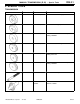
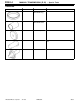
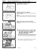
INPUT SHAFT / OUTPUT SHAFT REMOVAL
Remove the input and output shafts together.
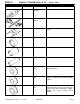
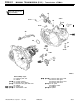
ADJUSTMENT BEFORE REASSEMBLY
SPACER SELECTION FOR DIFFERENTIAL CASE END
PLAY ADJUSTMENT
(1) Put solders (about 10 mm long, 1.6 mm in diameter) in
the illustrated positions of the transmission case and install
the differential.
(2) Install the clutch housing and tighten the bolts to the
specified torque.
(3) If the solders are not crushed, pu t larger diameter solders
and repeat Steps (1) a n d (2).
(4) Measure th e thickness (T) of the crushed solder with a
micrometer and select a spacer according to the following
equation.
Spacer thickness:
(T - 0.05 mm) to (T - 0.17 mm)
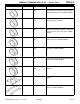
REASSEMBLY SERVICE POINTS
"
A
A
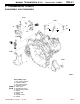
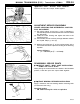
OUTPUT SHAFT / INPUT SHAFT INSTALLATION
<F5M41 with reverse brake>
While placing the reverse brake cone detent in the illustrated
position, install the input and output shafts together.
"
B
A
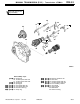
FRONT BEARING RETAINER INSTALLATION
Apply a sealant to t h e front bearing retainer mounting bolts
(countersunk bolts only).
Specified sealant:
3M STUD Locking No. 4170 or equivalent
PWEE9508-F
E
July 1999Mitsubishi Motors Corporation Revised
Output shaft
Input shaft
Solders
Detent
5mm