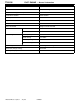
1A-0-1 ENGINE F8QT SERIES CONTENTS GENERAL INFORMATION . . . . . . . . . . . . . . . . . . . . . . . . . . . . . . . 1. SPECIFICATIONS . . . . . . . . . . . . . . . . . . . . . . . . . . . . . . . . . . . SERVICE SPECIFICATIONS . . . . . . . . . . . . . . . . . . . . . . . . TORQUE SPECIFICATIONS . . . . . . . . . . . . . . . . . . . . . . . . FORM-IN-PLACE GASKET . . . . . . . . . . . . . . . . . . . . . . . . . 2. SPECIAL TOOLS . . . . . . . . . . . . . . . . . . . . . . . . . . . . . . . . . . . . 3.
11A-0-2 NOTES E Mitsubishi Motors Corporation July 1996 PWEE9602
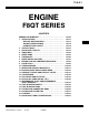
F8QT ENGINE - General Information 11A-0-3 GENERAL INFORMATION SECTIONAL VIEW OF ENGINE REN0137 E Mitsubishi Motors Corporation July 1996 PWEE9602
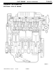
11A-0-4 F8QT ENGINE - General Information SECTIONAL VIEW OF ENGINE REN0138 E Mitsubishi Motors Corporation July 1996 PWEE9602
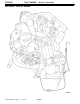
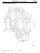
F8QT ENGINE - General Information 11A-0-5 SECTIONAL VIEW OF ENGINE REN0139 E Mitsubishi Motors Corporation July 1996 PWEE9602
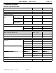
11A-0-6 F8QT ENGINE - General Information Description Specifications Type F8QT diesel engine Number and arrangement of cylinders 4 in-line Combustion chamber Swirl chamber Total displacement 1870 cm3 Cylinder bore ´ stroke 80 ´ 93 mm Compression ratio 21 Valve mechanism Single overhead camshaft Number of valves Valve timing Intake 4 Exhaust 4 Intake opening 0_ BTDC Intake closing 18_ ABDC Exhaust opening 41_ BBDC Exhaust closing 0_ ATDC Turbocharger Exhaust gas turbocharger
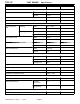
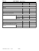
11A-1-1 F8QT ENGINE - Specifications 1. SPECIFICATIONS SERVICE SPECIFICATIONS Item Standard Limit 0.05 - Cylinder head Flatness of cylinder head surface mm Cylinder head gasket Gasket thickness mm Projecting height of piston - 0.073 Number of holes; 2 1.4 - Projecting height of piston 0.073 - 0.206 Number of holes; 1 1.5 - Projecting height of piston 0.206 - Number of holes; 3 1.6 - Class A 80.006 - 80.024 - Class B 80.256 - 80.274 - Piston-to-cylinder clearance mm 0.021 - 0.
11A-1-2 F8QT ENGINE - Specifications Item Standard Limit Intake 8.5 - Exhaust 10.34 - Camshaft end play mm 0.048 - 0.133 - Radial clearance mm 0.050 - 0.150 - Intake 0.15 - 0.25 - Exhaust 0.35 - 0.45 - Intake 0.2 - Exhaust 0.4 - Intake 36.22 - Exhaust 31.62 - Intake 60_ - Exhaust 45_ - Intake 1.8 ± 0.2 - Exhaust 1.8 - Loading 0 N 43.9 - Loading 250 N 36.8 - Loading 612 N 26.4 - Diameter (tolerance) mm 35 - Height mm 26.
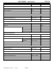
11A-1-3 F8QT ENGINE - Specifications Item Standard Limit Inner bearing mm 39.5 - Outer bearing mm 40.5 - End play mm 0.07 - 0.15 - End play mm 0.07 - 0.23 - Thrust washer thickness mm 2.30 - 2.50 - Radial clearance (main bearings) mm 0.04 - 0.07 - Ovality mm - 0.0025 Taper mm - 0.005 Standard (blue) 54.785 - 54.805 - Standard (red) 54.795 - 54.805 - Undersize 1 54.550 - 54.560 - Ovality mm - 0.0025 Taper mm - 0.005 Standard 48.00 - 48.02 - Undersize 1 47.
11A-1-4 F8QT ENGINE - Specifications Item Standard Limit - 0.07 End play mm 0.02 - 0.08 - Clearance, gears to pump body (backlash) mm 0.10 - 0.24 - Bearing clearance, drive shaft mm 0.024 - 0.49 - Number of teeth on oil pump sprocket 8 - Loading 0 N 74.6 - Loading 10.2 N 48.2 - Loading 70 N 41.2 - Oil capacity, exclusive of oil filter L 4.8 - Oil capacity, inclusive of oil filter L 5.3 - Difference between MAX-MIN marks on dipsitck L 1.
F8QT ENGINE - Specifications TORQUE SPECIFICATIONS Items Nm Crankshaft pulley Crankshaft pulley bolt 120 Timing belt Camshaft sprocket bolt 50 Water pump Water pump pulley bolt 20 Water pump bolt 12.5 Thermostat Thermostat cover bolt 10 Thermostat housing bolt 10 Bleedscrew 0.6 Glow plugs Glow plug 22.
11A-1-6 F8QT ENGINE - Specifications Items Nm Rocker cover and cylinder head Rocker cover nut 5 Cylinder head bolt 30 + 50_ ± 4_ + fully slacken + 25 + 213_ ± 2_ + (warm up) 120_ ± 7_ Camshaft, intake and exhaust valves Camshaft bearing cap bolt (M6) 10 Camshaft bearing cap bolt (M8) 20 Glow plug 22.
F8QT ENGINE - Specifications Items Nm Fuel injection pump Injection pipe union nut 22.5 Screwed sleeve/nut assembly 90 Nut 70 Injection pump bolt 22.5 Bolt 20 Pistons and connecting rods Connecting rod cap bolt 45 Flywheel Flywheel bolt 53 Crankshaft and cylinder block Main bearing cap bolt 65 Front plate bolt 12.
11A-1-8 F8QT ENGINE - Specifications FORM-IN-PLACE GASKET The engine has several areas where the form-in-place gasket (FIPG) is in use. To ensure that the gasket fully serves its purpose, it is necessary to observe some precautions when applying the gasket. Bead size, continuity and location are of paramount importance. Too thin a bead could cause leaks. Too thick a bead, on the other hand, could be squeezed out of location, causing blocking or narrowing of the fluid feed line.
F8QT ENGINE - Special Tools 11A-2-1 2.
11A-2-2 Tool E Mitsubishi Motors Corporation F8QT ENGINE - Special Tools Number Name Use MB996023 Valve seat installer Pressing in intake valve seat MB996024 Reamer Reaming valve guides MB996025 Bearing puller Removal of intermediate shaft outer bearing MB996026 Bearing puller Removal of intermediate shaft inner bearing MB996027 Bearing installer Installation of intermediate shaft inner bearing MB996028 Bearing installer Installation of intermediate shaft outer bearing MB996029 Valve
F8QT ENGINE - Special Tools Tool E Mitsubishi Motors Corporation 11A-2-3 Number Name Use MB996032 Tension gauge Measuring timing belt deflection MB996033 Tension gauge Measuring timing belt deflection MB996034 Sprocket stopper Removal of intermediate shaft sprocket MB996036 Hexagon socket Removal of injection pump sprocket screwed sleeve/nut assembly MB996037 Sprocket adapter Adjustment of fuel injection pump MB996038 Oil seal installer Installation of crankshaft oil seal (flywheel en
11A-2-4 Tool E Mitsubishi Motors Corporation F8QT ENGINE - Special Tools Number Name Use MB996042 Oil seal installer Installation of camshaft oil seal MB996043 Sprocket stopper Locking the injection pump sprocket MD998715 Pulley holder pin Retaining the camshaft sprocket (use together with MB990767) July 1996 PWEE9602
F8QT ENGINE - Crankshaft Pulley 11A-3-1 3. CRANKSHAFT PULLEY 2 120 Nm 1 REN0143 Removal steps AA" "AA 1. Crankshaft pulley bolt 2. Crankshaft pulley REMOVAL SERVICE POINT AA" CRANKSHAFT PULLEY BOLT REMOVAL Use special tool MB996015 to hold the flywheel during removal.
11A-3-2 F8QT ENGINE - Crankshaft Pulley INSTALLATION SERVICE POINT "AA CRANKSHAFT PULLEY INSTALLATION (1) Use special tool MB996015 to hold the flywheel during installation. MB996015 REN0144 (2) Apply a locking agent to the screw thread of the bolt. Tighten the bolt to the specified torque.
11A-4-1 F8QT ENGINE - Timing Belt 4. TIMING BELT REMOVAL AND INSTALLATION 50 Nm 11 10 9 12 8 13 REN0001 Removal steps 1. Bolt 2. Bolt 3. Nut 4. Engine support bracket 5. Timing gear case cover 6. Timing gear case cover 7. Timing gear case cover E Mitsubishi Motors Corporation July 1996 AA" "BA 8. AB" "AA 9. 10. 11. 12. 13.
11A-4-2 F8QT ENGINE - Timing Belt REMOVAL SERVICE POINTS AA" TIMING BELT REMOVAL (1) Turn the crankshaft clockwise so that the piston of No. 1 cylinder (flywheel end) is at TDC, with the following marks in line with each other: D flywheel/clutch housing; D rear guard plate/camshaft sprocket. Scribe a mark on the injection pump mounting bracket. (2) Insert an 8 mm diameter locking pin in the threaded hole of torx bolt 2 so that it engages the recess in the crankshaft web.
F8QT ENGINE - Timing Belt 11A-4-3 (4) Fit the timing belt so that the lines on the belt are aligned with the marks on the crankshaft and camshaft sprockets and the injection pump sprocket. NOTE D the direction of rotation of the belt (see the arrows on the belt); D the sequence in which the belt is fitted around the sprockets. REN0006 (5) Fit the special tool on the timing belt and the timing belt tensioner. (6) Tension the timing belt with the aid of an M6 bolt. Standard value: 7.
11A-4-4 F8QT ENGINE - Timing Belt (7) Abnormal wear in teeth. (8) Missing tooth. 8EN0068 TIMING BELT TENSIONER AND IDLER (1) Check that the tensioner and idler rotate smoothly without excessive play or abnormal noise. Replace them with new ones if necessary.
F8QT ENGINE - Water Pump 11A-5-1 5. WATER PUMP REMOVAL AND INSTALLATION 12.5 Nm 20 Nm Removal steps 1. V-ribbed belt (alternator & others) 2. Bolt 3. Water pump pulley 4. Bolt 5. Water pump 6.
F8QT ENGINE - Thermostat 11A-6-1 6. THERMOSTAT REMOVAL AND INSTALLATION 10 Nm 10 Nm 0.6 Nm REN0010 Removal steps 1. Bolt 2. Thermostat cover 3. Plate "AA 4. O-ring 5. Thermostat 6. Bolt 7. Thermostat housing "AA 8. O-ring 9. Bleedscrew INSTALLATION SERVICE POINT "AA O-RING INSTALLATION Caution D If O-rings are soaked in engine oil they will swell up. Keep the O-rings 4 and 8 free of engine oil when they are being fitted.
F8QT ENGINE - Water Hoses and Pipes 11A-7-1 7. WATER HOSES AND PIPES REMOVAL AND INSTALLATION REN0035 Removal steps 1. Water inlet hose 2. Water outlet hose 3. Heater inlet hose 4.
F8QT ENGINE - Engine Coolant Temperature Sensor 11A-8-1 8. ENGINE COOLANT TEMPERATURE SENSOR REMOVAL AND INSTALLATION REN0036 Removal steps 1. Wiring harness connector 2. Retaining clip 3. Temperature sensor, ECU 4.
11A-9-1 F8QT ENGINE - Glow Plugs 9. GLOW PLUGS REMOVAL AND INSTALLATION 22.5 Nm 5 Nm REN0037 Removal steps 1. Nut 2. Glow plug leads, Nos. 1 and 2 3. Glow plug leads, Nos. 3 and 4 4.
11A-10-1 F8QT ENGINE - Turbocharger 10. TURBOCHARGER REMOVAL AND INSTALLATION 25 Nm 28.7 Nm 45 Nm 35 Nm 45 Nm 25 Nm 25 Nm 8 Nm REN0038 Removal steps 1. Vacuum hose 2. Oil supply pipe 3. Oil return pipe 4. Nut 5. Banjo bolt 6. Coolant supply pipe 7. 8. 9. 10. "AA 11.
F8QT ENGINE - Intake and Exhaust Manifolds 11A-11-1 11. INTAKE AND EXHAUST MANIFOLDS REMOVAL AND INSTALLATION 19.5 Nm 19.5 Nm 8 Nm 30 Nm 25 Nm REN0039 Removal steps 1. Vacuum hose 2. EGR valve 3. EGR pipe 4. Oil pipe from turbocharger 5. Vacuum hose to turbocharger E Mitsubishi Motors Corporation July 1996 6. 7. 8. 9. 10.
11A-12-1 F8QT ENGINE - Rocker Cover and Cylinder Head 12. ROCKER COVER AND CYLINDER HEAD REMOVAL AND INSTALLATION 5 Nm REN0040 Removal steps 1. Engine hanger 2. Thermostat housing 3. Vacuum pump 4. Oil filler cap 5. Nut 6. Rocker cover "DA 7. Rocker cover gasket E Mitsubishi Motors Corporation July 1996 "CA 8. 9. AA" "BA 10. AB" "AA 11.
11A-12-2 F8QT ENGINE - Rocker Cover and Cylinder Head REMOVAL SERVICE POINTS AA" CYLINDER HEAD REMOVAL (1) Release and then remove the cylinder head bolts. (2) Lift the cylinder head straight up over the locating dowels and then remove the cylinder head. REN0041 AB" CYLINDER HEAD GASKET REMOVAL Caution D When removing the cylinder head gasket, take care not to scratch the cylinder head or cylinder block gasket faces.
F8QT ENGINE - Rocker Cover and Cylinder Head 11A-12-3 "BA CYLINDER HEAD INSTALLATION (1) Select a suitable cylinder head gasket 11. (2) Rotate the crankshaft so that the piston of No. 1 cylinder is positioned a quarter-stroke past TDC. (3) Fit the cylinder head over the locating dowels. "CA CYLINDER HEAD BOLT INSTALLATION (1) When installing the cylinder head bolts, check that the length of the shank of each bolt (without the washer) is within the limit value.
11A-12-4 F8QT ENGINE - Rocker Cover and Cylinder Head "DA ROCKER COVER GASKET INSTALLATION (1) Lightly smear the corners of the rocker cover gasket with a sealant. (2) Locate the gasket on the rocker cover. (3) Fit the rocker cover. Caution D Make sure the gasket is still properly located.
11A-13-1 F8QT ENGINE - Camshaft, Intake and Exhaust Valves 13. CAMSHAFT, INTAKE AND EXHAUST VALVES REMOVAL AND INSTALLATION 10 Nm 20 Nm 70 Nm 22.5 Nm Lubricate all internal parts with engine oil during reassembly. REN0048 "FA "FA "FA "FA "FA "HA AA" "EA AB" "DA Removal steps 1. Bolt 2. No. 1 camshaft bearing 3. No. 2 camshaft bearing 4. No. 3 camshaft bearing 5. No. 4 camshaft bearing 6. No. 5 camshaft bearing 7. Camshaft 8. Oil seal 9. Tappet pad 10. Tappet 11. Retainer locks 12.
11A-13-2 F8QT ENGINE - Camshaft, Intake and Exhaust Valves REMOVAL SERVICE POINTS AA" RETAINER LOCKS REMOVAL (1) Fit valve spring compressor MB996014 on the cylinder head 31 as shown in the illustration. (2) Press down the valve spring retainer 12 and remove the retainer locks 11. MB996014 REN0049 AB" VALVE STEM SEAL REMOVAL Remove the seal 15 with valve stem seal remover MB996021. MB996021 REN0050 AC" VALVE GUIDE REMOVAL (1) Support the cylinder head 31.
F8QT ENGINE - Camshaft, Intake and Exhaust Valves 11A-13-3 (3) Tap the valve seat through the passage and out of the cylinder head using a long drift. REN0054 AE" SWIRL CHAMBER REMOVAL (1) Insert a round rod in the glow plug hole. Remove the swirl chamber by tapping the rod with a hammer. REN0055 INSPECTION CAMSHAFT End play (1) Measure the end play. Fit a new cylinder head if the measured value deviates from the specified value.
11A-13-4 F8QT ENGINE - Camshaft, Intake and Exhaust Valves INTAKE AND EXHAUST VALVES Examining the valve stem for wear (1) Replace the valve if the valve stem diameter is smaller than the limit value or if there is evidence of uneven wear. NOTE If the valve 16, 17 is new, it should be matched with the valve seat 24, 25 by grinding them together. 4ME0122 Valve seat angle and valve seat margin (1) Replace the valve 16, 17 if the limit value is exceeded after correcting the valve seat angle.
F8QT ENGINE - Camshaft, Intake and Exhaust Valves A B D 11A-13-5 VALVE SEAT Valve seat width (1) Replace the valve seat 24, 25 if the limit value is exceeded. Angle A: intake valve seat: 60_ exhaust valve seat: 45_ The contact surface B must be 1.7 ± 0.1 mm. If the contact surface is too wide, correct this with a valve seat cutter.
11A-13-6 F8QT ENGINE - Camshaft, Intake and Exhaust Valves 16, 17 C A 4ME0131 VALVE AND VALVE SEAT (1) The valve and the valve seat must be lapped as follows: (a) Smear a thin layer of lapping compound evenly on the valve seating surface A of the valve seat 24, 25. Caution D Make sure that no lapping compound is smeared on the stem C of the valve 16, 17. D First use an average grade lapping compound (120-150) and then a finer grade (more than 200).
F8QT ENGINE - Camshaft, Intake and Exhaust Valves 11A-13-7 (3) Heat the cylinder head to about +100_C. REN0067 3 - 4 sec. REN0068 (4) Install the intake valve seat on valve seat installer MB996022 and exhaust valve seat on valve seat installer MB996023. (5) Immerse the valve seats 24, 25 in liquid nitrogen so as to cool them sufficiently. (6) Pressing the valve seats 24, 25 with the valve seat installers MB996022 and MB996023 in the bores until they abut in the cylinder head.
11A-13-8 F8QT ENGINE - Camshaft, Intake and Exhaust Valves (6) Clean the valve guide inner bores 22, 23 with reamer MB996024. MB996024 REN0072 "DA VALVE STEM SEAL INSTALLATION (1) Lubricate the valve guides 22, 23 with engine oil. Introduce the valves 16, 17 through the valve guides. Locate the protective plastic cap over the valve stem. (2) Locate the valve stem oil seal 15. Press in the valve stem oil seal 15 vertically until it abuts the cylinder head 31 with valve stem seal installer MB996031.
11A-13-9 F8QT ENGINE - Camshaft, Intake and Exhaust Valves "GA SWIRL CHAMBER INSTALLATION NOTE First check that the dowel pin is still in the swirl chamber. If the dowel pin is no longer present, a new swirl chamber 26 will have to be fitted. MB996018 REN0077 (1) Measure the difference in height between the swirl chambers and the cylinder head with slip gauge MB996018 and dial indicator. The difference in height must be between 0.01 and 0.04 mm. (2) Fit the glow plugs 18 and connect up the wiring.
11A-14-1 F8QT ENGINE - Vacuum Pump 14. VACUUM PUMP REMOVAL AND INSTALLATION 22 Nm 22 Nm REN0083 Removal steps 1. Vacuum hose 2. Bolt 3. Washer 4. Vacuum pump 5.
11A-15-1 F8QT ENGINE - Oil Cooler and Oil Filter 15. OIL COOLER AND OIL FILTER REMOVAL AND INSTALLATION Lubricate all internal parts with engine oil during reassembly. 35 Nm 60 Nm REN0085 60 Nm Removal steps "AA 1. Oil filter 2. Nut 3. Thermostat housing 4. O-ring 5. Plug 6. Sealing washer AA" 7. 8. 9. 10. 11. 12. Thermostat Spring Nut Oil cooler O-ring O-ring REMOVAL SERVICE POINTS AA" THERMOSTAT REMOVAL (1) Remove the socket-head screw and sealing washer.
F8QT ENGINE - Oil Pan, Oil Pump and Oil Jets 11A-16-1 16. OIL PAN, OIL PUMP AND OIL JETS REMOVAL AND INSTALLATION Lubricate all internal parts with engine oil during reassembly. 20 Nm 22 Nm 12 Nm 13 Nm 25 Nm Removal steps 1. Drain plug 2. Bolt "AA 3. Oil pan 4. Bolt 5. Oil pump body 6. Bolt 7. Cover E Mitsubishi Motors Corporation July 1996 REN0084 8. 9. 10. 11. 12. 13. 14.
11A-16-2 F8QT ENGINE - Oil Pan, Oil Pump and Oil Jets INSTALLATION SERVICE POINTS A REN0088 "AA OIL PAN INSTALLATION (1) When applying sealant, make sure that the cartridge nozzle opening is not larger than 4 mm. (2) Apply an even, uninterrupted bead of sealant A to the entire circumference of the oil pan flange 3 as shown in the illustration. (3) Install the oil pan 3. Caution D Make sure that the surface to which the sealant A is applied is free of dirt and other impurities.
F8QT ENGINE - Intermediate Shaft and Intermediate Shaft Bearings 11A-17-1 17. INTERMEDIATE SHAFT AND INTERMEDIATE SHAFT BEARINGS Lubricate all internal parts with engine oil during reassembly. 15 Nm 15 Nm 15 Nm 50 Nm REN0091 Removal steps 1. Timing belt 2. Bolt AA" "EA 3. Intermediate shaft sprocket 4. Bolt 5. Cover 6. O-ring AB" 7. Oil pump drive gear 8. Bolt E Mitsubishi Motors Corporation July 1996 9. "DA 10. 11. "CA 12. "CA 13. AC" "BA 14. AD" "AA 15.
11A-17-2 F8QT ENGINE - Intermediate Shaft and Intermediate Shaft Bearings REMOVAL SERVICE POINTS MB996034 AA" INTERMEDIATE SHAFT SPROCKET REMOVAL (1) Use sprocket stopper MB996034 to hold the sprocket during removal. (2) Remove the sprocket and the sprocket key. REN0146 AB" OIL PUMP DRIVE GEAR REMOVAL (1) Remove the oil pump drive gear 7 with the aid of an M12 bolt. REN0092 AC" OUTER BEARING REMOVAL (1) Remove the outer bearing 14 with bearing puller MB996025.
F8QT ENGINE - Intermediate Shaft and Intermediate Shaft Bearings MB996028 11A-17-3 "BA OUTER BEARING INSTALLATION (1) Install the outer bearing with the aid of bearing installer MB996028. The pin of the installer must engage the oil return passage of the intermediate shaft 13. NOTE Position the outer bearing with the opening at the mark on the installer. REN0096 (2) Check with a piece of wire (1.2 mm diameter) that the oil hole is aligned with the drilling in the bearing.
F8QT ENGINE - Fuel Injection Nozzle 11A-18-1 18. FUEL INJECTION NOZZLE REMOVAL AND INSTALLATION 22.5 Nm 70 Nm 70 Nm REN0099 Removal steps 1. Injection pipe 2. Fuel return pipe AA" "AA 3. Fuel injection nozzle assembly 4. Heat shield 5. Nozzle body 6. Washer 7. Push rod AB" 8. 9. 10. 11. 12. 13. Spring Shim Needle valve Nozzle tip Retaining nut Nozzle needle lift sensor (for No. 1 cylinder only) AA" FUEL INJECTION NOZZLE REMOVAL (1) Remove the fuel injection nozzle with special socket MB996041.
11A-18-2 F8QT ENGINE - Fuel Injection Nozzle INSPECTION FUEL INJECTION NOZZLE (1) Connect the nozzle tester to injection nozzle 3 and carry out the tests described below. Caution D Before starting the tests, operate the lever of the nozzle tester two or three times to bleed air from the nozzle. 4ME0206 A B C D 4ME0207 Valve opening pressure test (1) Slowly push down the nozzle tester lever. The pressure gauge pointer will gradually rise and then deflect suddenly at a certain value.
F8QT ENGINE - Fuel Injection Nozzle 11A-18-3 Leakage test (1) Increase the pressure to 11 MPa by operating the lever of the nozzle tester. Maintain the pressure for 10 seconds. No fuel must dribble out of the nozzle during this test. (2) If dribbling starts within this 10 second period, disassemble and clean the injection nozzle 3 and repeat the test. Fit a new injection nozzle if the problem persists.
11A-18-4 F8QT ENGINE - Fuel Injection Nozzle (c) Clean the seating E of the nozzle tip 11 with the special scraper tool F. Caution D Take care not to damage the seating face. F (d) Use Fuso carbon deposit cleaning agent to remove encrusted carbon deposits. E 4ME0212 (e) Remove the carbon deposits in the injection hole of the nozzle tip 11 by rotating the needle cleaner H (special tool) in the injection hole J. H Diameter of cleaning needle: less than 1.
F8QT ENGINE - Fuel Injection Pump 11A-19-1 19. FUEL INJECTION PUMP 22.5 Nm 20 Nm 22.5 Nm 1 70 Nm 90 Nm REN0101 Removal steps 1. Screwed sleeve/nut assembly 2. Flange 3. Nut 4. Washer AA" "AA 5. Sprocket 6. Injection pipe 7. Throttle cable 8. Fuel return pipe 9. Fuel supply pipe E Mitsubishi Motors Corporation July 1996 AB" PWEE9602 10. 11. 12. 13. 14. 15. 16. 17.
11A-19-2 F8QT ENGINE - Fuel Injection Pump REMOVAL SERVICE POINTS MB996043 MB996036 REN0102 AA" SPROCKET REMOVAL (1) Locate the sprocket stopper MB996043 between the pump bracket and the sprocket. Fasten the tool with the bolts supplied with the set. (2) Remove the screwed sleeve and nut assembly with hexagon socket spanner MB996036 (release by turning clockwise). (3) Remove the nut. (4) Pull the sprocket off the shaft with a gear puller. Remove the locking tool.
F8QT ENGINE - Fuel Injection Pump 11A-19-3 FUEL INJECTION TIMING CHECK MEASURING TOOL INSTALLATION (1) Turn the crankshaft clockwise so that the piston of No. 1 cylinder (flywheel end) is at TDC, with the following marks in line with each other: D flywheel/clutch housing D timing belt cover/camshaft sprocket. REN0148 (2) Turn the crankshaft (clockwise) 1 3/4 revolutions. (3) Remove the plug A. (4) Fit measuring device adaptor MB996030: D Locate the guide bush B in the pump.
11A-19-4 F8QT ENGINE - Fuel Injection Pump FUEL INJECTION PUMP ADJUSTMENT MEASURING TOOL INSTALLATION (1) Turn the crankshaft clockwise so that the piston of No. 1 cylinder (flywheel end) is at TDC, with the following marks in line with each other: D flywheel/clutch housing D timing belt cover/camshaft sprocket. REN0148 (2) Remove cover 1 and the bolts of cover 2. REN0153 (3) Locate sprocket stopper MB996043 between the pump bracket and the sprocket.
F8QT ENGINE - Fuel Injection Pump 11A-19-5 (5) Turn the crankshaft (clockwise) 1 3/4 revolutions. (6) Remove the plug A. (7) Fit measuring device adaptor MB996030. D Locate the guide bush B in the pump. D Slide the measuring pin C, which is part of the measuring tool, into the guideway of the pump. D Locate and secure the holder D. (8) Position the clock gauge E and make sure that the plunger is pressed in at least 0.2 mm. Secure the clock gauge and set it at zero.
11A-19-6 F8QT ENGINE - Fuel Injection Pump (11)Locate sprocket stopper MB996043. Fix the bracket with the two bolts supplied with the set. Secure the bracket with bolt F so that it is free from play. Caution The pump sprocket must not be displaced (the pointer of the micrometer must not move). REN0160 70 Nm REN0161 (12)Insert Hexagon socket spanner MB996036 in the nut assembly and tighten the assembly steadily (turning counter-clockwise) to 70 Nm.
F8QT ENGINE - Pistons and Connecting Rods 11A-20-1 20. PISTONS AND CONNECTING RODS REMOVAL AND INSTALLATION Lubricate all internal parts with engine oil during reassembly. 45 Nm REN0110 Removal steps 1. Bolt 2. Connecting rod cap "AA 3. Connecting rod lower bearing (big-end bearing) "AA 4. Connecting rod upper bearing (big-end bearing) "BA 5.
11A-20-2 F8QT ENGINE - Pistons and Connecting Rods CONNECTING ROD BEARINGS Caution D Do not fit old connecting rod bearings 3, 4 if they are badly worn. D If any one of the connecting rod bearings 3, 4 is defective, the bearings should be replaced as a set. 4 3 4ME0241 Clearance between connecting rod and crankshaft (1) Replace the part in question if the clearance exceeds the limit value. 4ME0242 PISTON/CONNECTING ROD AND CYLINDER BLOCK (1) Measure the cylinder bores.
F8QT ENGINE - Pistons and Connecting Rods 11A-20-3 "BA PISTON AND CONNECTING ROD INSTALLATION Caution D Ensure that the piston ring gaps A are correctly positioned. D Take care not to damage the piston crown (combustion chamber) B. D Take care not to strike the connecting rod against the oil jet. top REN0113 45 mm (1) Lightly coat the big-end journal, cylinder wall and piston with engine oil. (2) Fit the connecting rod with the mark facing towards the intermediate shaft side.
F8QT ENGINE - Pistons and Piston Pins 11A-21-1 21. PISTONS AND PISTON PINS REMOVAL AND INSTALLATION Lubricate all internal parts with engine oil during reassembly. REN0115 AA" "BA AB" "AA AB" "AA AB" "AA Removal steps 1. Circlip 2. Piston pin 3. Connecting rod 4. Piston ring No. 1 5. Piston ring No. 2 6. Oil ring 7. Piston REMOVAL SERVICE POINTS AA" PISTON PIN REMOVAL (1) Remove the circlips. (2) Remove the piston pin 2.
11A-21-2 F8QT ENGINE - Pistons and Piston Pins AB" PISTON RING REMOVAL MH060014 03638 INSPECTION PISTON PIN/CONNECTING ROD/PISTON (1) Measure the clearance between the piston pin 2 and the piston 7. Replace the part in question if the clearance exceeds the limit value. 7 2 4ME0256 PISTON RING GAP (1) Insert the piston rings 4, 5, 6 in the cylinder bore of the cylinder block with the aid of the piston 7. (2) Hold the piston rings 4, 5, 6 in this position and measure the ring gap with a feeler gauge.
F8QT ENGINE - Pistons and Piston Pins 11A-21-3 CURVATURE AND TWIST OF CONNECTING ROD (1) Measure the curvature and the twist of the connecting rod 3. Replace the connecting rod if the limit values are exceeded. Alignment gauge REN0118 Caution D Installed connecting rod 3, with upper and lower connecting rod bearings in place, in the connecting rod alignment tool. D Tighten the connecting rod cap in accordance with the specified procedure.
11A-22-1 F8QT ENGINE - Flywheel 22. FLYWHEEL REMOVAL AND INSTALLATION 53 Nm REN0120 Removal steps AA" "BA 1. Bolt AB" "AA 2. Flywheel ring gear 3. Flywheel REMOVAL SERVICE POINTS AA" FLYWHEEL REMOVAL Use flywheel stopper MB996015 to hold the flywheel during removal. MB996015 REN0147 AB" FLYWHEEL RING GEAR REMOVAL (1) Examine the flywheel ring gear 2 for damage and abnormal wear and replace if necessary.
11A-22-2 F8QT ENGINE - Flywheel INSPECTION FLYWHEEL Axial throw (1) If the axial throw exceeds the limit value, check the flywheel for a loose bolt 1 or for a defective connection to the crankshaft. Repair or replace as necessary. REN0122 Deformation of the friction surface (1) If necessary, replace the flywheel 3. NOTE A new flywheel is always supplied complete with the ring gear.
F8QT ENGINE - Crankshaft and Cylinder Block 11A-23-1 23. CRANKSHAFT AND CYLINDER BLOCK REMOVAL AND INSTALLATION 65 Nm 12.5 Nm Lubricate all internal parts with engine oil during reassembly. "CA "DA AA" "BA "AA "BA "BA "EA REN0124 Removal steps 1. Bolt 2. Front plate 3. Oil seal 4. Bolt 5. Main bearing cap 6. Crankshaft 7. Thrust bearing 8. Crankshaft main bearing, lower 9. Crankshaft main bearing, upper 10.
11A-23-2 F8QT ENGINE - Crankshaft and Cylinder Block REMOVAL SERVICE POINTS AA" MAIN BEARING CAP REMOVAL (1) Remove the retaining bolts. NOTE To remove No. 1 bearing cap (flywheel end) with screwdrivers, two M7 bolts must be fitted in the bearing cap and two M7 bolts in the cylinder block. REN0125 INSPECTION CRANKSHAFT Ovality and taper of main bearing journals and big-end bearing journals (1) Replace the crankshaft if the limit value is exceeded.
F8QT ENGINE - Crankshaft and Cylinder Block 11A-23-3 INSTALLATION SERVICE POINTS "AA THRUST WASHER INSTALLATION (1) Fit the thrust washers 7 at No. 2 journal on the crankshaft 6. Caution D Fit the thrust washers 7 with the oil grooves A facing outwards. REN0130 "BA CRANKSHAFT MAIN BEARING / MAIN BEARING CAPS INSTALLATION Caution D The main bearing caps are marked. 65 Nm (1) Start by installing bearing cap No. 2. The bolts should be tightened to the specified torque.
11A-23-4 F8QT ENGINE - Crankshaft and Cylinder Block MB996040 "DA CRANKSHAFT FRONT OIL SEAL INSTALLATION (1) Coat the lip of the oil seal with a thin layer of engine oil. (2) Locate the oil seal installer guide MB996040 over the crankshaft. (3) Locate the oil seal over the oil seal installer guide. (4) Fit the oil seal with oil seal installer MB996040. REN0135 "EA CRANKSHAFT REAR OIL SEAL INSTALLATION (1) Coat the lip of the oil seal with a thin layer of engine oil.
NOTES