23D-1-1 R4A51, V4A51 - Specifications 1.
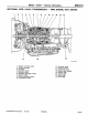
23D-14-1 R4A51, V4A51 - Transfer 14. TRANSFER DISASSEMBLY AND ASSEMBLY - V4A51-4 PART TIME 4WD 35 Nm 9 34 Nm 34 Nm 3 10 11 4 5 35 Nm 1 6 7 8 2 12 35 Nm 13 Apply gear oil to all moving parts before installation. 14 15 Disassembly steps 1. 2-4WD detection switch 2. Gasket 3. H-L detection switch 4. Gasket 5. Steel ball "LA 6. Plug "PA 7. Spring 8. Steel ball E Mitsubishi Motors Corporation July 2000 "LA 9. "PA 10. 11. "LA 12. "LA 13. 14. "OA 15.
23D-14-3a R4A51, V4A51 - Transfer DISASSEMBLY AND ASSEMBLY - V4A51-5 PART TIME 4WD 35 Nm 9 34 Nm 34 Nm 3 10 11 4 5 35 Nm 1 6 7 8 2 12 35 Nm 13 Apply gear oil to all moving parts before installation. 14 15 Disassembly steps 1. 2-4WD detection switch 2. Gasket 3. H-L detection switch 4. Gasket 5. Steel ball "LA 6. Plug "PA 7. Spring 8. Steel ball E Mitsubishi Motors Corporation July 2000 "LA 9. "PA 10. 11. "LA 12. "LA 13. 14. "OA 15.
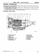
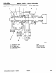
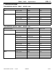
23D-14-3b R4A51, V4A51 - Transfer 21 Nm 18 Nm 32 33 35 Nm 26 29 25 35 Nm 28 27 23 34 35 Nm 22 30 31 16 24 20 17 35 Nm 21 32 Nm 35 Nm Apply gear oil to all moving parts before installation. 19 18 35 Nm Disassembly steps "NA 16. Transfer case plate 17. Needle bearing 18. Countershaft gear "MA 19. Spacer "LA 20. Plug "KA 21. H-L shift rail plug 22. Low switch 23. Gasket 24. Dynamic damper 25. Harness bracket E Mitsubishi Motors Corporation July 2000 "JA "IA "IA "HA "QA "GA 26.
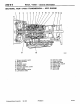
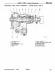
23D-14-3c R4A51, V4A51 - Transfer 47 44 45 44 43 35 Nm 46 40 39 42 35 41 49 48 8.8 Nm 51 36 52 50 37 38 54 Apply gear oil to all moving parts before installation. 55 53 AA" "EA AA" "DA "DA "CA Disassembly steps 35. H-L shift rail 36. Chain cover 37. H-L shift fork 38. H-L clutch sleeve 39. Interlock plunger 40. Spring pin 41. 2-4WD shift lug 42. Distance piece 43. E-clip 44. Spring seat 45.
23D-14-3d R4A51, V4A51 - Transfer DISASSEMBLY AND ASSEMBLY - V4A51-7 PART TIME 4WD 35 Nm 9 10 1 11 34 Nm 3 35 Nm 6 7 8 2 34 Nm 4 15 5 12 14 35 Nm 13 18 Nm 16 17 35 Nm Disassembly steps 1. 4WD switch 2. Gasket 3. Transfer switch 4. Gasket 5. Steel ball "LA 6. Plug "PA 7. Spring 8. Steel ball "LA 9. Plug E Mitsubishi Motors Corporation July 2000 35 Nm "PA 10. 11. "LA 12. "LA 13. 14. 15. 16. 17. PWEE8920-J Apply gear oil to all moving parts before installation.
23D-14-3e R4A51, V4A51 - Transfer 35 Nm 18 Nm 24 27 25 29 26 30 35 Nm 23 28 18 35 Nm 22 19 35 Nm 32 Nm Apply gear oil to all moving parts before installation. 21 20 35 Nm Disassembly steps "NA 18. Transfer case plate 19. Needle bearing 20. Countershaft gear "MA 21. Spacer "LA 22. Plug "KA 23. H-L shift rail plug 24. Low switch E Mitsubishi Motors Corporation July 2000 "JA "HA "GA "FA "EA PWEE8920-J 25. 26. 27. 28. 29. 30.
23D-14-3f R4A51, V4A51 - Transfer 43 42 38 40 41 39 40 35 Nm 44 35 36 31 45 37 33 32 46 Apply gear oil to all moving parts before installation. 34 49 47 AA" "EA AA" "DA "DA "CA Disassembly steps 31. H-L shift rail 32. Chain cover 33. H-L shift fork 34. H-L clutch sleeve 35. Interlock plunger 36. Spring pin 37. 2-4WD shift lug 38. Distance piece 39. E-clip 40. Spring seat E Mitsubishi Motors Corporation July 2000 48 AB" "BA AB" "BA AB" "BA "AA PWEE8920-J 41. 42. 43. 44. 45.
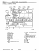
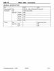
23D-14-9 R4A51, V4A51 - Transfer "QA OIL COVER INSTALLATION Install the oil cover so that the oil hole is located as shown in the illustration. Oil hole Oil cover INSPECTION 2-4WD, H-L DETECTION SWITCH Check for the continuity between the connector terminal and switch body. Switch state Continuity Switch end pressed No Switch end released Yes LOW RANGE OPERATION DETECTION SWITCH Check for the continuity between the connector terminal and switch body.
23D-15-1 R4A51, V4A51 - Transfer Case Plate 15. TRANSFER CASE PLATE DISASSEMBLY AND ASSEMBLY 18 Nm Apply gear oil to all moving parts before installation. 1 2 3 6 5 4 Disassembly steps "BA 1. Bolt 2. Bearing retainer 3. Transfer input gear "AA 4. Oil seal 5. Baffle plate 6.
R4A51, V4A51 - Rear Output Shaft 23D-18-1 18. REAR OUTPUT SHAFT DISASSEMBLY AND ASSEMBLY 18 3 4 255 Nm 2 1 9 5 6 13 8 7 10 11 12 Apply gear oil to all moving parts before installation. 14 16 15 17 Disassembly steps 1. Snap ring 2. Clutch hub 3. Low speed gear 4. Needle bearing AB" "DA 5. Jam nut AC" "CA 6. Ball bearing 7. Oil guide 8. Sprocket spacer 9. Steel ball "FA AA" "EA E Mitsubishi Motors Corporation July 2000 10. 11. 12.
23D-18-2 R4A51, V4A51 - Rear Output Shaft DISASSEMBLY AND ASSEMBLY 21 22 23 24 25 3 2 255 Nm 9 4 7 1 5 10 12 6 8 19 20 16 10 18 11 13 15 Apply gear oil to all moving parts before installation. 14 17 "FA AA" "EA AB" "DA AC" "CA Disassembly steps 1. Snap ring 2. Clutch hub 3. Low speed gear 4. Needle bearing 5. Snap ring (V4A51-7) 6. Rotor (V4A51-7) 7. Steel ball 8. Jam nut 9. Ball bearing 10.
R4A51, V4A51 - Speedometer Gear 23D-20-1 20. SPEEDOMETER GEAR DISASSEMBLY AND ASSEMBLY Apply gear oil to all moving parts before installation. 1 3 2 5 4 Disassembly steps 1. O-ring "AA 2. Spring pin 3. Driven gear 4. O-ring 5. Sleeve Slit Spring pin E Mitsubishi Motors Corporation July 2000 ASSEMBLY SERVICE POINT "AA SPRING PIN INSTALLATION Drive the spring pin in, while making sure that slit does not face gear shaft.