For A Ethernet Interface Module User’s Manual (Hardware) AJ71E71N-B5T, A1SJ71E71N-B5T AJ71E71N-B2, A1SJ71E71N-B2 Thank you for buying the Mitsubishi general-purpose programmable logic controller MELSEC-A Series Prior to use, please read both this manual and detailed manual thoroughly and familiarize yourself with the product.
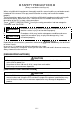
! SAFETY PRECAUTIONS ! (Always read before starting use) When using Mitsubishi equipment, thoroughly read this manual and the associated manuals introduced in the manual. Also pay careful attention to safety and handle the module properly. These precautions apply only to the installation of Mitsubishi equipment and the wiring with the external device. Refer to the user’s manual of the CPU module to be used for a description of the PLC system safety precautions.
[INSTALLATION PRECAUTIONS] CAUTION ! Install so that the tabs at the bottom of the module fit securely into the base unit mounting holes. (The AnS series module shall be fastened by screws in the base unit at the specified torque.) Not installing the module correctly could result in erroneous operation, damage, or pieces of the product falling. ! Tighten the screw within the range of specified torque. If the screws are loose, it may result in fallout, short circuits or malfunction.
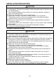
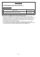
Revisions The manual number is given on the bottom left of the back cover. Print Date Jan., 2002 Manual Number IB(NA)-0800203-A Revision First printing This manual confers no industrial property rights or any rights of any other kind, nor does it confer any patent licenses. Mitsubishi Electric Corporation cannot be held responsible for any problems involving industrial property rights which may occur as a result of using the contents noted in this manual.
CONTENTS 1. 2. 3. 4. Overview............................................................................................................................. 1 Performance Specifications................................................................................................ 2 Settings and Names of Each Part ...................................................................................... 4 Loading and Installation....................................................................................
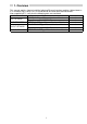
About the Manuals The following product are available for this equipment. Refer to the table given below to choose suitable manuals. Related Manual Manual name For A Ethernet Interface Module User’s Manual Manual No.
1. Overview This manual explains how to install the following Ethernet interface modules (abbreviated as E71 hereafter) for A series PLC CPU and how to wire them with external devices. After unpacking E71, verify that the following parts are contained. Model name Product name No.
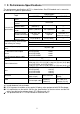
2. Performance Specifications The performance specifications of E71 is shown below. See CPU module user’s manual to be used for E71 general specifications. Topic Data transmission speed Transmission method Maximum distance between nodes Transmission Maximum segment specifications length Specifications 10BASE2 10BASE5 10 Mbps Base band 2500 m (8202.10 ft.) 925 m (3034.77 ft.) 500 m (1640.42 ft.) 185 m (606.96 ft.
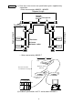
Notes (1) Each item in the transmission specifications gives supplementary explanation. • When connected by 10BASE2, 10BASE5 Segment length Node Transceiver Terminator Node Node Repeater Maximum distance between nodes Node Node • When connected by 10BASE-T Hub Maximum 100 m (328.1 ft.) Cascade connection is a maximum of 4 stages Maximum 100 m (328.1 ft.) E71 (2) Hardware specifications for E71 are based on IEEE802.3.
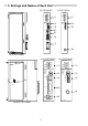
3. Settings and Names of Each Part AJ71E71N-B5T AJ71E71N-B2 AJ71E71N-B5T A J71E71N-B2 BUF1 BUF2 BUF3 BUF4 BUF5 BUF6 BUF7 BUF8 RUN RDY BSY SW.ERR. COM.ERR. CPU R/W BUF1 BUF2 BUF3 BUF4 BUF5 BUF6 BUF7 BUF8 RUN RDY BSY SW.ERR. COM.ERR. CPU R/W 1) TEST TEST ERR. 34 5 OFF ON SW1 SW2 SW3 SW4 SW5 SW6 SW7 SW8 MODE BCD 89 67 A 89 67 A 0:ONLINE 1:OFFLINE 2:TEST1 3:TEST2 4:TEST3 2) 34 5 01 EF 2 2) 01 EF 2 MODE BCD 0:ONLINE 1:OFFLINE 2:TEST1 3:TEST2 4:TEST3 1) TEST TEST ERR.
No 1) 2) 3) 4) Designation Display LED Operation mode setting switch Exchange condition setting switch 10BASE-T connector 5) External power supply indicator lamp 6) External power supply terminal 7) AUI cable connector 8) 10BASE2 connector Contents Refer to (1) Refer to (2) Refer to (3) Connector for connecting the E71 to the 10BASE-T. Lamp for verifying if power is being supplied to the transceiver when used as 10BASE5.
Remark The order of the display LEDs is shown below. AJ71E71N-B5T,AJ71E71N-B2 A1SJ71E71N-B5T,A1SJ71E71N-B2 RUN RDY BSY SW.ERR. COM.ERR. TEST TEST ERR. CPU R/W BUF1 BUF2 BUF3 BUF4 BUF5 BUF6 BUF7 BUF8 RUN RDY BSY SW.ERR. COM.ERR. CPU R/W BUF1 BUF2 BUF3 BUF4 BUF5 BUF6 BUF7 BUF8 TEST TEST ERR. (2) Operation mode setting switch setting Set the E71 operation mode.
(3) Communications exchange condition setting switch setting Set the conditions for data communication with other nodes. Communications exchange condition Switch setting switch Setting designation SW1 Line processing selection during TCP timeout error SW2 Data code setting OFF ON SW1 SW2 SW3 SW4 SW5 SW6 SW7 SW8 SW3 to SW6 SW7 SW8 — Setting contents Selects the line processing when the TCP ULP time out error occurrence. ( 1) OFF Close the circuit. ON Do not close the circuit.
4. Loading and Installation The following is explanations of the handling precautions and installation environment which is common to modules when handling E71 from unpacking to installation. For the details of loading and installation of the module, refer to User’s Manual of CPU module to be used. 4.1 Handling Precautions The following is an explanation of handling precautions of the module. (1) Because the case of the module is made of resin, be careful not to drop it or expose it to strong impact.
5. Connection to a Network The following is an explanation of the connection method of the E71 to the 10 BASE-T, 10BASE5 or the 10BASE2. Point (1) Installation procedures of the network require sufficient safety measures. For the execution of such operations as terminal processing of connection cable, trunk line cable etc., please consult with a trained professional.
5.1 Connecting to the 10BASE-T (AJ71E71N-B5T, A1SJ71E71N-B5T) 1) Connect the twisted pair cable and the hub. 2) Connect the twisted pair cable to the E71. For AJ71E71N-B5T 5.2 Connecting to the 10BASE5 (AJ71E71N-B5T, A1SJ71E71N-B5T) ( 1) 1) Slide the retainer toward the direction A as shown in the figure. 2) Push in the AUI cable connector all the way. 3) Slide the retainer toward the direction B as shown in the figure. 4) Confirm that the AUI cable is locked.
6. External Dimensions (1) AJ71E71N-B5T A J71E71N-B5T RUN BUF1 BUF2 BUF3 BUF4 BUF5 BUF6 BUF7 BUF8 RDY BSY SW.ERR. COM.ERR. CPU R/W TEST TEST ERR. 89 67 A 0 EF 12 MODE BCD 0:ONLINE 1:OFFLINE 2:TEST1 3:TEST2 4:TEST3 345 OFF ON 250 (9.84) SW1 SW2 SW3 SW4 SW5 SW6 SW7 SW8 10BASE-T ( 1) R1 EXT.PW EXT.PW (FG) 10BASE5 R2 ( 2) 106 (4.17) 13.8 (0.52) 37.5 (1.
(2) A1SJ71E71N-B5T A1SJ71E71N-B5T BUF1 BUF2 BUF3 BUF4 BUF5 BUF6 BUF7 BUF8 0:ONLINE 1:OFFLINE 2:TEST1 3:TEST2 4:TEST3 MODE 6789A BCD EF012 345 ( 1) RUN RDY BSY SW.ERR. COM.ERR. TEST TEST ERR. CPU R/W 10BASET 130 (5.12) OFF ON R1 10BASE5 R2 ( 2) EXT.PW A1SJ71E71N-B5T 6.5 (0.26) 7.5 (0.30) 93.6 (3.69) 34.5 (1.36) Unit:mm(inch) 1 When connecting the twisted pair cable, make the bend radius (R1: scale value) in the vicinity of the connector to (cable outside diameter × 4) or more.
Warranty Mitsubishi will not be held liable for damage caused by factors found not to be the cause of Mitsubishi; machine damage or lost profits caused by faults in the Mitsubishi products; damage, secondary damage, accident compensation caused by special factors unpredictable by Mitsubishi; damages to products other than Mitsubishi products; and to other duties.