I GROUP/SECTION INDEX ‘kme-. Service Manual .............................. INTRODUCTION MONTERO ........................................... Electrical 1987 : Volume Electrical System Parts Location ......................................... Relays, Control Units, Sensors, Fuses, Groundings Inspection of Harness ...................................... Connector .............................
INTRODUCTION - How To Use This Manual HOW TO USE THIS MANUAL NOOBAAK CONTENTS The preceding page contains the GROUP which lists the group title and group number. INDEX PAGE NUMBERS All page numbers consist of two sets of digits separated by a dash. The digits preceding the dash identify the number of the group. The digits following the dash represent the consecutive page number within the group. The page numbers can be found on the top left or right of each page.
Page number 3 - How To Use This Manual INTRODUCTION Group title Section title THERMOSTAT REMOVAL AND INSTALLATION 1 torque I I I -L 0480031 Thermostat kit Repair kit or set parts are I ! Removal + I s B~C 1. Connectw of water temperature switch connector (Vehicles with an air condltloneri 2 Connection of radiator upper hose 3 Water outlet fitting 4 Water outlet fitting gasket 5.
INTRODUCTION - Vehicle Identification VEHlCLE IDENTIFICATION “&LE IDENTIFICATION NUMBER LOCATIOyo(lcAmm The vehicle identification number (V.I.N.) is located attached to the left top side of the instrument panel. VEHICLE lDENTlFlCATlON All vehicle identification number is a code which \ 6th digit ! Country Make JJapan AMitsubishi Vehicle type 4- Multipurpose vehicle (MPW CODE CHART PLATEo,,., numbers contain 17 digits.
INTRODUCTION VEHICLE IDENTIFICATION NUMBER 5 - Vehicle Identification LIST FEDERAL NOOCC- VIN (except sequence number) Model code Engine displacement Brand L042GVNJLF L042GVRJLF JA4FJ43EoHJ JA4FJ43EoHJ MITSUBISHI JA7FJ23EoHJ MONTERO 2.555 liters (155.9 C.I.D.) L042GTNSLF L042GTRSLF JA7FJ23EoHJ CALIFORNIA (Can also be sold in Federal VIN (except sequence number) states.) Model code Engine displacement Brand L042GVNJLH JA4FJ43EoHJ JA4FJ43EoHJ JA7FJ23EoHJ MITSUBISHI MONTERO 2.
INTRODUCTION - Vehicle Identification CHASSIS NUMBER STAMPING LOCATION NOOCE-A The chassis number is stamped the right rear shock absorber. CHASSIS NUMBER A’ i’ on the side of the frame near CODE CHART LO4 2 V HJOOOOOl , VEHICLE SAFETY CERTIFICATION LABEL NOOCF- The vehicle safety certification label is attached to face of left door pillar. This label indicates the month and year of manufacture, Gross Vehicle Weight Rating (G.V.W.R.), front and rear Gross Axle Weight Rating (G.A.
INTRODUCTION - Vehicle 7 Identification BODY COLOR CODE NOOCH- Body color Exterior code Monotone B76 Dark blue (Metallic) Cl9 Brown H43 Silver (Metallic) R52 Red s70 x15 Beige (Metallic) Black Two-tone 1 STB Revision B21 B76H43 Silver (Metallic)/ Dark blue (Metallic) C38C19X13 Black/ Brown (Metallic) H15H43X13 Black/ Silver (Metallic) R06R52X13 Black/Red S69S7OX13 Black/Beige X45X1 5H43 Black/ Silver (Metallic)
INTRODUCTION - Precautions Before Service PRECAUTIONS PROTECTIN” BEFORE SERVICE THE VEHICLE NOODAAC If theIre is a likelihood of damaging painted or interior parts during service operations, protect them with suitable covers (such as seat covers. fender covers, etc.). REMOVAL AND DISASSEMBLY When checking a malfunction, find the cause of the problem. If it is determined that removal and/or disassembly is necessary, perform the work by following the procedures contained in this, Workshop Manual.
INTRODUCTION - Precautions 9 Before Service PARTS When replacing VEHICLE parts, use MITSUBISHI genuine parts. WVASHING If high-pressure car-washing equipment or steam car-washing equipment is used to wash the vehicle, be sure to maintain the spray nozzle at a distance of at least 300 mm (1 1.8 in.) from any plastic parts and all opening parts (doors, luggage compartment, etc.). nm (in.) so0059 SERVICING THE ELECTRICAL When cable the electrical system, from the battery.
INTRODUCTION - Precautions Before Service 3. When disconnecting a connector, connector, not the harness. be sure to pull only the 4. Disconnect connectors the direction indicated which have catches by pressing by the arrows in the illustration. 5. Connect connectors which have catches connectors until they snap. in 16Rl263 16R1264 Y16347 by inserting ( STB Revision ‘.
INTRODUCTION - Precautions Before ELECTRICAL COMPONENTS 1. When installing any of the vehicle pinch or damage 2. 3. I 11 Service any of the wiring Sensors, relays, etc., are sensitive Handle them with care so that mishandled. parts, be careful harnesses. not to to strong impacts. they are not dropped or The electronic parts used for relays, etc.
INTRODUCTION - Precautions Before Service (3) If an ammeter or similar instrument is to be connected to a live-wire circuit, use tape to protect the wire, use a clamp to secure the wire, and make sure that there is ,i no contact with any other parts. (4’) Be sure to provide a fuse for the load circuit of the optional equipment. TUBES AND OTHER RUBBER PARTS Be careful to avoid spilling any gasoline, adheres to any tubes or other rubber adversely affected. oil, etc..
INTRODUCTION - Precautions IKITE 13 Before Service ON INSTALLATION OF RADIO EQUIPMW& The computers of the electronic control system has been designed so that external radio waves will not interfere with their operation. However, if antenna or cable of amateur transceiver etc. is routed near the computers, it may affect the operation of the computers, even if the output of the transceiver is no more than 25W. To protect each of the computers from interference by transmitter (hum, transceiver, etc.
INTRODUCTION - Towing TOWING and Hoisting AND HOISTING NOOGA- This vehicle can only be towed from the front with conventional sling-type equipment and tow chain with grab hooks. If a vehicle is towed from the rear, use a tow dolly. A lumber spacer (4” x 4” x 55” wood beam) should be placed forward of under guard and under towing hook/shipping tie down hook. Then, attach J-hook to the lower arm. A safety chain system must be used.
INTRODUCTION - Towing and 15 Hoisting HOISTING POST TYPE Special care should be taken when raising the vehicle on a frame contact type hoist. The hoist must be equipped with the proper adapters in order to support the vehicle at the proper locations. (See next page) Conventional hydraulic hoists may be used after determining that the adapter plates will make firm contact with the side frame. FLOOR JACK A regular floor jack may be used or rear axle housing. under the front crossmember Caution 1.
FRAME INTRODUCTION CONTACT SUPPORT support of the below. and Hoisting LOCATIONS 2,350 NOTE The locations of the the same as those illustration (OOW588) Towitng - point twin shown as Section post hoist shown A-A in mm (92.5 in.
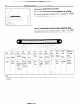
INTRODUCTION GENERAL - Geraeral 17 Data and Specifications DATA AND SPECIFICATIONS NOOHA-A OOW556 L042G Description Vehicle dimensions VNJ LFIH VRJLFIH TRSLF/H TNSLFIH mm (in.) Overall length Without spare tire 0 3,960 (155.9) 3,960 (155.9) 3,960 (155.9) 3,960 (155.9) With spare tire Overall width 0 0 3,995 (157.3) 1,680 (66.1) 3,995 (157.3) 1,680 (66.1) 3,995 (157.3) 1,680 (66.1) 3,995 (157.3) 1,680 (66.1) Overall height 0 1,840 (72.4) 1,840 (72.4) 1,850 (72.8) 1,850 (72.
INTRODUCTION L042G Description - General Data and Specifications VNJLFIH TNSLFIH VRJ L.F/H TRSLFIH 1 Engine Model G54B No. Type Number i In-line ‘4 of cylinders G54B G54B OHC In-line 4 G54B In-line OHC OHC 4 In-line OHC 4 Bore 91 .I mm (3.59 in.) 91 .I mm (3.59 in.) 91 ,I mm (3.59 in.) 91 .I mm (3.59 in.) Stroke 98.0 mm (3.86 in.) 98.0 mm (3.86 in.) 98.0 mm (3.86 in.) 98.0 mm (3.86 in.
INTRODUCTION Description m--__ L042G Data and General Specifications VRJLFIH VNJLFIH / Tightening Torque TNSLFIH 19 TRSLFIH Brakes We Power Front Disc Rear Drum (Leading steering Gear type Integral Gear ratio ball nut) 60 liters (15.9 U.S. gal./1 3.2 Imp. gal.) TIGHTENING TORQUE NOOJA- Description Head mark Head mark Nm Thread for general (size x pitch) mm 07 ft.lbs. ft.lbs. Nm 2.2-2.9 4.9-7.8 3.6-5.8 purposes I 6x 1.0 3.0-3.9 8x 1.25 7.9-I 5.8-8.7 13-19 9.
8-1 ELECTRICAL CONTENTS ACCESSORY ...................................................... 188 Cigarette Lighter ............................................ ,190 Clock ............................................................... ,191 AUDIO SYSTEM ................................................ .192 AUTOMATIC FREE-WHEELING HUB INDICATOR SYSTEM ........................................ 208 Automatic Free-wheeling Hub Indicator Control Unit ..................................... ,216 Pulse Generator ........
8-2 ELECTRICAL ELECTRICAL SYSTEM PARTS LOCATION SYSTEM - Relay and Control Unit IPARTS LOCATION NOIBAB-A RELAY AND CONTROL UNIT Items -- Symbol D Air conditioner relay -Auto choke relay -Automatic free-wheeling G hub indicator control A unit 16W722 A n 17 A Condenser blower motor relay H Feed back carburetor control unit C Hazard warning flasher unit F Headlight washer relay F Heater relay E Intermittent wiper relay ~___ Light control relay ~___ Over drive relay F I F Power
ELECTRICAL FI)I -Headlight h” k\\\ washer SYSTEM PARTS LOCATION relay Hazard warnina f 1 STB Revision - Relay and Control Unit 8-3
8-4 ELECTRICAL SYSTEM PARTS LOCATION - Sensor SENSOR Symbol Items A Oxygen sensor Pulse generator B -- D Throttle position sensor _____ Vehicle-speed sensor C ~~ Water temperature E sensor ltw722 I Ileedometer 16W1506 p Revision Throttle position sensor.
ELECTRICAL SYSTEM PARTS LOCATION 8-5 - Diode DIODE Diode (for automatic transmission Diode (for EGR warning 1 @NJ22 STB Revision light) oil
ELECTRICAL SYSTEM PARTS LOCATION - Fusible Link and Fuse FUSIBLE LINK AND FUSE -Items Symbol Dedicated fuse (for air conditioner Dedicated fuse (for headlight circuit) 1 / STBI levision ‘I E A Multipurpose C fuse NOTE For detailed information concerning fuses, refer to the section regarding TION (P.8-69, 70.
ELECTRICAL SYSTEM PARTS LOCATION 8-7 -Grounding GROUNDING Headlight washer relay, h I 1 STB Revision !Ja _ .
8-8 ELECTRICAL \\/ / 16W1512 SYSTEM PARTS LOCATION -Grounding 1 5. STB Revision 1 :.
INSPECTION OF HARNESS CONNECTOR - Inspection of Harness 8-9 Connector INSPECTION OF HARNESS CONNECTOR CONTINUITY TOR AND VOLTAGE NOECAM TEST FOR CONNEC- Following procedures shall be followed for testing continuity and voltage at connector in order to prevent improper contact and deterioration of waterproof in connector. CONVENTIONAL (NON-WATERPROOF) CONNECTOR Check shall be done by inserting a probing needle from harness side. WATER PROOF CONNECTOR Caution.
8-10 INSPECTION OF HARNESS CONNECTOR - Inspection of Harness Connector (2) Insert harness of terminal to be rectified deep into connector from harness side and hold it there. (3) Insert tip of screwdriver [1.4 mm (.06 in.) width] into connector in a manner as shown in the figure, raise housing lance slightly with it and pull out harness. Housing lance NOTE Tool No. 753787-l of screwdriver.
INSPECTION OF HARNESS CONNECTOR RECTANGULAR (1) Disengage - Inspection WATERPROOF front of Harness Connector 8-71 CONNECTOR holder by using a screwdriver and remove it. (2) Insert tip of screwdriver [*0.8 mm (03 in.) width] into connector in a manner as shown in the figure, push it lightly to raise housing lancer and pull out harness. *If right size screwdriver is not available, convert a conventional driver to suit the size.
8-12 INSPECTION OF HARNESS CONNECTOR - Inspection of Harness Connector (3) Press contact point of male terminal down by holding a screwdriver Il.4 mm (.06 in.) width] in a manner as shown in the figure. Caution Correct lancer to be in proper inserted into connector.
WIRING HARNESS 8-13 - Troubleshooting WIRING HARNESS TROUBLESHOOTING NO8DAAA The most important point in troubleshooting is to determine “Probable Causes”. Once the probable causes are determined, parts to be checked can be limited to those associated with such probable causes. Therefore, unnecessary checks can be eliminated. The determination of the probable causes must be based on a theory and be supported by facts and must not be based on intuition only.
8-14 WIRING HARNESS - Troubleshooting INSPECTION 1. Visual and aural checks Check relay operation, blower motor rotation, light illumination, etc. visually or aurally. The flow of current is invisible but can be checked by the operation of the parts. I 2. Simple checks For example, if a headlight does not come on and a faulty fuse or poor grounding is suspected, replace the fuse with a new one or ground the light to the body by a jumper wire to determine which part is responsible for the problem.
WIRING HARNESS 3. 8-15 - Troubleshooting Jumper wire A jumper wire is used to close an open circuit. Never use one to connect a power supply directly to a load. 1660227 4. A voltmeter is used to measure the circuit voltage. Normally, the positive (red lead) probe is applied to the point of voltage measurement and the negative (black lead) probe to the body ground. Black lead wire Ground Voltmeter y 1680228 I 5. Ohmmeter An ohmmeter is used to.
8-16 WIRING HARNESS - Troubleshooting 2. CONNECTION SWITCH figure illustrates a complex switch. The switch plates indicated by solid lines move in the direction of the arrow when operated. The continuity between terminals at each position is as indicated in the table below. This OFF 1st stage 2nd stage 3rd stage 1 --_ 4th stage 1660230 NOTE M denotes continuity between terminals. 16W896 CHECKING Cover Coil 1.
WIRING Normal Deenergized close state INC) type Energized state I Current -flows Current does HARNESS 8-17 - Troubleshooting When a normal close type relay as illustrated here is checked, there should be continuity between terminals (1) and (2) and between terminals 3 and 4 when the relay is deenergized, and the continuity should be lost between terminals 3 and 4 when the battery voltage is applied to the terminals 1 and 2.
WIRING HARNESS - Troubleshooting CHECKING 1660236 CABLES AND WIRES 1. Check connections for looseness, rust and stains. 2. Check terminals and wires for corrosion by battery electrolyte, $tc. 3. Check terminals and wires for open circuit or impending open circuit. 4. Check wire insulation and coating for damage, cracks and degrading. 5. Check conductive parts of terminals for contact with other metallic parts (vehicle body and other parts). 6.
WIRING Power HARNESS supply Fuse block (remove fuse) Test light r’TJ Switch \ Illumination light - Troubleshooting 8-19 2. CHECKING SHORTCIRCUITS (1) Remove the blown fuse connect the test light to the disconnected terminal. The test light should not come on. (2) Connect a lead wire of the test light to the power side of the connector 0. The test light should not come on. (3) Connect a lead wire of the test light to the load side of the connector 0.
8-20 WIRING HARNESS - How to Read Wiring Diagrams HOW TO READ WIRING DIAGRAM HOW TO READ CONFIGURATION NOEDBAE DIAGRAMS (1) Connector symbols A wiring diagram shows the installed condition of each connector in a schematic style. The connectors are shown and classified as follows, depending on their locations and are marked by connector symbols. In case connectors of the same shape (same number of wires) are centralized, their colors are indicated for identification. Examp’e : p.!- f.
WIRING HARNESS - HOW to Read Wiring Diagrams 8-21 (2) Identification of connectors differing according to different vehicle specifications Without wiring harness connectors, the inter-device or -wiring harness connectors which vary in shape or position on different vehicle specifications are given the specification-dependent connector identification svmbol (lower case alphabet) after a serial number.
8-22 WIRING HOW TO READ CIRCUIT The circuit diagrams HARNESS - How to Read Wiring Diagrams DIAGRAMS are functionally separated. (1) Indication of circuit connected to another circuit When the circuit in a circuit diagram connected to another circuit in a different diagram, the page number of that different diagram is indicated so that it can be referred to.
WIRING HARNESS - BO Read HOW Wiring 8-23 Diagrams (4) Indication of fuses, fusible links and centralized relays The fuses and fusible links in a circuit diagram are indicated by a wave symbol (-) and a double wave symbol (~1, respectively. At a centralized junction, the fuses are given fuse numbers and centralized relays are given connector symbols.
8-24 WIRING HARNESS - How to Read Wiring Diagrams (7) Indication of shielded cables A shielded cable used , for example, in an electronic control circuit for prevention of malfunctions that may otherwise be caused by radio interference is indicated by a solid line sandwiched between dashed lines ( E).
WIRING HARNESS - How to Read IDENTIFYING Position improper of guide to prevent connection 8-25 Diagrams CONNECTORS In circuit diagrams, the connectors are indicated by symbolic marks which show the number of their wires and whether they are male,or female connectors. (1) Number of connector wires The number of divisions in the connector diagram indicates the number of wires. A cross in a division, however, indicates the position of a guide to prevent improper connection.
8-26 WIRING SYMBOLIC Various HARNESS - HOW to Read Wiring Diagrams MARKS equipment is indicated Battery Body ground Fuse Equipment Fusible link Motor symbolically in circuit idiagrams as shown Single bulb Resistor Speaker Coil below. Capacitor Diode ground ~ Transistor 4 4 Crossing of lines with conron -1~ WIRE COLOR CODES Wire colors are identified by the following color codes. Example: 1.
WIRING OVERALL WIRING HARNESS DIAGRAM ) STB Revision - Overall Wiring Diagram 8-27 NOBDC-‘3
8-28 WIRING HARNESS - Engine Compartment 1 ENGINE COMPARTMENT Connector symbol A AA156 ;:::I Main fusible link ;:::I 4WD indicator switch A-05 Automatic transmission oil temperature switch A-06 Back-u light and 4WD indicator A-07)wiring f!arness and cord assembly combination ;:g> Back-up light switch A-l 0 OD-OFF solenoid A-l 1 Pulse generator A-l 2 Front wiring harness and transmission wiring harness combination A-13 Air conditioner solenoid valve A-l 4 Front wiper motor A-52 A-28 A-29 A-34 A
WIRINGA-06 ; ,.
8-30 WIRING HARNESS - Interior B-01 Be03 and Frame 2 INTERIOR AND FRAIVIE Connector symbol 1 B B-32 B-33 \ B-29 \ “-I2 B-05 \ 9 B-06 B-08 \ B-p7 \ B-p9 B-l 0 1 AB-26 B-27 B-22 STB Revision H-21 -1 36W617
WIRING HARNESS B-01 Dome light B-02 Door switch (R.H.) :::3 Rear speaker (R.H.) B-05 Defogger (-) B-06 Back door wiring harness and license plate light wiring harness combination B-07 Rear wiper motor B-08 Rear washer motor B-09 Defogger (+) B-l 0 Back door wiring harness and defogger cable (+) combination B-l 1 Rear side marker light (R.H.) B-12 Frame wiring harness and back door wiring harness B-13)combination B-14 Rear combination light (R.H.) &z}License plate light (R.H.
8-32 WIRING 3 INSTRUMENT Connector HARNESS - Instrument Panel PANEL c-04 symbol C-06 C C-65 C-64 C-63 C-61 CL57 C-b6 C!55 Remarks For information refer to P.8-7.
WIRING cy50 C149 Cl48 HARNESS - Instrument Panel c-47 El$,}Cigarette lightet C-43 Cigarette lighter illumination light E::$ Radio C-46 Shift position illumination light C-47 Inhibitor switch C-48 OD-OFF switch C-49 Parking brake switch C-50 Seat belt switch C-51 Hazard switch Column switch C-54 Key reminder switch C-55 Ignition switch C-56 Stop light switch E3 Ision C-57 Dimmer control switch C-58 Front wiring harness and door wiring harness (L.H.
8-34 WIRING MARNESS 1 STARTING CIRCUIT (VEHICLES WITH A MANUAL - Starting Circuit TRANSMISSION) Ignition switch TA RT Battery Main link @.
WIRING HARNESS (VEHICLES WITH AN AUTOMATIC Battery -p 8-35 Circuit TRANSMISSION) Sub fusible link (IGN . SW) A-23 Main fusible link - Starting Ignition switch lrril‘I 1.25-B -5-w A-02 U c-47 a 1 2-BY Ia- 1 2-BY 1 Inhibitor switch N 2-BY,2-BY*2 2-BY 2-BY*l P BYBY fTl 37W613 Remark For information concerning the ground refer to P.8-7. Wiring color code Br: Brown 8: Black LI: Light blue 0: Orange points (example: G: Green P: Pink ) STB Revision 0 ).
8-36 WIRING 2 IGNITION HARNESS - Ignition Circuit CIRCUIT A-23 Main fusible link Batterv / Sub fusible (IGN * SW) link Ignition switch IR I i r mw Distributor To combination meter (TACHO) [Refer to P.8-52.1 J A-44 37W609 Remark For information refer to P.8-7.
WIRING 3 CHARGING HARNESS - Charging 8-37 Circuit CIRCUIT Ignition switch .n S‘ Main fusible link Battery I 3 cl m’ L A-02 Sub fusible link (IGN - SW) A-23 , ‘I81 m 3 3 c: -22 3 c!J t El A-48 Alternator I To turn signal flasher unit [Refer to P.8-49.1 1 Comornatron Remark For information refer to P.8-7. concerning Wiring color code B: Black LI: Light blue the ground Br: Brown 0: Orange .
8-38 WIRING HARNESS - 4 FEED BACK CARBURETOR Battery Main fusible link Feed Back Carburetor Circuit CIRCUIT m’ A-02 efl EEI j i -1.25-B- Sub fusible L W link Ignition BW switch uA-2i I I: h W a r A-28 zix--I c: qi To alternator [Refer to P.8.37.1 1 -26c-1 ziE2 I BW ". r Feed back solenoid valve YG 1.25-BW"' Slow cut solenoid valve YL 1.
WIRING HARNESS - Feed Back Carburetor 8-39 Circuit Ignition coil ) _ ,E3 $-To q A-42 A-4 vacuum solenoid valve [Refer to P.8-57.1 7 BR cl c-2 ‘Af r , I I I I I I ; : ; : 0.85-BW YG YL. I RW, II II (I A-4 A-9 A-3 A-6 A-5 B-l 1 B-6 B-9 B-IO I I I- - - - -. -_ __ __ L---__._.
8-40 WIRING HARNESS - Layout of Components WC) LAYOUT OFCOMPONENJS [FBC) CD II A \\ 5FU131 Items Items Symbol Auto choke relay J Slow-cut solenoid valve Engine speed sensor (Ignition coil 0) G Feed back carburetor control unit K Throttle opener control solenoid valve (for the air-conditioner) Feed back solenoid valve I C Throttle Oxygen sensor I H Vacuum switch Secondary I I Throttle solenoid air control solenoid valve opener valve contr Symbol position sensor 1 Wat
WIRING sensor U’S) / control HARNESS - Layout 5FUl unit w1515 1/ LTBI levision of Components (FBC) 8-41
8-42 WIRING 5 OVERDRIVE HARNESS CONTROL - Overdrive Control System Circuit SYSTEM CIRCUIT / Sub fusible link Ignition $in switch fusible a I To combination meter [Refer to P.8-52.1 ~ To alternator [Refer to P.8-37.1 ~ 0.85-W To column [Refer to ~ 0.85-RL switch P.8-51.1 1 0.85-W i Remarks (I) For information concerning the ground points (example: 0). refer to P.8-7. (2) The symbols 0, 0, etc.
WIRING HARNESS - Overdrive Control System 8-43 Circuit *I Inhibitor Water temperature switch 1 I OD-OFF relav r C--63 RL ) To back-up light [Refer to P.8-45.1 2-BY 9 3 4 5 To starter relay [Refer to P.8-34, 35.
8-44 WIRING HARNESS Tail Light. Position Light, Rear Side Marker Light, License Plate Light and Back-Up Light Circuit - 6 TAIL LIGHT, POSITION LIGHT, REAR SIDE MARKER LIGHT, LICENSE PLATE LIGHT AND BACK-UP LIGHT CIRCUIT ?I w19 eF=7 I 1 1 I nwr II Battery Sub EiT n1.
WIRING HARNESS - Tail Light, Position License Plate Light Light, Rear and Back-Up Side Marker Light. Light Circuit 8-45 fl!FEEl Column I switch Lighting switch Light control relay F-GW -GW B-l 2 B-l 1 Tail light Tail light Back-up light Rear $ combination light (R.H.) RG RI.G ‘El3 Tail light Tail light Back-up light I Remarks (1) The broken lines are applicable to models equipped wrtn an automatic transmission. (2) For information concerning the ground points (example: 0 ). refer to P.
8-46 WIRING HARNESS - Headlight Circuit 1 7 HEADLIGHT CIRCUIT M-!l Battery -1.25-B1 Main link il IRI viI!YR I‘i Sub fusible link A-02 5-w 5-w m5-w M 0.5-G 2-R U A-23 fusible F 2-B 71' 0 [ES $$J A-33 Dedicated 1 c-05 fuse 1 BEAM 1 ('R; J Combination meter “I w C-52 -32 A-34 Light relay control Lighting switch Dimmer switch Column‘ Remark For information concerning the ground POintS (example: 0 ), refer to P.8-7.
WIRING HARNESS - Dome 8-47 Circuit Light 8 DOME LIGHT CIRCUIT A-02 Battery r 1.25-B \ 3 Main fusible Sub 5-w rl5-w u 2-w m fusible link 0.5-G 2-R A-23 link To column [Refer to Multi-purpose fuse switch P.8-46.1 1.25-GB 2-R & m At Combination meter 1.25-GB To hazard flasher unit [Refer to P.8.49.1 I-- C-27’ B-01 Dome light (L.H.) (R.H.) Door switch 37W620 Remark For information refer to P.8-7.
8-48 WIRING HARNESS 9 TURN-SIGNAL AND A-02 - a3 1.25-B- Main fusible Hazard Light Circuit LIGHT CIRCUIT Sub fusible 1 link 0.5-G A-23 5-W l-l (5-W 8 Turn-Signaland HAZARD 1 m Battery r - 1 81 El3 Ignition 2-R switch 2-W link A-32 GW To lighting switch e [Refer to P.8-46.1 * 2-R 2-RW I- 2-B To column switch [Rear to P.8-461 I t 'I 7 l.ZS-tit3 - 0.85-GY +a I_ \ (Bl -6 0.
WIRING HARNESS - Turn-Signal OR 0 RI. Turn-signal Turn-signal flasher unit I I switch and Hazard GO 0 0.3 iazard Hazard flasher unit r E L: ci Light 8-49 Circuit switch “1 *2 1 C-62 C Turn-signal and hazard -> & light Rear Combination light (R.H.) light Rear combination light (L.H.) mm c-57 Dimmer switch control OL Em B WL (1) For information concerning the ground points (exam“em~:~s~ ) refer to P.8-7. (2) The symbols 0, 0, etc.
8-50 WIRING HARNESS - Stop Light Circuit IO STOP LIGHT CIRCUIT 1 In3 Sub fusible link A-07 Main link fusible Multi-purpose fuse 0.85-GR 0.85-G c-51 0.85-G Hazard switch 1.85-WG $R WL 1 1 1 ’ ,I ,I ( Turnsignal switch Rear light Remark For information refer to P.8-7. concerning Wiring color code B: Black LI: Light blue the Br: Brown 0: Orange ground points (example: G: Green P: Pink 1 STB Revision 0 cdmbination (L.H.) Rear light c:mbination (R.H.
WIRING HARNESS 11 INSTRUMENT - Instrument Panel Wumination PANEL ILLUMINATION Battery CIRCUIT Sub fusible 5-w Main fusible 5-w l-75-W LA-23 m 8-51 Circuit link 0.5-G 2-R link @L CA M’ A A-22 rx c-l Y$lO I Optical fiber I Multi-purpose fuse control illumination 0 3 a .
WIRING HARNESS - Meter Circuit 12 METER CIRCUIT 1 m A-02 Sub fusible link Ignition switch 15-w Main link fusible - -- \ A-22 ‘1 m -ffiFirmer control [Refer to P.8-511 I 0 column : [Refer to P.E BY 4 @/ Multi-purpose fuse I To turn,signal switchfd,,, (bYI , [Refer to P.8-491 1 To seat belt timer [Refer to P.8-661 G 1 To seat belt warning buzzer [Refer to P.8-661 M I To alternator 0.85tW fRefer to P.
WIRING HAFNESS - Meter 8-53 Circuit O&y-ssure [Eal > El Oil pressure gauge unit YRB BRYR ElxQ A-20 I.+ A-03 A-06 4WD indicator ’ -- .- I I I E 1 ,’ I I * - -,,- - - - - -- YB L, I 4 Brake fluid level sensor 0.85-B T -I m-w I I k-1 A-04 A-07 rA fs I Ei switch Jo cigarette lighter [Refer to P.
8-54 HARNESS WIRING - Horn Circuit 13 HORN CIRCUIT /I 1 m Battery Sub fusible A-23 1 m 0.5-G 5-w/-75-w 3 Main fusible u link Ignition switch Z-W link OFF ]AM ACC] Multi-purpose fuse a -i :: C , To wiper motor [Refer to P.8-59.1 A-3 Column A-39 switch 37W608 Remark For information concerning the ground refer to P.8-7. Wiring color code Br: Brown B: Black LI: Light blue 0: Orange points (example: G: Green P: Pink 1 STB Revision q ), GI.
WIRING HARNESS - Heater 8-55 Circuit 14 HEATER CIRCUIT *I BI l!zEl A’ lonition switch Battery 0 (Ignition switch) L Multi-purpose fuse To turn signal flasher [Refer to P.8-49.1 unit4 -P--- H M2 Ml bFF n [ 0.85-RL Blower motor !! C-18 M I Blower i \ Blower resistor switch motor T LBLI LRLW El3 I Heater relay 8L LRLR El *2 *1 37W614 Remark For information concerning refer to P.8-7.
8-56 WIRING HARNESS 15 AIR CONDITIONER - Air Conditioner Circuit CIRCUIT Ignition Main fusible I;..,, Sub fusible (Fuse B) m 1 switch link +2 0.85-R I I (lonition switch) I I ,!..I ’ ’ T unit ~ 0.85-RL To turn signal flasher [Refer to P.849.1 L I 3-LRwQ J I , ,0.85-LW To cigarette lighter [Refer to P.8-62.1 0.
WIRING HARNESS - Air Conditioner 8-57 Circuit B 0.3 LvfL ElFI Air conditioner relay @ ‘I I *2 H Air :on!$!er feed back carburetor ) to control unit 85-Bw:o.85-Bw 0 0: u A-25 (Bl rela [Refer to P.8-39.1 Lw 20.85-BWr ll 10.85-BWL& A-13 * Vacuum valve solenoid @,0.85-WB A-45 0.
8-58 WIRING HARNESS 16 WIPER AND WASHER - Wiper Circuit Washer LW 1 m CIRCUIT IL& Battery and Sub fusible Ignition link -1.25-BAs2 Main fusible switch 2-R 5-w r--(5-w Z-W link To lighting switch Light control relay Multi-purpose fuse @ I-2-B Intermittent wiper control relay r Remarks (1) For information concerning the ground points (example: q ). refer to P.8-7. (2) The symbols 0.0, etc.
WIRING HARNESS m -- - Wiper and Column switch FronthiDer switch Washer 8-59 Circuit -1 BP 118 B f!EEl Headlight washer switch I -_I Rear wiper and washer switch I 1 z-09 c-53 @4-zo-(YL) @JY' @- BR @- Lw -1 j A-14 I 1A-58 I Frontwasher motor Front wiper motor Rearwasher motor WB Q I.
S-60 WIRING HARNESS 17 RADIO/CASSETTE Battery A-02 _ / Cassette Deck Circuit DECK CIRCUIT L1 1 EQ3 1 lm Ignition Sub fusible 1.25-B A-23 \ rlin - Radio 5-*5-w link 0.5-G m 2-w fusible To light control relay [Refer to P.8-461 To air conditioner [Refer to P.8-561 To combination 4 meter [Refer to P.
WIRING HARNESS - Radio / Cassette 8-61 Deck Circuit (R.H.) Front speaker 1 (L.H.) Rear speaker 37W618 Remarks (1) For information concerning the ground points (example: 0 ), refer to P.8-7. (2) The symbols 0, 0, etc. indicate that the wiring is connected (using the same numerical symbol) to the facing page. (In other words, 0 on the right page is connected to 0 on the left page.
8-62 WIRING 18 CIGARETTE HARNESS - Cigarette Lighter / Clock Circuit LIGHTER / CLOCK CIRCUIT Sub fusible r-l E-f? Ignition link ‘) switch n -u yn;in fusible 7-R To light control [Refer to P.8-461 To radio [Refer to To hazard [Refer to flasher P.8-491 \*I relay GW P&601-, unit4 3FI .LJ- Pm G Multi-purpose II illumination fuse I light To heater illumination [Refer to control light P.8-511 Clock 1 J h 6 CT 0: Jc-36 To combination [Refer to P.
WIRING 19 DEFOGGER HARNESS - Defogger CIRCUIT Sub fusible A-23 5-wn5-w ynlin 8-63 Circuit 0.5-G I I ml EEH link Ignition U fusible switch z-w , A 1 z I l% 7 N (#IO -22 u To light control ~-RN w relay [Refer to P.8-461 +!I00 Defogger 1.25-B m I Ki . 4 m 1.25-BR / B-05 / B Q z A pFJ Bg L-l 2-FB m Multi-purpose @fuse D 3-B U B-13 BR Q i m of A To column switch [Refer to P.8-461 LY!ii!T Rheostat x7. Remarks For information refer to P.8-7.
8-64 WIRING 20 POWER WINDOW HARNESS, - Power Window Circuit CIRCUIT w EEH Ignition - .. I 81 switch II 1 1.25-B Main link fusible Multipurpose fuse [Refor to P.8-491 , I- (RL) 2-LR bg Power window main switch I I -I *1 1.25-R *2 1.25-G Remarks (I) For information concerning the ground points (example:m). refer to P.8-7. (2) The symbols 0, 0, etc. indicate that the wiring is connected (using the same numerical symbol) to-the facing page.
WIRING R B0 Power motor window (L.H.) bM B-31 c :: r HARNESS - Power 2-B F , r > .I. -I Window - 8-65 Circuit To colunm switch [Refer to P.8-511 washer relay [Refer to P.8-581 Power window relay IRL) :=2-L, 04 2-L g: 2-B 2-RL Power window sub switch (R.H.) 1.25-R @*1.
8-66 WIRING HARNESS - Buzzer Circuit 21 BUZZER CIRCUIT nil1 Battery -1.25-B A-02 Sub fusible - ‘I 01 IT8 link Ignition switch 0 Main link fusible dhm b- Multi-purpose OR Key reminder A0 switch [Refer to P.8-491 1 0 c-03 r C -CCl z-CY z- a m c-50 3 P-P P mm-l aa-cd -.A IC -J ski&t switch I.5 ‘bb’ Key reminder and seat belt warning buzzer Combination meter Seat belt warning timer Remark For information refer to P.8-7.
WIRING HARNESS - Automatic Free-Wheeling FREE-WHEELING Battery n -5-w Main link Indicator System HUB INDICATOR Sub 171. Hub fusible Circuit B-67 SYSTFM link 1 m2-G m fusible rgntrron Iz-w - _I swrtcn ON I Pulse generator Multi-purpose fuse To column [Refer to e switch P.8-461 z 1 :: m C 0: 1 I I 0 2I ’ - I++m c-07 1 Vehicle speed detective circuit Pulse detective circuit I EleAtrir circuit power d&V+ - LR 1 m m ,:cAcJl !!I T-r- m q OE! - z- C-06 -.
WIRING HARNESS - Back Door Lock Circuit 23 BACK DOOR LOCK CIRCUIT Battery Sub fusible _ $’ 5 link Multi-purpose fuse m ’ ) 1.25F-G A -1.25-G 1.25F-R 2-LR -To 0 1.25-R 2-B B-l 2 cza I I xx. . 77 B-24 [ cLL3 ALA CVN . . 77 m -To heater relay [Refer to P.8-551 column switch [Refer to P.8-511 0 I Back door lock actuator Wiring color code B: Black Br: Brown LI: Light blue 0: Orange Remark For information refer to P.8-7.
WIRING HARNESS - Centralized 896! Junction CENTRALIZED JUNCTION Main Fusible Link Circuit Cable color mm’ (ir?.) continuous Fusing current Sub Fusible current A 40 A 190 Link Circuit Cable color Fusible link size mm7 (in.2) continuous Fusing current Dedicated Feed back carburetor control circuit 1.25 (.
WIRING Multi-purpose Power - Centralized Junction Fuse supply circuit Battery Headlight HARNESS relay Ignition switch (IG) Battery Ignition switch (ACC) Fuse No.
CHARGING CHARGING SYSTEM - General 8-71 Information SYSTEM GENERAL INFORMATION NOBEMD The charging system comprises battery, alternator with regulator, charging indicator light and wire. The alternator has 6 built in rectifiers (3 positive and 3 negative), which rectify alternating current to direct current. Accordingly, the alternator terminal B is D/C. Furthermore the alternator regulates the charge voltage through the use of battery voltage detection system.
8-72 CHARGING SYSTEM - General Information MAINTENANCE Test indicator FREE TYPE BATTERY The maintenace-free battery is, as the name implies, totally maintenance free and has no removable battery cell caps. Water never needs to be added to the maintenace-free battery. The battery is completely sealed, except for small vent holes in the cover, These vent holes allow what small amount of gasses are produced in the battery to escape.
CHARGING SYSTEM -Specifications SPECIFICATIONS GENERAL SPECIFICATIONS ALTERNATOR NOOEB-B Specifications ~-Battery voltage sensing Items Type Model No. A2T03477 Part No. MD1 10318 Rated output 12150 VIA Voltage regulator Electronic built-in type BAlTERY Specifications Items Type Ampere hours (5 HR) Ah 55824R (S)-MF 1 36 Cranking rating [at - 178°C (O”F)] min. Reserve capacity A 420 75 NOTES 1.
8-74 CHARGING SYSTEM -Specifications TORQUE SPECIFICATIONS items __- Nm ft.lbs. 9-l 1 Alternator brace bolt 12-15 Alternator support bolt nut 20-22 14-16 High pressure hose nut 20-25 14-18 Low pressure hose nut 30-35 22-25 .
CHARGING 8-75 SYSTEM -Troubleshooting TROUBLESHOOTING NOBEH- Symptom Probable cause Remedy Reference we Charging warning indicator does not light with ignition switch “ON” and engine off. Fuse blown Check fuses 8-70 Light burned out Replace light - loose Tighten loose connections - voltage regulator faulty Replace voltage regulator 8-79 Adjust tension or replace drive belt Refer to GROUPS.
8-76 CHARGING 3 CHARGING SYSTEM - Circuit Diagram CIRCUIT Ignition switch OFF IAM Main fusible link fl.3-Br Battery 3 A m’ L A-02 1~5~~ , Sub fusible (IGN . SW) A-23 IG ] c-55 3 m A link To turn signal flasher unit [Refer to P.8-49.1 Multin, Irnn4P ComSeter Remark For information refer to P.8-7.
CHARGING SYSTEM - Service Adjustment SERVICE ADJUSTMENT INSPECTION 8-77 Procedures OF THE CHARGING PROCEDUREswmAB SYSTEM VOLTAGE DROP TEST OF ALTERNATOR OUTPUT WIRE This test judges whether or not the wiring (including the fusible link) between the alternator B terminal and the battery (+) terminal is sound by the voltage drop method. Preparation (1) Turn the ignition switch to “OFF”. (2) Disconnect the battery ground cable.
8-78 CHARGING SYSTEM - Service Adiustment Procedures OUTPUT CURRENT TEST This test judges whether or not the alternator current that is equivalent to the nominal output. gives an output Preparation (1) Prior to the test, check the following items and correct as necessary. (a) Check the battery installed in the vehicle to ensure that it is in sound state*. The battery checking method is described in “BATTERY”.
CHARGING SYSTEM - Service Adjustment 8-79 Procedures Result (1) The ammeter reading must be higher than the limit value. If it is lower but the alternator output wire is normal, remove the alternator from the vehicle and check it. Limit value : 31 A min. Caution 1. The nominal output current value is shown on the nameplate affixed to the alternator body. 2. The output current value changes with the electrical load and the temperature of the alternator itself.
8-80 CHARGING SYSTEM - Service Adjustment Procedures e Ignition switch Load Alternator Ammeter Voltmeter I @ lid-hi! 6EK52 (5) Disconnect the alternator output wire from the alternator “B” terminal. (6) Connect a DC ammeter (0 to 100 A) in series between the “B” terminal and the disconnected output wire. Connect the (+I lead of the ammeter to the “B” terminal and connect the (-1 lead wire to the disconnected output wire. (7) Set the engine tachometer and connect the battery ground cable.
CHARGING SYSTEM - Service Adjustment Procedures 8-81 (2) Upon completion of the test, set the engine speed at idle and turn off the ignition switch. (3) Disconnect the battery ground cable. (4) Remove the test voltmeter and ammeter and the engine tachometer. (5) Connect the alternator output wire to the alternator “B” terminal. (6) Connect the battery ground cable.
8-82 CHARGING SYSTEM - Service BATTERY Adjustment Procedures CHARGING NOEEICDZ Caution When batteries are being charged, an explosive gas forms beneath the cover of each cell. Do not smoke near batteries on charge or which have recently been charged. Do not break live circuits at the terminals of the batteries on charge. A spark will occur where the live circuit is broken. Keep all open flames away from the battery. Battery electrolyte temperature may temporarily be allowed to rise to 55°C (131°F).
CHARGING SYSWVI - Alternator 8-83 ALTERNATOR REMOVAL AND INSTALLATION (Vehicles without Air Conditioner) NOEEJAE 0 Adjustment of the Drive Belt Tenslon (Refer to GROUP 7 COOLINGService Adjustment Procedures) Removal I)+ steps 1. Connection of alternator connector 2. Alternator 3. Shim 4. Support bolt 5. Brace NOTE (I) Reverse (2) l * the removal : Refer to “Service 9-11
8-84 CHARGING REMOVAL AND INSTALLATION SYSTEM (Vehicles with - Alternator Air Conditioner) 30-35 D Draining of Refrigerant CONDITIONING (Refer to - Service Adjust- ‘ost-installation Operation 1 Charging of Refrigerant (Refer to GROUP 24 HEATERS AND AIR CONDITIONING - Service Adjustment Procedures) D Adjustment of Drive Belt Tension (Refer to GROUP 7 COOLING and GROUP 24 HEATERS AND AIR CONDITIONING ~ Service Adjustment Procedures) :emoval ~~ Nm 1 20-22 14-16 Nm ft.lbs.
CHARGING SYSTEM SERVICE 6. - Alternator POINTS INSTALLATION 8-85 OF INSTALLATION OF ALTERNATOR (1) Position the alternator and insert the support bolt. (Do not attach the nut.) (2) Push the alternator forward and determine how many spacers [thickness: 0.198 mm (.0078 in.)] should be inserted between the front leg of the alternator and the front case (space A in the illustration). (There should be enough spacers so that they do not fall out when you let go of them.
CHARGING SYSTEM-Alternator 8 ? 10 \I 11 14 I 1 EL666 Disassembly 4* 1. 2. l a 3. 4. 5. 6. 4* 7. 8. 9. 10. 4* 11. 12. 13. 14. 4, steps Pulley Seal Rotor assembly Rear bearing Bearing retainer Front bearing Front bracket Stator Terminal Plate Regulator and brush holder Brush Brush spring Slinger 15. Rectifier assembly 16. Rear bracket NOTE (1) Reverse the disassembly (2) +e : Refer to “Service (3) l + : Refer to “Service 1 STB Revision procedures to reassemble. Points of Disassembly”.
CHARGING 8-87 SYSTEM-Alternator SERVICE POINTS OF DISASSEMBLY 7. REMOVAL OF FRONT BRACKET/lG. (1) Insert plain screwdriver core and pry downward. between Caution Do not insert screwdriver of damage to stator coil. REAR BRACKET front bracket and stator too deep, as there is danger (2) Rear cover may be hard to remove because a ring is used to lock outer race of rear bearing. To facilitate removal of rear cover, heat just bearing box section with a 200-W soledering iron.
8-88 CHARGING l SYSTEM-Alternator Check rotor coil for grounding. Check to ensure that there is no continuity between slip ring and core. If there is continuity, replace rotor assembly. 6EL115 STATOR Make continuity test on stator coil. Check to ensure that there is continuity between coil leads. If there is no continuity, replace stator assembly. l 3ELOlO l Check coil for grounding. Check to ensure that there is no continuity between coil and core. If there is continuity, replace stator assembly.
8-89 CHARGING SYSPE l Diode trio test Check three diodes for continuity by connecting a circuit tester to both ends of each diode. If there is no continuity or no continuity in both directions, diode is defective and heatsink assembly must be replaced. lELll2 REPLACEMENT OF BRUSH A brush worn away to the limit below. is replaced using the procedure , (1) Remove spring. the pigtail solder and take out the old brush and (2) Install brush spring and new brush in brush holder.
8-90 CHARGING SYSTEM-Alternator SERVICE POINTS OF REASSEMBLY 3. REASSEMBLY OF ROTOR ASSEMBLY Perform reassembly in reverse procedure of disassembly, Before rotor is attached to rear bracket, insert wire through small hole made in rear bracket to lift brush. After rotor has 6een installed, remove the wire.
STARTING SYSTEM-General STARTING SYSTEM GENERAL INFORMATION Information 8-91 NOBFAAJ The electrical circuit of the starter system consists of battery, starter motor, solenoid switch, ignition switch, inhibitor switch, connecting wire and battery cable. In the starter system and electrical circuit, electricity flows to activate the coils of the starter motor solenoid when the ignition switch is turned to the start position.
8-92 STARTING “S” “6” terminal SYSTEM - General terminal \ Sole;oid Information coil - clutch Brush gear 1 ST6 Revision type reduction
STARTING 8-93 SYSTEM - Specifications SPECIFICATIONS GENERAL SPECIFICATIONS NOIFB- Items Specifications Starter motor Reduction Type Model No. MIT70481 Part No. Rated output drive M DO99667 kW1 v I.2112 No. of pinion teeth 8 SERVICE SPECIFICATIONS Items Standard Specifications values Starter motor Free running characteristics Terminal voltage V 11 Current A Max. 90 Speed r.p.m Min. 3000 0.5-0.8(.020-,031) mm (in.) Under-cut depth Commutator diameter mm (in.
8-94 STARTING SYSTEM -Troubleshooting TROUBLESHOOTING NOFH- Remedy Reference paw Check battery specific gravity Charge or replace battery 8-81 8-82 Repair or replace cables 8-81 Adjust or replace switch Refer to GROUP 21.
STARTING 1 STARTING (VEHICLES SYSTEM CIRCUIT WITH A MANUAL - Circuit 8-95 Diagram TRANSMISSION) Ignition switch Ik \ OFF \ START ON 9 w 11171 $in ACC c-55 ST fusible .
8-96 STARTING SYSTEM - Circuit Diagram (VEHICLES WITH AN AUTOMATIC TRANSMISSION) I Sub (IGN A-23 _ 5-WI-754 L-l m fusible . SW) 1 0.5-G link Ignition switch 1, 1, 1L-W Battery c-47 2-BY-Z-BY*2 !-BY N Z-BY1 L-l (Z-BY*] P BYBY R “I Remark For information refer to P.8-7.
STARTING WSTEM - Starter Motor 8-97 STARTER MOTOR REMOVAL AND INSTALLATION 16-19 12-l? 12-14 NOBFJAE Nm ft.lbs. 15W1564 Removal steps 1. Air filter 2. Connection of starter l * 3. Starter motor NOTE (1) Reverse the removal procedures (2) ++ : Refer to “Service Points motor connector to reinstall. of Installation” INSPECTION PINION GAP ADJUSTMENT I, Disconnect field coil wire from “M” -terminal of magnetic switch. 2. Connect a 12V battery between “S” -terminal and “M” terminal. 3.
8-98 STARTING SYSTEM -Starter Motor 4. Check pinion to stopper gauge. Standard Pinion value : 0.5-2.0 clearance (pinion gap) with a feeler mm (.020-.079 in.) 6EL003 5. If pinion gap is out of specification, adjust by adding or removing gaskets between magnetic switch and front bracket. lEL113 PULL-IN TEST OF MAGNETIC SWITCH 1. Disconnect field coil wire from M-terminal of magnetic switch. 2. Connect a 12V battery between S-terminal and M-terminal. / Field 3.
WEEM -Starter I- Carbon-pile rheostat 6EL07’ 8-99 Motor FREE RUNNING TEST 1. Place starter motor in a vise equipped with soft jaws and connect a fully-charged 12-volt battery to starter motor as follows : 2. Connect a test ammeter (loo-ampere scale) and carbon pile rheostat in series with battery positive post and starter motor terminal. 3. Connect a voltmeter (16volt scale) across starter motor. 4. Rotate carbon pile to full-resistance position. 5.
STARTING SYSTEM -Starter DISASSEMBLY Disassembly +* 4* +* +* Motor AND REASSEMBLY steps 1. Screw 2. Magnetic switch 3. Screw 4. Screw 5. Rear bracket 6. Brush holder 7. Brush 8. Rear bearing 9. Armature 10. Yoke assembly 11. Ball 12. Packing A 13. Packing B 14. Plate 15. Planetary gear 16. Lever l d 17. Snap ring l a 18. Stop ring 19. Over running clutch 20. -Internal gear 21. Planetary gear holder 22. Front bracket 6ELlSS NOTE (1) Reverse the disassembly procedures to reassemble.
STARTING SYSTEM-Starter 8-101 Motor SERVICE POINTS OF DISASSEMBLY 9. CAUTION OF ARMATURE/ll. BALL When removing the armature, do not lose the ball which acts as a bearing for the armature and tip. 17. DISASSEMBLY OF SNAP RING/18. STOP RING (1) Push the stop ring towards the snap ring using the proper socket. (2) After removal of the snap ring with the snap ring pliers, remove the stop ring and the over-running clutch.
8-102 STARTING SYSTEM-Starter Motor (2) Check the outer diameter. Standard value : 29.4 mm (1.157 in.) Limit : 28.8 mm (1.134 in.) lEL116 (3) Check the depth of the undercut Standard value : 0.5-0.8 between mm (.020-.031 segments. in.) lEL66 BRUSH HOLDER Check conductivity between the brush holder holder. If there is no conductivity this is normal. Brush plate and brush holder OVERRUNNING CLUTCH 1. While holding clutch housing, rotate the pinion.
STARTING SYSTEM -Starter 8-103 REPLACEMENT OF BRUSHES AND SPRINGS 1. Brushes that are worn beyond limit line, or are oil-soaked, should be replaced. 2. When replacing field coil brushes, crush worn brush with pliers, taking care not to damage pigtail. i&l E -Limit Motor line 1ELOlI New brush Soidered (Make sure that there is no excess solder on brush surface) 3. Sand 4. Insert Make brush 5. When holder pigtail end with sandpaper pigtail into hole provided sure that pigtail and excess surface.
8-104 STARTING SYSTEM-Starter Motor SERVICE POINTS OF REASSEMBLY 18. REASSEMBLY OF STOP RINGi17. SNAP RING Using a suitable pulling tool, pull overrunning clutch stop ring over snap ring.
IGNITION SYSTEM -General Information 8-105 IGNITION SYSTEM GENERAL INFORMATION NOUGAAB The ignition system consists of battery, distributor, ignition switch and connecting wire.
IGNITION SYSTEM-General Information IISTRIBUTOR Vacuum controller lEL153 IGNITER OPERATION (1) When the signal rotor revolves a projection inside the signal rotor alternately moves away from and faces towards the core detector inside the igniter. (2) When the projection is separated from the core, an oscillating electrical circuit begins to oscillate, and when it faces, magnetic flux issuing from the core moves across the inside of the signal rotor, so when loss increases, oscillation ceases.
IGNITION 8-107 SYSTEM - Specifications SPECIFICATIONS GENERAL SPECIFICATIONS DISTRIBUTOR N08GB.B Items California Federal pointless Contact pointless T3T61980A Part No. Igniter MD109013 Built-in type Built-in type Firing order 1-3-4-2 1-3-4-2 IGNITION type Contact Type Model No. MD1 10264 COIL Specifications Items Type Model No. Oil filled Part No. M DO73079 SPARK type T3T65571 E-089 PLUG Model No.
8408 IGNITION SYSTEM - Specifications SERVICE SPECIFICATIONS N08GC-B Specifications Items Basic ignition timing at curb idle speed 7”BTDC Distributor Federal Governor Initial (crank deghpm) O/l 600 1 9/2800 Middle Final 1g/6000 Vacuum (crank deg/mmHg) Initial O/80 Middle 12/I 50 231280 Final California Governor (crank deghpm) initial O/l 600 Middle 912800 Final 1g/6000 Vacuum (crank deg/mmHg) Initial O/80 Middle 8/l 50 Final 201360 Idle advance (crank deg/mmHg) Initial O/60 F
IGNITLON 8-109 SYSTEM -Troubleshooting TROUBLESHOOTING NOBGH-- Symptom Probable cause Engine will not start or hard to start (cranks OKI Incorrect ignition Ignition coil faulty Inspect ignition Ignition faulty Inspect igniter 8-120 Inspect distributor 8-120 Inspect cord high tension 8-116 Replace plugs 8-115 Inspect wiring Spark plugs faulty Replace plugs Ignition Inspect wiring Adjust ignition Distributor Remedy timing Adjust faulty High tension cord faulty Spar
8-110 IGNITION 2 IGNITDN SYSTEM - Circuit Diagram CIRCUIT Sub fusible (IGN - SW) A-23 5-wn5-wu 0.5-G link Ignition switch 1 Z-W 63-I IAT 1 Main fusible link Rnttprv I 64-b ze cj _-’ m 3m A:“p N I CL I I m I Ei I L Disi To combination meter (TACHO) [Refer to P.8-52.1 d A-an b I Ignition I coil 37 w009 Remaik -‘For information refer to P.8-7.
IGNITION SYSTEM - Service Adjustment SERVICE ADJUSTMENT CHECKING IGNITION IGNITION TIMING 8-111 Procedures PROCEDURES TIMING NOEGIBA ADJUSTMENT Adjustment conditions: Coolant temperature: 80-90°C (170-I Lights and all accessories: Off Transmission: N (Neutral) 90°F) 1. Connect tachometer and timing light. 2. Start eng.ine and run at curb idle speed. I Curb idle speed rpm First 500 km (300 mile) 725';;; After 500 km (300 mile) 800 ?I00 3. 4.
8-112 IGNITION SYSTEM - Service Adjustment CHECKING NEGATIVE Procedures PRESSURE ADVANCE EQUIPMENT 1. Set the timing light. 2. Start the engine and allow it to idle. 3. Pull out the vacuum hose from vacuum controller and attach vacuum pump to nipple. 4. Check the advance while slowly applying negative pressure to the vacuum pump. If the advance is smooth when accompanying the increase in negative pressure, this is normal.
IGNITION SYSTEM-Service Adjustment SPARK TEST - ENGINE Procedures CANNOT 8-113 BE CRANKED If spark test is performed by cranking while the catalyst is hot, unburned gas will be supplied to the catalyst, and this is not desirable to the catalyst. For this reason, use the following methods which allow spark test to be performed without cranking. 1. 2. Remove the distributor cap. Check signal rotor position in relation to the pick-up.
8-114 IGNITION IGNITION SYSTEM - Ignition System SYSTEM REMOVAL AND INSTALLATION NOEGJAE 20-30 Spark +e ~~ +e *e plug l + ~~ e+ e+ removal 1. 2. 3. 4. 5. Distributor ~~ l + +* de l q Ignition Spark Spark Spark Spark Spark steps plug plug plug plug plug removal cable cable cable cable No. No. No. No. removal 1 2 3 4 16W1563 steps 1-4. Spark plug cables 6. Connection of distributor 7. High tension cable 8. Connection of vacuum 9. Distributor coil Nm connector hose steps 7.
IGNITION - Ignition 8-115 Svstem SERVICE POINTS OF REMOVAL No good Good SYSTEM l-4. CAUTION CABLE OF SPARK PLUG CABLES17. The cable is to be pulled out by grasping 721017 HIGH TENSION the cap part. 72T06t 9. 16W947 REMOVAL OF DISTRIBUTOR Before removing the distributor, position the piston in No. 1 cylinder at the top dead center on compression stroke by the following procedure. (1) Remove the cap from the distributor.
8-116 IGNITION SYSTEM-Ignition System 4. Clean with plug cleaner. Sand which has accumulated in the screw thread of the plugs is blown out by compressed air. 5. Using the plug gap gauge, check whether is normal, and if not, adjust it. Plug cleaner OlUOO89 NIPPON Plug gap gauge termine direction Standard rl CHECKING value SPARK : 1.0-1.1 PLUG the plug gap reading mm (.039-.043 in.) CABLE (1) Check that there are no cracks in the cap or in the insulating coating.
IGNITION SYSTEM-Ignition SERVICE 9. POINTS INSTALLATION 8417 System OF INSTALLATION OF DISTRIBUTOR (1) Align the notch on the crankshaft pulley with the timing mark “T” on the timing indicator to set the engine so that the No. 1 cylinder is at the compression top dead center. Notch on crankshaft pulley (2) Align mating mark on distributor on distributor driven gear.
8-118 SPARK IGNITION PLUG CABLE SYSTEM - Ignition System INSTALLATION I(1 3 -4 -3 -1 -2 3 I 3 2 4 View P 5EL04 / STB Revision 1
IGNITION SYSTEM 8-119 - Distributor DISTRIBUTOR DISASSEMBLY Disassembly AND REASSEMBLY steps 1. Breather 2. Distributor cap 3. Packing 4. Contact carbon 5. Rotor 6. Vacuum control 7. Ground wire 8. Lead wire l + Adjustment of air gap 9. Igniter 10. Rotor shaft 4* +*** 11. Signal rotor l * 12. Breaker plate 13. Spring retainer 4* 4* 14. Governor spring 15. Governor weight 16. Lock pin 4**+ 17. Driven gear 18. Washer 19. “0” ring 20. Distributor shaft 21. Washer 22. Oil seal 23.
8-120 IGNITION SYSTEM - Distributor SERVICE POINTS OF DISASSEMBLY 10. DISASSEMBLY OF ROTOR SHAFT/l 1. SIGNAL ROTOR Place igniter base on soft base (wooden block) and lightly tap rotor shaft to remove it from signal rotor. 13. DISASSEMBLY SPRING OF SPRING RETAINERI14. GOVERNOR Remove two spring retainers with pliers and then remove two governor springs. 6ELO6i ti II 17. DISASSEMBLY Pin punch OF DRIVEN GEAR (1) Mark location of driven gear on distributor shaft.
IGNITION 8-121 SYSTEM-Distributor 17. REASSEMBLY Install driven location. Distributor \ w OF DRIVEN GEAR gear into distributor shaft at previously marked 6EL093 12. REASSEMBLY /” A OF BREAKER PLATE Install igniter base to housing. Position the igniter base so that the projection (A) fits into the groove (9). I -1-- 11. REASSEMBLY OF SIGNAL ROTOR Install signal rotor to rotor shaft. Position the signal rotor so that the dowel pin fits into the groove. Socket .
8-122 IGNITION IGNITION REMOVAL Removal SYSTEM - Ugnition Switch SWITCH AND INSTALLATION NOEGLAE steps 16W1557 1. Lower column cover 2. Upper column cover 3. Cable band 4. Ignition switch 5. Key remaind switch NOTE Reverse the removal procedures to reinstall INSPECTION (1) Disconnect the wiring connector from the ignition switch, an ohmmeter to the switch side connector. (2) Operate the switch, and check the continuity between the terminals.
8-123 METERS AND GAUGES-Specifications METERS AND GAUGES SPECIFICATIONS GENERAL METERS SPECIFICATIONS AND GAUGES NOEHB- Specifications Items Speedometer Electromagnetic Type Tachometer Type Detection type Pulse type Ignition coil source Fuel gauge Type Fuel gauge unit Bimetal type (constant-voltage Type Water temperature Variable resistance Type Oil pressure type Bimetal type (7V operation) gauge unit Thermistor type gauge Bimetal type gauge unit Bimetal type Type Inclinometer Type Damp
8-124 METERS AND GAUGES - Specifications BUZZER Specifications Items Range of voltage used V IO-16 While buzzing (Terminal voltage at 13 V) Sound pressure Fundamental dB frequency 53-7 goo* 150 Hz SERVICE SPECIFICATIONS Specifications Items Standard values Speedometer indication error Meter with “km/h” indication km/h f4 -1 +4 0 +5 0 +5.5 +0.5 20 km/h 40 km/h 80 km/h 120 km/h Meter with “mph” indication mph +- 1.5 10 mph 25 mph + 1.5 50 mph 75 mph +I.5 Tachometer k 1.
METERS AND GAUGES-Specifications 8425 /Troubleshooting TORQUE SPECIFICATIONS Items Water temperature SEALANTS gauge unit Nm ft.lbs. 8-10 6-7 AND ADHESIVES Items Water temperature Specified sealants and adhesives gauge unit threaded portion 3M nut locking No. 4171 or equivalent Quantity As required TROUBLESHOOTING TACHOMETER NOBHH- Inspection Symptom The tachometer I The tachometer NOTE Number fails to operate pointer is faulty in circle indicates inspection sequence.
8-126 METERS AND GAUGES -Troubleshooting WATER TEMPERATURE GAUGE -0 c 2 (5 Symptom The water temperature I The water temperature a gauge fails to operate gauge pointer is faulty 0 0 a 0 0 0 a NOTE Number in circle indicates inspection sequence.
8-127 METERS AND GAUGES -Troubleshooting BRAKE WARNING LIGHT Inspection Symptom \ When the ignition key is at ON (without engine) the indicator fails to illuminate items \ starting the Starting the engine does not make the indicator off (when the parking brake is not engaged) go The indicator does not illuminate when the parking brake is on, when the brake fluid falls below the regulation volume NOTE Number in circle indicates EGR WARNING inspection Other inspection items t c a 0 0 a Co
8-128 METERS AND GAUGES - Circuit Diagram CIRCUIT DIAGRAM METER CIRCUIT Ignition q [Refer to P.8-511 To turn-signal switch [Refer to P.8-491 I To seat belt timer [Refer to P.8-661 To seat belt warning buzzer [Refer to P.8-661 To alternator 48,5!W IRefer to P.8.371 D -0 dimmkr, passinq ‘I+,:’ ! ;witch and light control \ y K clay [Refer to P.8-461 To dome liaht 5--hIIII [Refer to P&47] -w switch - 1.25-GBA , ^.
METERS AND GAUGES 011 pressure switch A-52 \ ( UY > - I H > Oil A-52 pressure gauge unit A-20 r.., 8-129 Diagram YB YR mYR B -0.85-B Circuit A-06 A-03 YR,RL RL El switch ! -- I I 1 L7 I I I I I I 1 ! 1 1 I I I 8-23 Fuel gauge unit YB g-- 4WD indicator L WL/B YL y I 1I 1I I I I I . .I 'I8. ; '4 LY)T~ OD OFF switch [Refer to P.
8430 METERS AND GAUGES - Service Adjustment Procedures. BJUSTMENT. PROCEDURES SERVICE SPEEDOMETER INSPECTION NOSHIAA I. Adjust tire inflation pressure to the standard value. (Refer to’GROUP 22 WHEELS AND TIRES-General Specifications) 2. Use speedometer tester to make sure that the speedometer indication error is within the standard value. Standard Meter value : with “km/h” 40 km/h 80 km/h 120 km/h 10 25 50 75 with mph mph mph mph km/h +4 -1 +4 0 +5 0 + 5.5 +0.
METERS AND GAUGES - Service Adiustment FUEL GAUGE (harness side) 16W834 SIMPLE (upper) TEST UNIT INSPECTION NOEHIIF To check the fuel gauge unit, first remove it from the fuel tank. For detailed information concerning installation of the fuel gauge unit, refer to GROUP 4, FUEL SYSTEM - Fuel Tank.
8-132 METERS AND GAUGES - Service Adjustment Procedures (5) If both the test light and gauge operate, the circuit to the gauge unit is normal and the gauge unit itself is faulty. If the test light flashes but the gauge does not operate, the gauge is faulty. If 1neither the test light nor the gauge operates, the water temperature gauge circuit is faulty. VVATER TEMPERATURE TION Se GAUGE UNIT ONSPECNOBHIKD To check the water temperature gauge unit, first remove it from the intake manifold.
METERS IOil Oil pressure p ressure gauge unit \ AND \ 1 I Test light ‘@‘(12V - 3.4 W) GAUGES I - Service Adjustment OIL PRESSURE GA Procedures GE UNIT CURRENT 8-133 CHEC,‘l<, (1) Disconnect the wiring connector from the oil pressure gauge unit inside the engine compartment. (2) Apply battery voltage (through the test light) to the gauge unit side terminal. (3) Check to be sure that the test light switches OFF when the engine is stopped, and that it flashes while the engine is running.
8-134 METERS COMBINATION METER REMOVAL Removal AND GAUGES - Combination AND INSTALLATION Meter NOBHJAF steps 1. Meter cover of speedometer l 4 2. Connection 3. Meter asset nbly NOTE (I) Reverse the (2) l + : Refer removal procedures to “Service Points to of reinstall. Installation”.
METERS AND GAUGES - Combination FUEL GAUGE Measure the resistance an ohmmeter. .3 Standard value l-2 terminals: 2-3 terminals: l-3 terminals: 8-135 Meter value between t.
8-136 METERS DISASSEMBLY AND AND GAUGES - Combination Meter REASSEMBLY I 10 16W1664 I Disassembly steps 1. 2. 3. 4. 5. 6. 7. Meter cover Buzzer Fuel and water Tachometer Speedometer Indicator panel Meter glass temperature 8. Window plate 9. Meter case 10. Printed circuit boad gauge NOTE Reverse 1 STB Revision -1 the disassembly procedures to reassemble.
METERS 3-METER REMOVAL Removal AND GAUGES - 3-meter Unit lJN(IT AND INSTALLATION steps 1. Meter pad 2. Gauge assembly NOTE Reverse the removal procedures 16W1560 to reinstall INSPECTION OIL PRESSURE Measure ohmmeter. Standard GAUGE the resistance value value : Approx. between the terminals with an the terminals with an 50 CR lBW077 VOLTAGE METER Measure the resistance ohmmeter.
8-138 METERS AND GAUGES - s-meter Unit INCLINOMETER (1) Check to be sure that operation is smooth when the inclinometer is tilted up/down and to the left and right. (2) The i,nclinometer can be considered to be in good condition If the pointer indicates the spherical dial horizontal centre line when the meter case is placed on a level surface. 16W678 DISASSEMBLY AND REASSEMBLY 6 Disassembly 1. 2. 3. 4. 5. 6. 7.
METERS Center shaft of pitching damper AND GAUGES - s-meter Unit 8-139 INCLINOMETER plate OUTLINE inclinometer is an instrument which indicates the forward or backward inclination (pitching) or side to side inclination (ding) of vehicle. Motion of a pendulum in the system is displayed on the system.
8-140 AND GAUGES METERS Side-to-Side - 3-meter Unit Inclination The front panel inclines with the vehicle, but the spherical dial maintains a horizontal condition, so the horizontal centerline of the s&lerical dial shows the side-to-side inclination angle.
METERS INDICATORS AND GAUGES AND WARNING Symbol and Warning 8-141 Lights LIGHTS Operation Turn signal indicator This indicator flashes, as do the same side of turn-signal light flashes. If the turn-signal light is burnt out, the blinking of indicator slows down. This indicator is common with hazard light. High beam indicator This indicator beam. Door-ajar warning This warning light comes not completely closed.
8-142 METERS AND GAUGES - EGR Warning EGR WARNING System SYSTEM The EGR warning system consists of a microswitch connected to the odometer, a reset switch, and a warning light bulb. This system will cause the EGR warning light to light up every 50,000 miles that the vehicle is driven in order to inform the driver that it is time to check the EGR system.
LIGHTING 8-143 SYSTEM - Specifications LIGHTING SYSTEM SPECIFICATIONS GENERAL EXTERIOR SPECIFICATIONS AND INTERIOR LIGHTS NOEIB- Specifications Items Exterior lights Head lights W 60/50 Front combination Turn-signal lights cp lights 32 Front side marker and position lights Rear combination Turn-signal lights 2 cp light 32 32/3 Stop and tail lights 32 Back-up lights Rear side marker lights W Licence plate lights 3.
8-144 SYSTEM -Specifications LIGHTING COLUMN SWITCH Specifications Items Lighting switch Rated load A Voltage drop (at 12V and the rated load) Dimmer-passing 0.17-0.27 V 0.2 or less switch Dimmer switch Rated load A 16.1-18.7 Upper bearm Lower beam 9.4-10.8 Voltage drop (at 12V and the rated load) V 0.2 or less Passing switch Rated load I A I Upper beam Lower beam 16.1-18.7 0.17-0.27 Voltage drop (at 12V and the rated load) V 0.
LIGHTING SYSTEM - Special tools / Troubleshooting SPECIAL TOOLS Tool (Number MB990784 Ornament NOIIG-B and name) Use Removal warning remover of hazard switch TROUBLESHOOTING HEADLIGHT Inspection 1Symptom Headlights -0 K 2 t \ do not illuminate, It is not possible items to change or illuminate the headlight’s intermittently beam 0 0 Headlights arm dim 0 0 Headlights on only one side illuminate 0 0 NOTE Number in circle indicates inspection sequence.
8-146 LIGHTING TAIL LIGHT, POSITION SYSTEM -Troubleshooting LIGHT, SIDE MARKER LIGHT AND LICENSE PLATE LIGHT Symptom Lights fail to illuminate Lights on only one side illuminate NOTE Number in circle indicates BACK-UP inspection sequence. LIGHT -0 c c-a Il 5 m Back-up light does not illuminate 0 0 Only back-up light on one side illuminates NOTE Number in circle indicates inspection sequence.
LIGHTING SYSTEM 8-147 - Troubleshooting DOME LIGHT Inspection The dome light does not illuminate when the door is opened (illuminates the borne light switch is ON) in circle indicates TURN SIGNAL inspection sequence.
8-148 LIGHTING SYSTEM -Troubleshooting STOP LIGHT Other inspection items The stop light fails to illuminate 0 The stop light does not go off 0 a The stop light on one side does not illuminate 0 A NOTE Number in circle indicates INSTRUMENT inspection sequence PANEL ILLUMINATION CIRCUIT Inspection iterns Symptom Illumination light fails to illuminate (the tail light also fails to illuminate) Illumination light fails to illuminate (the tail light illuminates) Illumination light cannot
LIGHTING SYSTEM CIRCUIT DIAGRAM HEADLIGHT CIRCUIT - Circuit m Battery Sub link A-02 5-v m5-w L-l Main lrnk 8-149 Diagram fusible 0.5-G m 2-R A-23 fusible z A 2-B r 2-B I ItfYH A-33 Dedicated c-05 dl dl fuse YR[ 11.25-Y 1-1 I Combination meter I I n * Wlir,L I 7 A .-32 Lrght relay control A-55 I J Lighting switch Dimmer switch Passing switch (LTH.) (R.H.
8-150 LIGHTING SYSTEM - Circuit Diagram CIRCUIT DIAGRAM TAIL LIGHT, POSITION LIGHT, REAR Sl!DE MARKER LIGHT, LICENSE PLATE LIGHT AND BACK-UP LIGHT CIRCUIT Battery Sub fusible A-02 link -1.25-B3 1 Main fusible link 5-w r-l 5-w 1 A-23 A-02 mw 3 cl 1m -22 To turn-signal flasher unit [Refer to P.8-49.]- 0.85-RL T I lB’-@ A-57 Position light Front - . combination light (L.
LIGHTING Column SYSTEM - Circuit 8-154 Diagram switch Light control relay 1 -32 C-52 J F-GW -GW F-B B L B-06 B-12 B-14 Tail light Tail lrght Rear combination light (R.H.) Back-up light Tail light Tail light Rear combination light (L.H.) Back-up light L-l5 B-20 Rear side marker light (L.H.) Remarks with (1) The broken lines are applicable to models~equipped an automatic transmission. concerning the ground points (exam(2) For information ple: 0 ). refer to P.8-7. 0, 0, etc.
8-152 LIGHTING SYSTEM CIRCUIT DIAGRAM TURN-SIGNAL AND HAZARD A-02 63 -1.25-BMain fusible Circuit Diagram LIGHT CIIRCUIT I lml Battery - Sub fusible 1 1BI m link Ignition switch link II I z’ I Multi-purpose fuse 2-B To column switch [Rear to P.8-461 I I 'I 0.85-RL 1.25-GB 0.85-GY I_\ ) 0.85-GL -o oa (BJ -0 Gw -@ I 3 cs I z dm A-31 1 1.I I- 000 Turn-signal and hazard light Turn-signal and hazard light Front combination Front combination light (R.H.) light (L.H.
LIGHTING SYSTEM - Circuit Diagram 8-153 I Turn-srgnal Turn-signal flasher unit I r switch iazard Hazard flasher unit l!d I switch “1 C-62 -W‘\*1W++ ‘\&VB/ aI :: I v-l--c C n c I :: nC * o- 0.85-RL 1 ')r rTurn -signal and hazard a- B B Y- light Rear Combination light (R.H.) B Rear combination light (L.H.) Dimmer switch control OL EZB B WL - (1) For information concerning the ground points (examRern~:~s~ ) refer to P 8-7. (2) The symbols 0. 0, etc.
8-154 LIGHTING SYSTEM - Circuit Diagram CIRCUIT DIAGRAM DOME LIGHT CIRCUIT v I=32 A-02 Battery Sub 5-w Main fusible L Combination To 5-w r-l5-w u fusible 0.5-G 1 * 63 IInk column 1 2-R I I A-23 link I switch To meter hazard RB B ElRF EL B-01 RB B RG H-28 (L.H.) Door (R.H.) switch 37W020 Remark For information refer to P.8-7.
LIGHTING SYSTEM - Circuit 8-155 Diagram CIRCUIT DIAGRAM STOP LIGHT CIRCUIT Sub fusible link -1 Main link 3-w fusible 07 Multr-purpose fuse c-51 -0.85-G 2-B Hazard switch To column *[Refer to switcf P.8-461 0.85-WG d B-20 ]B-14 1 Turnsignal switch ~ Stop Rear light Remark For information refer to P.8-7. concerning Wiring color code B: Black Ll: Light blue the Br: Brown 0: Orange ground points (example: G: Green P: Pink 1 STB Revision q light cdmbination (L.H.
8-156 LIGHTING SYSTEM - Circuit CIRCUIT DIAGRAM INSTRUMENT PANEL ILLUMINATION CORCUIT -1.25-B0 Battery .5-w 5-w 15-w 0.
LIGHTING SYSTEM - Service Adjustment Procedures E ADJUSTMENT 8-157 PROCEDURES T AIMING PRE-AIMING J;it A:I ‘w ‘Targets Must be used 1. 2. 3. 4. 5. 6. 7. 8. 9. 10. Calibration fixture Thumb adjusting screws Level vial Floor level offset dial Horizontal dial knob Vertical dial knob Aimer level vial Level vial bubble Top port hole Viewing port Split image not aligned Bubble not centered 1660245 INSTRUCTIONS 1. Test dimmer switch operation. 2.
8-158 LIGHTING SYSTEM - Headlight HEADLIGHT REMOVAL AND INSTALLATION Post-installation Operation Adjustment of Headliaht ( fer to P.8-157.) l Aimina NOBIJAE ( Removal steps 1. 2. 3. 4. 5. NOTE Reverse Radiator grille Front combinatior I light Headlight bezel Retaining ring Headlight the removal procedure to reinstall. 16W963 INSPECTION HEADLIGHT CONTROL RELAY Remove the headlight control relay from the inner side of the left fender shield.
LIGHTING COLUMN SYSTEM - Column 8-159 Switch SWITCH REMOVAL AND INSTALLATION NOBIPAG 3 Removal *I) 16W1569 steps I. 2. 3. 4. 5. 6. Steering wheel Steering wheel Lower column Upper column Column switch Cable band center pad cover cover I\I”IC hlnTC (I) (2) SERVICE 2. POINTS REMOVAL Remove puller. Reverse the removal procedures to reinstall.
LIGHTING SYSTEM - Column Switch INSPECTION Rem&e the steering lower column cover, and then detach the conn&tor of the column switch from the wiring harness. Operate the switch and check the continuity between the terminals. LIGHTING SWITCH 16W1530 IO i NOTE GO indicates that there is continuity DIM$ER*PASSING between SWITCH Terminal Switch the terminals. 14 4 .,O 7 position D2 1-1 I I Pl P2 NOTE GC TURN indicates that there is continuity between the terminals.
LIGHTING SYSTEM - Hazard Warning 8-161 Switch HAZARD WARNING REMOVAL AND INSTALLATION NOBICLAC SERVOCE POINTS 1. OF REMOVAL HAZARD WARNING SWITCH Insert the special tool into the switch and pry the switch remove it from the instrument panel. to INSPECTION Operate minals. the switch and check the continuity between 16W1531 NOTE CC indicates STB Revision that there is continuity between the terminals.
8-162 LIGHTING DIMMER CONTROL REMOVAL AND INSTALLATION Removal SYSTEM - Dimmer Control Switch SWITCH NOBIRAB steps 1. Knob 2. Ring nut 3. Dimmer control NOTE Reverse switch the removal procedures to reinstall. 16W936 INSPECTION (1) Measure the continuity between the dimmer control switch terminals with an ohmmeter. (2) If the resistance value varies smoothly between 0 and 10 IR throughout the entire operation range, the dimmer control switch is functioning properly.
WIPER AND WASHER WIPER AND WASHER 8-163 SYSTEM -Specifications SYSETM SPECIFICATIONS GENERAL SPECIFICATIONS WINDSHIELD WIPERS AND WASHER NOBKB- Sbecifications Items Windshield wiper motor Type Speed control system ‘ermanent-magnet Braking system Dynamic brake system Revolution under load wm Low speed [I .9 Nm (1.4 ft.lbs.)] 3524 45?8 High speed [I .3 Nm (.9 ftlbs.)] Nm (ftlbs.) Nominal torque Windshield wiper type Third brush system 13(g) blade Wiping angle 35.5” & 1.5” 114”51.
8-164 WIPER AND WASHER COLUMN SYSTEM -Specifications SWITCH Specifications Wiper-washer switch Wiper switch Rated load A Low 3.5 intermittent 0.17-0.27 High 4.5 18 Lock Voltage drop (at 2V and the rated load) Washer switch Rated load 3 A Voltage drop (at Headlight washer Rated load L 0.2 or less V 2V and the rated load) switch / I 0.5 or less 0.5 A V Voltage drop (at 12V and the rated load) REAR WIPER V 0.
WIPER AND WASHER SYSETM - Specifications / Special TORQUE SPECIFICATIONS TOOIS 8-165 N08KLb- Nm Items Windshield wiper pivot shaft installing Windshield wiper arm locking nut nut IO-16 IO-16 Windshield wiper motor 7-10 Steering wheel lock nut 35-45 Rear wiper pivot shaft installing nut Rear wiper arm locking nut 8-12 Rear wioer motor 7-10 7-10 SPECIAL TOOLS NOEKG-B 1 STB Revision
8-166 WIPER AND WASHER SYSTEM -Troubleshooting TROUBLESHOOTING WINDSHIELD/REAR WIPERS AND WASHER N08KW / Inspection items Other inspectior items co ~ 2s a, al 2 2 Ll-LL 1 T +c E & .
8-167 WIPER AND WASHER SYSTEM -Troubleshooting HEADLIGHT WASHER Inspection items Symptom Headlight washer fails to operate NOTE Number in circle indicates inspection sequence.
8468 WIPER AND CIRCUIT DIAGRAM WIPER AND WASHER lattery WASHERS SYSTEM Diagram - Circuit CIRCU Sub -1.SBAz2 A-23 1 fusible Ignition link 0.5-G 2-R 5-w m5-w Z-W U Main fusible Light control relay link A switch IL P1 I? J. -RW c , Multi-purpose fuse @ 7 JA : II, . C> L 0.85-L ' - I-2-B Intermittent wiper control relay -r ,m: JJ-. Remarks (I) For information concernina the ground points (example: a ), refer to P.8-7. (2) The svmbols 0.0. etc.
WIPER AND WASHER m Column -- SYSTEM - Circuit 8469 Diagram switch Front-koer -1 switch Headlight washer switch Rear wiper and washer switch r I o-(YL) @JYJ (+ BR @- Lw w2-B B-l 2 L )1L !( 7 A-58 1 washer 81 1 B-07 M > Front motor A-14 Front motor wiper GE&washer motor I Rear motor wiper 37W124 / STB Revision
8-170 WIPER AND WASHER SYSTEM - Service Adjustment SERVICE ADJUSTMENT WIPE#l BLADE WINdSHIELD RUBBER Procedures PROCEDURES REPLACEMENT NOBKIAA WIPER 1. Pull out the rubber side. and backing blade from the stopper 2. Remove the backing blade from the rubber. 3. To attach a new rubber, assemble the rubber and backing blade, insert from the direction opposite the stopper, and secure by the stopper. Note that, because the backing blade is curved, installation should be as shown in the figure.
WIPER AND WINDSHIELD WIPE REMOVAL INSTALLATION AND WASHER SYSTEM - Windshield 8-171 Wipers NOBKJAD 16W961 Removal steps 1. Wiper l + 2. Wiper 4* 3. 4. 5. 6. Wiper Wiber Wiper Wiper blades arms pivot shield pivot collars motor link caps NOTE (1) Reverse the removal procedures to reinstall. (2) 4* : Refer to “Service Points of Removal”. (3) I)* : Refer to “Service Points of Installation” SERVICE 5. WIPER POINTS OF REMOVAL MOTOR Uncouple the pulled slightly linkage outward).
8-172 WIPER AND WAsHER SYSTEM SERVICE 2. - POINTS INSTALLATION Wipers Windshield OF INSTALLATION OF WIPER ARMS Install the wiper arm to the pivot shaft so that the wiper blade’s stop position is the position shown in the illustration. nm (in.1 16Y1568 I INSPECTION WIPER MOTOR Disconnect the wiring connector from the wiper motor connect battery to the wiper motor connector to check the @viper motor runs.
WIPER AND WASHER SYSTEM - Windshield 8-173 Wipers (3) Connect terminal 2 to terminal 3 and connect battery (+) to terminal 1 and battery (-) to the wiper motor bracket to check that the motor starts to run at low speed and then stops. Battery I To wiper motor bracket 16W1540 INTERMITTENT WIPER RELAY Remove the intermittent wiper relay (located of the left side cowl side trim). at the upper part 16W1524 CONTINUITY CHECK Check to see that there 5.
a-174 WIPER AND WASHER $YSTEM Wipers / Rear Wiper INTERMITTENT OPERATION CHECK (1) Cpnnect the battery and the test light to the relay, as shown in the figure. (2) l&ert a variable resistance between terminal 8 and battery (1) (VR = O-50 kfl) (3) The condition is normal if, when the battery’s negative (-) terminal is connected to terminal 7, the test light illuminates at the same time, and thereafter, in accordance with the value of the variable resistance, stops illumination (approx. 1.5 sec.
WIPER AND WASHER SYSTEM SERVICE 2. POINTS REMOVAL FILM 3. 2. I 16K394 Rear POINTS 8-175 Wiper OF REMOVAL OF BACK Refer to GROUP proof Film. SERVICE - DOOR TRIM AND WATERPROOF 23 BODY - Back Door Trim and Water- OF INSTALLATION INSTALLATION Install the wiper the lower edge OF WIPER BLADE arm so that the wiper blade of the window glass. INSTALLATION PROOF FILM Refer to GROUP proof Film.
8476 WIPER AND WASHER SYSTEM - Rear Wiper OPERATION CHECK Connect battery (+ :I to terminal 1 and battery to ch’eck that the motor runs. ( -) to terminal 3 16W1541 AUTOMATIC OPERATION CHECK (1) Connect battery (+) to terminal 1 and. battery ( - ) to terminal 3 to run the motor. (2) While the motor is running, disconnect terminal 1 to stop the motor. Battery 2.
WIPER AND WASHER WINDSHIELD WASHER REMOVAL INSTALLATION AND SYSTEM - Windshield 8-177 Washer N08KlAD 16W1556 1. 2. 3. 4. Windshild washer tank Washer motor and pump Washer tube Washer nozzle INSPECTION ::I:;rl _ + WASHER - MOTOR AND PUMP Make the check while the motor is installed to the washer tank. (1) Check to be sure that there is washer fluid in the washer tank.
8-178 WIPER AND WASHER SYSTEM - Rear Washer REAR WASHER REMOVAL AND INSTALLATION N08KLCA I 16W1669 Removal steps +e 1. 2. 3. 4. 5. ~~ Rear wheelhouse trim and quarter Rear washer tank Washer motor and pump Washer tube Washer nozzle and tube trim NOTE (1) (2) (3) SERVICE 1. Reverse POINTS REMOVAL TER TRIM Ravisinn procedures Points Points -7 to reinstall. of Removal”. of Installation”.
WIPER AND WASHER +1 li.if I SYSTEM - Rear Washer / Headlight Washer 8-179 INSPECTION 1 WASHER MOTOR AND PUMP Make the check while the motor is installed to the washer tank. (1) Check to be sure that there is washer fluid in the washer tank. (2) Check to be sure that the washer motor operates and the fluid is forced out under pressure when the battery’s positive (+) terminal is connected to terminal 2 and the negative (-) terminal is connected to terminal 1. 2 SERVICE POINTS 1.
WIPER AND WASHER SYSTEM - Headlight Washer INSPECTION WASHER 16Wl544 MOTOR AND PUMP Make the check while the motor is installed to the washer tank. (1) Check to be sure that there is washer fluid in the washer tank. (2) Check to be sure that the washer motor operates and the fluid is forced out under pressure when the battery’s positive (+) terminal is connected to terminal 2 and the negative (-) terminal is connected to terminal 3.
WIPER COLUMN AND WASHER SYSTEM - 8-181 Switch Column SWITCH REMOVAL AND INSTALLATION NOBKMAE 35-45 Nm 3 Removal l * 16W1569 steps 1. 2. 3. 4. 5. 6. Steering wheel center Steering wheel Lower column cover Upper column cover Column switch Cable band pad NOTE (1) Reverse the (2) *I) : Refer SERVICE 2. REMOVAL Remove removal procedures to “Service Points POINTS to of reinstall. Removal” OF REMOVAL OF STEERING the steering WHEEL wheel by usiing the steering wheel puller.
8482 WIPER AND WASHER SYSTEM - Column Switch INSPECTION Remove the steering lqwer cover, and the! detach the conn#ctor of the c:olumn switch from the wlnng harness. Operate the switch terminals. and check the continuity between the 16W1530 WIPER-WASHER SWITCH 20 1 OFF I Ip-I’ 18 15 - I v HI 14 1 19 o-t--t-o ’ v o- 13 ’ - - - -0 NOTE (1) GC indicates that there is continuity between the terminals. (2) The dotted lines indicate that the washer switch ON.
WIPER AND WASHER SYSTEM REAR WIPER AND WASHER REMOVAL 4* AND - Rear Wiper and Washer 8-183 Switch SWITCH INSTALLATION I. Rear wiper NOTE l * : Refer to “Service SERVICE POINTS 1. REMOVAL OF REMOVAL OF REAR WIPER AND WASHER SWITCH Insert the special tool into the switch and pry the switch to remove it from the instrument panel. INSPECTION Operate minals.
8-184 HORN - Specifications / Troubleshooting HORN SPECIFICATIONS GENERAL I SPECIFICATIONS NOBLE-- Specifications Items Effective Power sounding voltage consumption Sound level Fundamental V (at 12V) 11-14.5 A Max. 3.5 dB 100-7 10 frequency Hz “High” sound 400--440 “Low” sound 340--380 TORQUE SPECIFICATIONS Items Steering wheel lock nut i Nm ft.lbs.
HORN - Circuit 8485 Diagram CIRCUIT DIAGRAM HORN CIRCUIT fusible link OFF Multi-purpose fuse @ I r m I 2 d t 1 mm I I mm 2% $2 dd I dd A-37 Horn switch Column switch I To wiper motor [Refer to P.8-59.1 A-36 A-38 A-39 I--J! (H) (U 37W608 Remark For information concerning the ground refer to P.8-7.
8486 HORN - Horn HORN REMOVAL Removal AND INSTALLATION NOBWAE steps 1. Radiator grille 2. Horn (High) 3. Horn (Low) NOTE Reverse tne removal procedures to reinstall. 16W964 INSPECTION o o l A loose horn adjustment screw. Water, dirt, or other foreign matter lodged inside the horn. A loose horn bracket mounting bolt. HORN ADJUSTMENT 169744 (1) Secure the horn bracket in a vice, and then connect a battery of the 12 volts. (2) Sound the horn, and adjust it by turning the adjusting screw.
HORN - Horn 8-187 Switch HORN SWITCH REMOVAL AND INSTALLATION NOILKAE T--J2 I Removal +I) steps 1. 2. 3. 4. 5. Steering wheel pa Steering wheel Steering bossplate Steering wheel cover Horn switch 16W1570 I”” IL (1) (2) SERVICE 2. Reverse the removal procedure +e : Refer to “Service Points POINTS REMOVAL Remove puller. OF REMOVAL OF STEERING the steering to reinstall. of Removal”.
8-188 ACCESSORY - Specifications / Troubleshooting ACCESSORY SPECIFICATIONS GENERAL SPECIFICATIONS CIGARETTE LIGHTER I NOBMB- Specifications Items Maximum current Return time A I I sec. 10 18 or less I CLOCK Items Specifications Crystal oscillating type Fluorescent digital display Type Display type TROUBLESHOOTING ZIGARETTE LIGHTER AND CLOCK Inspection Symptom Cigarette lighter fails to operate Clock stopped NOTE Number in circle indicates inspection sequence.
ACCESSORY - Circuit 8-189 Diagram CIRCUIT DIAGRAM CIGARETTE LIGHTER / CLOCK CIRCUIT Sub ,-fs q M Main link 15-W fusible 5-W 25-W I I fusible LW w EB Ignition link m switch ;I; - 3e I NN I , To- .J linht . cnntrnl __._ [Refer to P.8-461 To radio [Refer to To hazard [Refer to illumination flasher P.8-491 P.8-601 + r&v -., GW 1 .
8-190 ACCESSORY; CIGARETTE REMOVAL Lighter LIGHTER AND Removal - Cigarette INSTALLATION NOEMJAE steps 1. Knob Plug 3. Center 4. Plug 5. Nut 6. Socket 2. 7. Outer panel case 8. Cigarette lighter NOTE Reverse bracket the removal procedure to reinstall. 16W1555 INSPECTION l l l Take out the plug, and check element spot connection, and other material on the element.
ACCESSORY - Clock 8-191 CLOCK REMOVAL Removal AND INSTALLATION NOBMKAD steps 1. Knob 2. Plug 3. Center 4.
8-192 AUDIO SYSTEM - Specifications AUDIO I/ SYSTEM SPECIFICATIONS GENERAL SPECIFICATIONS NOENB- Items Spe,cifications Radio Model AR-7 127PY AR-7 177PY Receiving band AM/ FM AMI FM Tape player Model -_- CX-25Y Speaker Instrument panel - Model SR-28A4-Y K-2 5W (Max. 7W) Rated input power Center pillar trim Model. SG-13SL4-G2 (GRAY) or SG-13SL4-BE87 (BEIGE) SG-13SL4-G2 (GRAY) or SG-13SL4-BE87 (BEIGE) Reted input power 15W (Max. 30W) 15W (Max.
8-193 AUDIO SYSTEM - Specifications NOISE SOURCES Source of Electrical System Noise Ignition system Power generation (1) Spark plug (1) Ripple at contact between alternator armature and carbon brush (2) Spark from voltage regulator contact (2) High tension cable system (3) Distributor Other electrical device (1) Armature motors.
8-194 AUDIO SYSTEM Diagram - Circuit CIRCUIT DIAGRAM I RADIO/CASSETTE DECK CIRC,UIT LW w 033 Ignition A-02 IL- Battery Sub fusible 1.25-B 0 1 5-w Main link A-23 5-w ll5-w u m switch link 0.5-G 2 w - fusible To light control 4 Z-RW relav [Refer to P.8-461 N Z-RW,,: 3 To air conditioner,LW [Refer to P.8-561 To combination 4 meter [Refer to P.
AUDIO SYSTEM - Circuit 8-195 Diagram Front speaker (L.H.) C-65 B-03 YL Gr,=: (L.H.) B-04 Rear speaker B-29 YR c GrRC+ (R.H.) B-2?’ Remarks (1) For information concerning the ground points (example: 0 ), refer to P.8-7. (2) The symbols 0, 0, etc. indicate that the wiring is connected (using the same numerical symbol) to the facing page. (in other words, 0 on the right page is connected to 0 on the left page.
8-196 AUDIO SYSTEM - Service Adjustment Procedures SERVICE ADJUSTMENT ANTkNNA PROCEDURES TRUMMER NOBNIAA 1. The antenna trimmer is essential for matching the antenna with the radio in order to obtain the maximum sensitivity of the radio. 2. It must be adjusted with the antenna actually mounted on the vehicle. If the trimmer is not adjusted properly, the radio suffers from not only low sensitivity but also noises, su’ch as external noise and noise from passing vehicles. 3.
AUDIO RADIO REMOVAL SYSTEM - Radio and Tape e-197 Player AND TAPE PLAYER AND INSTALLATION NOINJAF 16W1519 Post-installation Operation l Adjustment of Antenna (Refer to P.8-196.) Trimmer Removal steps 1. Knob 2. Plug 3. Center console 7. Radio 8. Tape player 9. Box (Vehicles without tape player) 4. Connection of center panel wiring harness to front wiring harness connector 5. Radio panel 6. Radio bracket NOTE Reverse 1 STB Revision the removal procedures to reinstall.
8-198 AUDIO SYSTEM - Front Speaker / Rear Speaker FRONT SPEAKER REMOVAL AND INSTALLATION Removal NOONMAE steps 1. Mounting screws 2. Front speaker NOTE Reverse 16W1520 the removal procedures to reinstall. REAR SPEAKER REMOVAL AND INSTALLATION 16Wl570 Removal steps 1. Mounting screws 2.
AUDIO SYSTEM 8-199 - Antenna ANTENNA REMOVAL AND NOSNPAC INSTALLATION 16W1579 Removal 4* +e w+ steps 1. 2. 3. 4. 5. Mounting nut Antenna mast Front fender panel Ground base Antenna base NOTE (1) (2) (3) Reverse the removal procedures to reinstall. +* : Refer to “Service Points of Removal”. l * : Refer to “Service Points of Installation” SERVICE POINTS OF REMOVAL 1.
8-200 AUDIO SYSTEM 3. Antenna/Noise REMOVAL OF FRONT Refer to GROUP SEFiVlCE 3. Suppression ff OINTS FENDER 23 Body-Front PANEL Fender OF INSTALLATION IbSTALLATION OF FRONT FENDER PANEL Refer to GROUP 23 Body-Front Fender. NOISE SWPRESSION N08NOAA I.
AUDIO SYSTEM - Noise NOISE SUPPRESSION 8-201 Suppression CHART Symptom ’ Remedy Unusual noise engine speed. related to Securely hood. ground the engine, frame - and/or body and engine Ground wire 16E71C “Clatter” flashing noise related to the of turn signal lights Turn signals Connect a 0.5 FF noise-suppression of the flasher unit. ?L capacitor to the 6 terminal 0.5pF noise suppression capacitor 16E71: Abnormal noise when the horn is operated. Horn 1. 2. Connect a 0.
8-202 AUDIO NOISE SUPPRESOR SYSTEM - Noise Suppression LOCATION 16W722 --I 1 Grou:d cable - - - Noise condenser 1 STB Revision 16W1580 1
BACK DOOR WINDOW BACK DOOR WINDOW DEFOGGER - Specifications / Special Tools 8-203 DEFOGGER SPECIFICATIONS ( ;ENERAL SPECIFICATIONS NOOPB-B Specifications Items Back door window defogger switch Type Seesaw Rated current 20A Back door window defogger timer - Timer Back door window glass with defogger No.
8-204 BACK DOOR WINDOW I DEFOGGER-Troubleshooting TROUBLESHOOTING Neither the back door window The indicator function. functions, NOBPH-B defogger nor the indicator but the back door window .--Number in circle indicates inspection sequence. / STB Rqvision function.
BACK DOOR WINDOW CIRCUIT DUAGRAM DEFOGGER CIRCUIT - 1 8-205 - Circuit Diagram -t IDI L H-ULm Ll&J 5-w Main link DEFOGGER Sub fusible A-23 5-w"5'w u fusible m link 0.5-G ignition switch z-w , To light control zmR~ w relay [Refer to P.8-461 q--l- Multi-purpose @fuse 2 1.25-B m E c: i t To column switch [Refer to P.8-461 a c! \ Rheostat Defogger Remarks For information refer to P.8-7. concerning the ground points switch a cl (example:D).
8-206 BACK DOOR WINDOW DEFOGGER SWITCH REMOVAL AND OEFOGGER I - Defogger Switch 1 INSTALLATION NOEPJAB \ A w I_ 1. Defogger NOTE +* : Refer.to switch \ “Service Points ot. ^Kernoval” SERVICE 1. POINTS REMOVAL 16W932 OF REMOVAL OF DEFOGGER SWITCH lr@rt the special tool into the switch and pry the switch remove it from the instrument panel. I to INSPECTION DEFOGGER SWITCH (1) Remove the defogger switch from the instrument panel and connect an ohmmeter to the switch side connector.
BACK Normal characteristic DOOR WINDOW DEFOGGER INSPECTION I;\\ Abnormal Printed heater line characteristic Negative terminal curve Voltage Tf IZV I Open-circuit I point I 6V i ov :Positive terminal ! Printed heater line Printed Heater Lines B-207 PRINTED HEATER LINES curve Voltage Positive terminal - Negative terminal N08PKAA 1. The printed heater lines should be tested while the engine is running at 2,000 rpm and the battery is being charged. 2.
8-208 AUTO ATIC FREE-WHEELING GENERAL INFORMATION HUB INDICAUOR ’ SYSTEM - General Information N08RAAA This system is composed of the automatic free-wheeling hub indicator light, the vehicle-speed sensor (reed type switch), the automaic free-wheeling hub itidicator control unit, and the pulse generator. The pulse generator is located at the rear part of the front output shaft of the transfer; the vehicle-speed sensor is incorporated within the combination meter.
AUTOMATIC OPERATIONAL FREE-WHEELING CHARACTERISTICS HUB INDICATOR SYSTEM - General Information 8-209 OF THE SYSTEM Time-----w 16W1548 Symbols used in above diagram Indication by automatic free-wheeling hub indicator light A No illumination of the indicator light when the ignition key is turned from OFF to ON, regardless of the condition of the automatic free-wheeling hub.
8-210 AUTOMATIC EXPLANATION FREE-WHEELING OF INDICATOR HUB INDICATOR SYSTEM - General Information . OPERATION 1. Automatic free-wheeling hub in locked condition The output of the pulse generator is input to $ertninal 4 of the control unit, and the output signals from the vehicle-speed sensor are input to termi#al 3 of the control unit. Only when there are pulse signals from the pulse generator, and when, moreover, the vehicle-speed signals indicate a vehicle speed of approximatkly 2.
AUTOMATIC 3. FREE-WHEELING HUB INDICATOR SYSTEM - 8-211 Generallnformation Automatic free-wheeling hub in free condition For the free condition, although there are (when the vehicle is traveling) output signals from the vehiclespeed sensor, there are no signals from the pulse generator, with the result that the memory circuit is erased (because reset signals are output from the lock-discrimination circuit), and so the indicaotr light does not illuminate.
8-212 AUTOMATIC FREE-WHEELING HUB lNCDlCATOR SYSTEM - $%%60n’~at’on’ VEHICLE-SPEED Speedometer I iensor SENSOR (REED-TYPE SWITCH) The vehicle-speed sensor functions to substitute pulse signals for the rotations (vehicle speed) of the transmission’s output gear;/ it is located within the speedometer. Pulse signals are generated when the speedometer cable rotates.
AUTOMATIC FREE-WHEELING HUB INDICATOR SYSTEM -Troubleshooting 8-213 TROUBLESHOOTING Inspection NOIRH- items Symptom Reference page 3-21E The indicator light does not illuminate although the automatic free-wheeling hub is in the locked condition and the vehicle speed is approximately 2.5 mph (4 km/h) or higher.
8-214 AUTOM TIC FREE-WHEELING VU6 INDICATOR SYSTEM - Circuit Diagram I CIRCUIT DIAGRAM AUTOMATIC FREE-WHEELING CIRCUIT F==e=% HUB INDICATOR lu-! A-02 Battery Main link Sub fusible 15-w r-)5-w I I SYSTEM link 0.5-G I I Ignition 2-w switch fusible 7 N -22 Pulse generator I m 3 c: h IA-21 m v?~ r: BI I = 9’i To column switch [Refer to P.
AUTOMATIC FREE-WHEELING HUB INDICATOR SYSTEM - Pulse Generator 8-215 PULSE GENERATOR REMOVAL Removal AND INSTALLATION NOBRJM steps I. Pulse 2. O-ring generator NOTE (1) Reverse the removal procedures (2) q : Non-reusable parts to reinstall l l Check whether or not metal particles are adhered to the pole (iron core) of the pulse generator. Check whether or not the installation bolts of the pulse rotor or the pulse generator are loose.
8-216 AUTOMATIC AUTOMATIC REMOVAL Removal FREE-WHEELING FREE-WHEELING HUB INDICATOR SYSTEM HUB INDICATOR AND INSTALLATION - Control CONTROL Unit UNIT I NOBRKAA steps 1. Glove compartment stopper 2. Automatic free-wheeling hub indicator control unit / 16W1568 1 NOTE Reverse the removal procedures to reinstall. CHECKING OUTPUT VOLTAGE OF THE VEHICLESPE$D SENSOR (REED TYPE SWITCH) I. Turn the ignition key to ON. 2.
24-1 AIR-CO IONING CONTENTS AIR-CONDITIONING AIR CONDITIONER CIRCUIT DIAGRAM SWITCH ......................... ...................................... 42 .. 26 COMPRESSOR ............................................... EVAPORATOR ............................................ .... GENERAL INFORMATION .............. . ....... . . . .... RECEIVER DRIER, CONDENSER, COMPRESSOR CLUTCH ASSEMBLY .......... SAFETY PRECAUTIONS ................................ SERVICE ADJUSTMENT PROCEDURES ......
24-2 HEATERS GENERAL - General Information INFORMATION 24BAAD The heater unit and the blower motor are the separate type. For temperature control of the heater, the blend air system is used for excellent response and easy temperature adjustment.
24-3 HEATERS -Troubleshooting TROUBLESHOOTING Symptom Improper N24EAAC Probable heat cause Obstructed Correct 24-5 malfunction Replace - heater Replace 24-l 2 Adjust 24-5 Clean or replace 24-l 3 Adjust 24-5 Adjust 24-5 hoses adjusted control cables Plugged or partially plugged heater Incorrect pers adjustment of changeover Incorrect wire installation mode Blower motor operates on high speed only Broken blower motor Broken blower switch Blower erative Burnt-out i
24-4 HEATERS CIRCUIT DIAGRAM c Circuit Diagram I 1 El1 El3 lanition Battery link Sub fusible (Fuse B) m- switch link 3 I (Ignition 1 switch) Multi-purpose fuse Q $5 LA,: a3 M To turn sional flasher [Refer to P.8-49.7- (Init - ‘d 0.85RI f-Y ’ I I I i -r I Blower -18 Blower Remark For information concerning refer to P.8-7. Wiring color code B: Black LI: Light blue the Br.
HEATERS - Service Adjustment SERVICE 24-5 Procedures DJUSTMENT TEMPERATURE ENT CONTROL PROCEDURES SYSTEM ADJUSTN24FAAD MODE SELECTION LEVER 1. Move the mode selection lever to each position and check the air flow with the blower operating. 2. If the air flow is not correct for any position of the mode selection lever, adjust the mode selection control wire. If this adjustment does not help, adjust the damper. Adjustment of the Mode Selection 1.
24-6 HEATERS - Service Adjustment Procedures (2) Turn the mode selection damper lever all the way in the direction of the arrow. (3) Pull the “VENT” damper lever completely downward and move the “VENT” damper to the position (not visible) shown in the figure. (4) Attach the end of the link for the “VENT” damper to the : mode selection damper lever. 3. Adjust the “FOOT/DEF” damper as described below.
HEATERS - Service Adjustment Procedures TEMPERATURE CONTROL 24-7 LEVER 1. Move the temperature control lever from its extreme left position to its extreme right position and check to be sure that it moves correctly and smoothly to each position. 2. Then move the temperature control lever to the extreme left position, and check to be sure that warm air does not come out when the blower is operated. 3. If the air flow is not correct in the above step, adjust the temperature control wire.
24-8 HEATERS - Service WAiER Adjustment VALVE Procedures REPLACEMENT N24FBAC I. Set the temperature control lever to the extreme right position. 2. Remove the radiator drain plug, and then drain the engine coolant. 3. Remove the air filter 4. Remove the heater hose clamp to disconnect the heater hose. 5. Disconnect the water valve control wire from the blend air damper lever and the heater unit’s clip. 6. Remove the water valve cover. ater valve cover 7. 8. 9. 10. 11. 12. 2OW751 13.
HEATERS - 24-9 Heater Control HEATER CONTROL REMOVAL AND N24GA- INSTALLATION 2QW824 Removal steps 1. Glove box stoppers 2. Air selection control wire 3. Knobs 4. Plugs 5. Center panel 6. Connection of center panel wiring harness to front wiring harness connector 7. Lap heater duct (B) 8. Defroster duct ++ l + 9. Mode selection control wire ++ l + 10. Water valve control wire l a II. Heater control assembly 12. Blower switch 4+ ++ ~~ EyTEeverse the removal procedures to reinstall.
24-10 HEATERS I- Heater Control VIOVAL OF AIR SELECTION CONTROL WIRE Use a screwdriver to pry and remove the clip that holds the outer cable of the air selection control wire. Disconnect the inner cable of the air selection control wire from the end of the recirculation/fresh-air changeover damper lever. 9.
HEATERS Top view Bottom - Heater SERVICE view I POINTS 11. APPLICATION SEMBLY 24-11 Control OF INSTALLATION OF GREASE N24GDAD TO HEATER CONTROL Apply the chassis grease to all the moving heater control assembly. 2OW553 AS- parts of the 2OW534 10. lNSTALLATlON OF WATER VALVE CONTROL WIRE Connect the water valve control wire to the water valve control lever by following the steps below.
24-12 HEATERS I - Heater Unit HEATER UNBT REMOVAL AND INSTALLATION Pre-removal Operation 0 Draining of Coolant (Refer to GROUP 0 LUBRICATION AND MAINTENANCE-Maintenance Service) Post-installation Operation 0 Supplying of Coolant (Refer to GROUP 0 LUBRICATION AND MAINTENANCE-Maintenance Service) 2OW823 Removal steps l * +* l 4 I, Heater hose connection 2. Instrument panel 3. Duct 4. Center 5. Heater ventilator unit duct NOTE (1) Reverse the removal procedures to reinstall.
HEATERS 2. 24-13 - Heater Unit REMOVAL OF INSTRUMENT PANEL Refer to GROUP 23 BODY-Instrument Panel. INSPEGTION l l l N24cAa Check the damper and link mechanism for operation. Check the heater core for clogging or water leakage. Check the water valve for operation and clogging. EATER CORE REPLACEMENT I. Remove 2. Remove the following (1) Piping clamp (2) Water valve link (3) Joint hose clamp (4) Joint hose (5) Screw 3. Remove the FOOT/DEF damper link from the mode selection damper lever.
24-14 HEATERS + Blower Assembly BLOWER ASSEMBLY REMOVAL Removal +* +e 4* NXKA- AND INSTALLATION steps 1. 2. l + 3. 4. 5. 6. 7. 8. 9. 10. Lap heater duct (C) Glove box Air selection control wire Duct Blower assembly Resistor Hose Blower motor Packing Fan 6 2oWBO6 NOTE (1) Reverse the removal procedures to relnstall. (2) l * : Refer to “Service Points of Removal”. (3) l * : Refer to “Service Points of Installation”. SERVICE 2.
HEATERS - Blower 5. REMOVAL 24-15 Assembly OF BLOWER ASSEMBLY (1) Disconnect the connector of the front wiring harness (connected to the resistor). (2) Remove the ground installation bolt. (Tightened together with the blower assembly.) (3) Remove the blower assembly installation bolt. Front wirina ! --I harness d 2OW537 INSPECT00 N24KCAD RESISTOR Connect an ohmmeter to each terminal measure the resistance.
24-16 HEATER? - Ventilators VENTILATORS REMOVAL AND INSTALLATON (Ventilators of instrument panel) N24MA- ‘16 zowaa Removal I4 steps 1. 2. 3. 4. 5. 6. 7. 8. Demister grill Lap heater garnish Lap heater duct (B) Lap heater duct (C) Defroster duct (L.H.) Lap heater duct (A) Defroster duct (R.H.) Air duct (R.H.) (Only vehicles conditioner) 9. Lap heater duct (A) 10. Air duct (L.H.) (Only vehicles conditioner) 11. 12. 13. 14. 15. 16. 17.
HEATERS 24-17 - Ventilators 2. REMOVAL OF LAP HEATER GARNISH While using a screwdriver to pry the lock of the lap heater garnish, use another screwdriver to pry the end of the lap heater garnish to remove it. 6. REMOVAL OF LAP HEATER DUCT (A) Remove the screw at the side of the instrument then remove the lap heater duct (A). 2OW75l panel, and 2OW759 7. REMOVAL (R.H.) OF DEFROSTER DUCT (R.H.)/8. AIR DUCT (1) Open the glove box lid. (2) Remove the glove box stopper.
24-18 HEATERS REMOVAL AND INSTALLATION I [Rear heater 1 REMOVAL ducts) 'f------A 7F-T Removal - Ventilators steps 1. 2. 3. 4. 5. 6. Floor console Front seat Rail cover Carpet Rear heater duct (B) Rear heater duct (A) AND 2ow.307 NOTE Reverse INSTALLATION (Rear ventilator the removal procedures to reinstall. duct) N24MA- 1 (L042GT) 18W825 Removal *I) 3 steps 1. Upper quarter trim (L042GV) Rear ventilator cover (L042GT) 2. Nut 3. Screw 4. Air outlet garnish 5. Screw 6.
AIR-CONDITIONING-General 24-19 Information GENERAL INFORMATION N2400AC The air conditioner blows out cooled air by driving the compressor when the air conditioner switch installed on the heater control papnel is pressed ON and the position of the blower switch is out of OFF position. The temperature in the cabin is adjusted by the position of the temperature control lever which determines the opening of the blend air damper and adjusts the mixing ratio of the cooled air and warm air.
24-20 AIR-CONDITIONING AIR-CONDITION!NG-General I SYSTEM COMPO MDuct, Information N24BBBB joint (Blower side) oint (Heater unit side) Condenser Condenser 2OWB31 Suction Pipe Receiver bracket COMPRESSOR - The prime purpose of the compressor is to compress the low pressure refrigerant vapor from the evaporator into a high pressure, high temperature vapor. The 6 cylinder 6P148 compressor is used.
AIR-CONDITIONING 24-2 1 -Specifications SPECIFICATIONS GENERAL SPECIFICATIONS N24CA- Items Specifications Compressor Model 6P148lnclined-plate No. of cylinders and displacement cc. (U.S.fl. oz., Imp.fl.02.) Refrigeration unit lubricant Protective equipment cc. (U.S.fl. oz., Imp.fl.oz.) Cycling clutch switch Low pressure switch Water temperature Fusible plug Refrigerant 110 (3.7,3.9) OFF: 1.O (22) ON:4.
24-22 AIR-CONDITIONING - Special TOOIS / Troubleshooting SPECIAL TOOLS N24DA.- Tool (Number and name) Use MB990783-01 Steering/pinion remover/installer Installation of seal plate gear TROUBLESHOOTING Before replacing or repairing air charge, air flow, or compressor The following diagnostic charts malfunction. If these charts do explanation.
24-23 AIR-CONDITIONING-Troubleshooting 1 CONTINUED FROM --) PREVIOUS 2lnsufficient PAGE] refrigerant o Check the (P.24-29) refrigerant . Check the receiver (P.24-29) amount _1 Supply refrigerant .--+ Replace __) Adjust belt ? --) 3.Receiver --. 4.Abnormal rotation compresspor - i- 5.Expansion drier clogged of * valve clogged 6.Poor compression compressor of 1 STB Revision drier Drive belt loose (P.24-40) ) Check the expansion (P.24-44) t c Check the compressor (P.
AIR-CONDITIONING-Service SERVICE ADJUSTMENT MANIFOLD GAUGE Adjustment Procedures PROCQDURES SET INSTALLATUON W 24-29 N24FDAD Discharge gauge Suction gauge Suction gauge valve Manifold Gauge Valves should be closed when connecting the manifold gauge set to the service port of the compressor and the discharge hose. The suction gauge valve at the left is opened to provide a passage between the suction gauge and the center manifold outlet.
AIR-CONDITIONING lnsuffi cient air flow ) - 1 .Leakage joint at a duct 2.Evaporator frost 3.Blower motor function mal- 24-25 - Troubleshooting . Check the duct joint D Check the thermistor or therm0 relay (P.24-31) A Replace + Check the blower - Replace ) Measure (P.24-34) - Apply vacuum; supply refrigerant _ Replace motor + Cool air flow is intermittent . i--) 1 .Air in refrigerant 2.Expansion valve malfunction * STB Revision the pressure Check the expansion (P.
24-26 AIR-CONDITIONING CIRCUIT DIAGRAM - Diagram Circuit N24ZB-I Ignition Main Sub fusible (Fuse B) link Battery switch link I 3 To turn signal flasher [Refer to P.8-49.1 0.85-RL unit ~ I ,0.85-LW 1 “yl F lLG1 [Refer to P.8-62.1 0.
AIR-CONDITIONING - Circuit 24-27 Diagram Air conditioner relay El Low pressure switch El A-54 85-BW:0.85-BW ) u A-25 *20.85-BWr *10.85-BWi& A-13 @,0.85-WB To feed back carburetc control unit [Refer to P.8-39.1 Vacuum valve solenoid ++ A-45 Magnetic clutch (compressor) A Condenser blower motor Condenser motor relay blower z- BY rl 37W611 Remarks (1) For information ple.
24-28 AIR-CONDITIONING-Safety Precautions SAFETY PRECAUTIONS SAFETY N24PAAB PRECAUTIONS The refrigerant used in all air-conditioning vapor state. Since it has a boiling point of temperatures and pressures. The vapor except when it is in direct contact with following precautions must be observed I installations is R-12. It is transparent and colorless in both the liquid and -29.8T (-21.7”F).
AIR-CONDITIONING-Service SERVICE ADJUSTMENT MANIFOLD GAUGE Adjustment Procedures PROCQDURES SET INSTALLATUON W 24-29 N24FDAD Discharge gauge Suction gauge Suction gauge valve Manifold Gauge Valves should be closed when connecting the manifold gauge set to the service port of the compressor and the discharge hose. The suction gauge valve at the left is opened to provide a passage between the suction gauge and the center manifold outlet.
24-30 AIR-CONDITIONING -Service Adjustunent Procedures (4) If the sight glass shows foam or bubbles, the systpm could be low on charge. Occasional foam or bubbles are normal when the ambient temperature is above 43”C(110”F) or below 21”C(7O”F). Adjust the engine speed to 1,500 rpm. Block the airflow through the condenser to increase the compressor discharge pressure to 1,422 to 1,520 kPa (20$ to 220 dsi). If sight glass still shows bubbles or foam, system charge level is low.
AIR-CONDITIONING-Service Adiustment Procedures 24-31 FREEZE UP CONTROL Evaporator freeze up is controlled by a thermistor attached to the evaporator fins. The control is an electronic type and consists of two parts_(thermo relay and thermistor.) It is connected to the magnetic clutch of the compressor in series. When the temperature of the evaporator drops below 3°C (37.4”F), the compressor is turned OFF. To Test the Thermistor (1) Jump the wire lead (LB to GB) of the connector portion.
24-32 AIR-CONDITIONING-Service i-> 9 @ Procedures AIR CONDITIONER SWITCH To jest the Air Conditioner Switch (1) Disconnect the harness connector for the air conditioner switch. (2) Jump the lead wires as shown. (3) Turn the blower switch ON. (4) Momentarily turn the ignition switch on (do not crank the engine), listen for the clutch engaging. (5) If the clutch does not engage, fin thermostat, water temperature switch, wiring or fuse may be faulty.
AIR-CONDITIONING-Service TESTING Adjustment SYSTEM 24-33 Procedures FOR LEAKS N24FFA8 A leak is likely to occur where two components are connected together. See illustration for possible locations. The Leak Detector Torch is a butane gas-burning torch used to locate a leak in any part of the refrigeration system. Refrigerant gas drawn into the sampling or “sniffer” hose will cause the flame to change color in proportion to the size of the leak.
24-34 AIR-CONDITIONING-Service Adiustment Procedures PEAFORMANCE TESI r---:ES : Dry bulb therr&neter TEST N24FWAB NOTE Air temperature in test room must be 21°C (70°F) minimum for this test. (1) Connect a tachometer and manifold gauge set. (2) Set air conditioner controls to Max air conditioner, temperature lever on full cool, and blower on high. (3) Turn engine on 1000 rpm with air conditioner clutch engaged. (4) Engine should be warmed up with doors, windows, and hood open.
AIR-CONDITIONING-Service CORRECTING LOW REFRIGERANT Adiustment Suction gauge \- LEVEL I Discharge gauge a/ Discharge gauge 24-35 Procedures gauge valve II II Ho\t water 52°C i 125°F) 2OUO325 Since the refrigeration system is completely sealed, refrigerant level will not be low unless there is a leak in the system. Before adding refrigerant when the cause of low level is not known, the system should be tested for leaks.
24-36 AIR-CONDITIONING-Service COllector can 2OUO315 2OUO31 /vision Adjustment Procedures D&ARG,NG THE SYSTEM Since the air conditioning refrigerant system is pressurized, it will be necessary to completely discharge the system (in a well ventilated area) before replacing any refrigerant component. The procedure is as follows: (1) Install manifold gauge set. Make sure the gauge set valves are closed before attaching the hoses to the refrigerant system.
AIR-CONDITION1 G-Service Adjustment 24-37 Procedures (5) Start the vacuum pump and operate until the evaporator suction gauge registers at least-101 kPa (29.9 in.of vacuum). If at least-101 kPa (29.9 in. of vacuum) cannot be obtained, either the system has a leak or the vacuum pump is defective. Check the vacuum pump. If the pump proves to be functioning properly, the system has a leak. Charge the system with one pound of refrigerant. Locate and repair all leaks.
24-38 AIR-CONDITIONING-Service Adjustment Procedures (4) Purge the air from the charging line by loosening the charging hose at the gauge set manifold and turning one of the refrigerant valves counterclockwise to release refrigerant. When the refrigerant gas starts escaping from the loose connection, re-tighten the hoses. Caution Never heat small mad explode.
AIR-CONDITIONING-Service HANDLING TUBING Adjustment 24-39 Procedures AND FllTlNGS N24FlAA 12-15 Nm 9-l 1 ft.lbs.\ 20-25 15-18 Nm ftlbs. \ 22-25 15-18 ftlbs. ft.lbs. 20-25 Nm 15-18 ft 2080122 Kinks in the refrigerant tubing or sharp bends in the refrigerant hose lines will greatly reduce the capacity of the entire system. High pressures are produced in the system when it is operating. Extreme care must be exercised to make sure that all connections are pressure tight.
24-40 AIR-CONDITIONING-Service Nut I Adjustment Procedures O-RING INSTALLATION (1) Clean sealing surface. (2) Make sure O-ring does not have any scratches. (3) Connect fitting, install fastener, and torque to amount shown in illustration. The internal part of the refrigeration system will remain in a state of chemical stability as long as pure-moisture-free R-l 2 and refrigerant oil is used.
AIR-CONDITIONING COMPRESSOR NOISE -Service Adjustment Procedures 24-41 NWLM When investigating an air conditioning related noise, you must first know the conditions when the noise occurs. These conditions are: weather, vehicle speed, in gear or neutral, engine temperature or any other special conditions. Noises that develop during air- conditioning operation can often be misleading.
24-42 AIR-CONDITIONING AIR CONDITIONER REMOVAL AND - Air Conditioner Switch SWITCH INSTALLATION N24CLA- 2ow929 Removal steps 1. Lap heater duct (C) 2. Glove box stoppers 3. Knobs 4. Plugs 5. Center panel 6. Connection of center panel wiring harness to front wiring harness connector 7. Air conditioner switch NOTE (1) Reverse the (2) +e : Refer SERVICE 1. REMOVAL POINTS removal procedures to “Service Points OF REMOVAL OF GLOVE BOX STOPPERS (1) Open the glove box lid.
AIR-CONDBTIONI G - Evaporator EVAPORATOR REMOVAL Operation Discharge P.24-36) Removal ~~ l + N24RA-- AND INSTALLATION Pre-removal l 24-43 the refrigerant. (Refer to steps 1. 2. 3. 4. 5. 6. 7. 8. 9. Liquid pipe connection Suction hose connection Nut Glove box Main harness connector connection Duct joint Drain hose connection Bolt Evaporator NOTE (I) Reverse the removal procedures to reinstall. (2) l * : Refer to “Service Points of Installation”.
24-44 AIR-CONDOTIONING-Evaporator DISASSEMBLY N24RE-- AND REASSEMBLY 1 \ Disassembly 4* +e l + 1. 2. 3. 4. 5. 6. 7. 8. steps Air conditioner relay Thermostat Screw Clip Evaporator case (upper) Evaporator case (lower) Evaporator assembly Expansion valve NOTE (1) Reverse the disassembly procedures to reassemble. (2) +e : Refer to “Service Points of Disassembly”. (3) l + : Refer to “Service Points of Reassembly”. -6 2OW828 SERVICE POINTS 4.
AIR-CONDITIONING RECEIVER REMOVAL - Receiver DRIER, CONDESER, AND drier, Condenser, Compressor COMPRESSOR Clutch 24-45 Assembly CLUTCH ASSEMBLY INSTALLATION N24TA-- Pre-removal Operation Discharge the Refrigerant. (Refer to P.24-36) l Remove the Radiator Grille. (Refer to GROUP 23 BODY-Grille, Garnish, Moulding) l Disconnect the Liquid Pipes and Hoses. l Post-installation Operation l Install the Radiator Grille. (Refer to GROUP 23 BODY-Grille, Garnish, Moulding) l Charge the Refrigerant.
24-46 AIR-CONDITIONING - Compressor COMPRESSOR DISASSEMBLY AND REASSEMBLY N24TE- 16 15-h 11-13 Nm ftlbs 0 a 26-26 16-20 \ I Nm ftlbs. \ l5Dl 2QY947 Magnetic 4* clutch disassembly steps 1. Nut ~~ Adjustment of clutch clearance 2. Clutch hub 3. Shims 4. Snap ring 5. Rotor assembly 6. Snap ring 7. Ground terminal l + 8. Clutch coil Compressor front sembly steps ** o+ 04 housing and service valve disas- 9. Oil drain guide 10. Woodruff key Il. Through bolt Refilling of compressor oil 12.
AIR-CONDITIONING SERVICE 5. 24-47 - Compressor POINTS OF DISASSEMBLY N24TFAE REMOVAL OF ROTOR ASSEMBLY It may be necessary to lightly tap the rotor with hammer. a plastic 2OY713 INSPECTION l l l l l \ Shaft pl&e Check the Check the Check the tion. Check the surfaces. Check the SERVICE Front housing N24TGAC surface of the clutch hub for scoring or bluing. surface of the rotor for scoring or bluing.
,: 24-48 AIR-CQNDITIONING - Compressor I l REFILL OF COMPRESSOR OIL Fill 110 cc. (3.7 U.S. fl.oz., 3.9 Imp.fl;oz.) specified compressor hole side and install the flange fitting oil from the suction assembly. Specified 8. : DENS0 oil INSTALLATION The clutch compression oil 6 OF CLUTCH coil must be COIL aligned with the pin in the housing. 2OY717 . ADJUSTMENT (1) Check trated.