
Service manual


8468
WIPER AND WASHERS
SYSTEM
- Circuit
Diagram
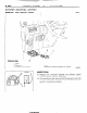
CIRCUIT DIAGRAM
WIPER AND WASHER CIRCU
Ignition switch
lattery
-1.SBAz2
Sub fusible link
A-23
0.5-G
1 5-w m5-w
U
2-R
Z-W
Main fusible link A IL
J.
c
7
C
-
-
-
-
-
-
J A
:
II,
L
.
>
0.85-L '
Light
control
relay
P I?
1
-RW
,
Multi-purpose @
fuse
2-B 9
I--
Intermittent wiper control relay
-r
,m:
JJ-
-.
1 C-64
Headlight washer
motor relay
Remarks
(I) For information concernina the
ground points (example: a ),
refer to P.8-7.
(2) The svmbols 0.0. etc. indicate
that the wiring is connected (using
the same numerical symbol) to the
facing page.
(In other words, 0 on the right
page is connected to 0 on the left
page.)
a
c:
m LB
EEEI
L B L1
Wiring color code
B: Black
Br: Brown
LI: Light blue 0: Orange
G: Green
P: Pink
Gr: Gray
R: Red
L: Blue
Y: Yellow
Lg: Light green
W: White
/ STB Revision