
Service manual


8-210
AUTOMATIC FREE-WHEELING HUB INDICATOR SYSTEM
- General Information
EXPLANATION OF INDICATOR OPERATION
.
1.
2.
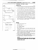
Automatic free-wheeling hub in locked condition
The
output
of the pulse
generator is input to $ertninal
4
of the control unit,
and the output signals from
the vehicle-speed sensor are input
to termi#al
3 of the control unit.
Only when there are pulse signals from the pulse generator, and when, moreover, the vehicle-speed
signals indicate a vehicle speed of approximatkly 2.5 mph (4 km/h) or highter does the control unit judge
that the automatic free-wheeling hub is the locked condition at the lock-discrimination circuit of the
control unit, and therefore the set signal (locked condition) is output.
This signal is entered into the memory circuit, thus causing the indicator light to illuminate.
Pulse generator
Speed sensor
(Reed switch)
Pulse-detection circuit /
I
I
Memory circuit rp*
I
Automatic free-wheeling hub
Lock-discrimin&ion circuit
indicator control unit
16W1535
Ignition switch
‘use No. 3 n
J 2
I_
Power-supply circuit
Vehicle-speed
detection circuit
1
Sub fusible link
1
Main fusible link
1
)
1
Battery
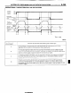
When vehicle is stopped (with ignition key still at ON) with automatic free-wheeling hub locked
Signals are not output from the pulse generator and the vehicle-speed sensor when the vehicle is
stopped.
However, because the set signal (locked condition) is entered into the memory circuit, the indicator light
shows the condition in effect when the vehicle was traveling.
Pulse generator
Speed sense
Pulse-detecti: ci~uit~~I~ #
Lock-discrimination circuit
Memory circuit
‘use No. 3
Ignition switch
10~ Automatic free-
3; wheeling hub
I/\’ indicator light
Sub fusible link
Power-supply circuit
Main fusible link
detection circuit
Automatic free-wheeling hub
indicator control unit
[ STB Revision