
Instruction manual


2 - 30
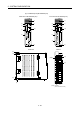
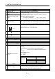
2 SYSTEM CONFIGURATION
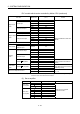
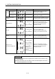
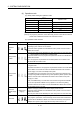
(3) Rotary switch assignment
(a) Rotary function select 1 switch (SW1)
Rotary switch
Setting
(Note)
Mode Description
D
0
8
C
4
F
E
B
A
9
6
7
5
3
2
1
0 Normal mode Normal operation mode
A Installation mode
Installed the operating system software using
MT Developer2
(Note): Do not set other than the above setting.
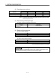
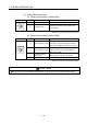
(b) Rotary function select 2 switch (SW2)
Rotary switch
Setting
(Note)
Mode Description
D
0
8
C
4
F
E
B
A
9
6
7
5
3
2
1
0 Mode operated by RAM
Normal operation mode
(Operation by the setting data and parameters
stored in the SRAM built-in Motion CPU module.)
6 Mode operated by ROM
Mode to operate based on the setting data and
parameters wrote to the FLASH ROM built-in
Motion CPU module.
8
Ethernet IP address
display mode
Mode to display the Ethernet IP address.
C SRAM clear SRAM "0" clear
(Note): Do not set other than the above setting.
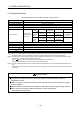
CAUTION
Be sure to turn OFF the Multiple system power supply before the rotary switch setting change.