
Instruction manual


2 - 35
2 SYSTEM CONFIGURATION
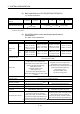
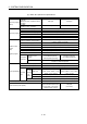
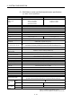
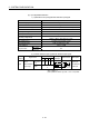
Motion control specifications (continued)
Item Q173DSCPU Q172DSCPU Q173DCPU(-S1) Q172DCPU(-S1)
SSCNET
communication
(Note-8)
Communication
method
SSCNET
/H, SSCNET SSCNET
Number of
lines
2 lines
(Note-9)
1 line
(Note-9)
2 lines 1 line
Driver communication function
(Note-10)
Provided None
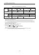
Number of
Motion related
modules
Q172DLX 4 modules usable 2 modules usable 4 modules usable 1 module usable
Q172DEX 6 modules usable 4 modules usable
Q173DPX
4 modules usable
(Note-11)
3 modules usable
(Note-11)
Number of SSCNET /H head
module connection stations
Up to 8 stations usable
(Up to 4 stations/line)
Up to 4 stations usable
Unusable
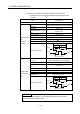
(Note-1): SV22 virtual mode only
(Note-2): Q173DCPU-S1/Q172DCPU-S1 only
(Note-3): When the manual pulse generator is used via the built-in interface in Motion CPU, the Q173DPX cannot be used.
(Note-4): Any incremental synchronous encoder connected to the built-in interface in Motion CPU will automatically be assigned an
Axis No. one integer greater than the number of encoders connected to any Q172DEX modules and Q173DPX modules.
(Note-5): SV22 advanced synchronous control only
(Note-6): Servo amplifier (MR-J4-
B-RJ) only.
(Note-7): This cannot be used in SV22 advanced synchronous control.
(Note-8): The servo amplifiers for SSCNET cannot be used.
(Note-9): SSCNET
and SSCNET /H cannot be combined in the same line.
For Q173DSCPU, SSCNET
or SSCNET /H can be set every line.
(Note-10): Servo amplifier (MR-J3-
B/MR-J4- B) only.
(Note-11): When using the incremental synchronous encoder (SV22 use), you can use above number of modules.
When connecting the manual pulse generator, you can use only 1 module.