
Instruction manual


2 - 53
2 SYSTEM CONFIGURATION
2.5.3. Base unit and extension cable
This section describes the specifications of the extension cables for the base units
(Main base unit or extension base unit), and the specification standards of the
extension base unit.
5VDC internal current consumption of base unit might be changed. Be sure to refer to
the MELSEC-Q series PLC Manuals.
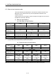
(1) Base unit specifications
(a) Main base unit specifications
Type
Item
Q35DB Q38DB Q312DB
Number of I/O modules 5 8 12
Possibility of extension Extendable
Applicable module Q series modules
5VDC internal current
consumption [A]
0.23 0.23 0.24
Fixing hole size M4 screw hole or 4.5 hole (for M4 screw)
Exterior dimensions
[mm(inch)]
245(W) 98(H) 44.1(D)
(9.65(W) 3.86(H) 1.74(D))
328(W)
98(H) 44.1(D)
(12.91(W) 3.86(H) 1.74(D))
439(W)
98(H) 44.1(D)
(17.28(W) 3.86(H) 1.74(D))
Mass [kg] 0.32 0.41 0.54
Attachment Fixing screw M4 14 5 pieces (DIN rail fixing adapter is optional)
(Note): It is impossible to mount the main base unit by DIN rail when using the Motion CPU module.
Doing so could result in vibration that may cause erroneous operation.
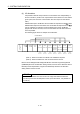
(b) Extension base unit specifications
Type
Item
Q63B Q65B Q68B Q612B
Number of I/O modules 3 5 8
12
Possibility of extension Extendable
Applicable module Q series modules
5VDC internal current
consumption [A]
0.11 0.11 0.12
0.13
Fixing hole size M4 screw hole or 4.5 hole (for M4 screw)
Exterior dimensions
[mm(inch)]
189(W)
98(H)
44.1(D)
(7.44(W) 3.86(H)
1.74(D))
245(W) 98(H)
44.1(D)
(9.65(W) 3.86(H)
1.74(D))
328(W) 98(H)
44.1(D)
(12.91(W) 3.86(H)
1.74(D))
439(W)
98(H)
44.1(D)
(17.28(W) 3.86(H)
1.74(D))
Mass [kg] 0.23 0.28 0.38
0.48
Attachment Fixing screw M4 14 4 pieces
(Note)
(Note): The 5 base mounting screws are included with the Q68B and Q612B that have 5 base mounting holes.