INSTRUCTION MANUAL ORIENTATION CONTROL/PLG FEEDBACK CONTROL/PULSE TRAIN UNIT FR-A5AP TYPE CODE FR-A5AP EIBUN TORISETSU 1A2H59 IB (NA) 66848-A (9803) MEE 1
Thank you for choosing the Mitsubishi transistorized inverter option unit. This instruction manual gives handling information and precautions for use of this product. Incorrect handling might cause an unexpected fault. Before using the equipment, please read this manual carefully to use it to its optimum. Please forward this manual to the end user.
SAFETY INSTRUCTIONS 1. Electric Shock Prevention WARNING While power is on or when the inverter is running, do not open the front cover. You may get an electric shock. Do not run the inverter with the front cover removed. Otherwise, you may access the exposed high-voltage terminals and charging part and get an electric shock. If power is off, do not remove the front cover except for wiring or periodic inspection. You may access the charged inverter circuits and get an electric shock.
3. Additional instructions Also note the following points to prevent an accidental failure, injury, electric shock, etc.: (1) Transportation and installation CAUTION Do not install or operate the option unit if it is damaged or has parts missing. Do not stand or rest heavy objects on the product. Check that the mounting orientation is correct. Prevent screws, metal fragments, conductive bodies or oil, other flammable substance from entering the inverter.
CAUTION When parameter clear or all parameter clear is performed, each parameter returns to the factory setting. Re-set the required parameters before starting operation. For prevention of damage due to static electricity, touch nearby metal before touching this product to eliminate static electricity from your body. (4) Maintenance, inspection and parts replacement CAUTION Do not test the equipment with a megger (measure insulation resistance).
1 PRE-OPERATION INSTRUCTIONS 1.1 Unpacking and Product Confirmation 1.2 Packing Confirmation 1.3 Structure 2 INSTALLATION 2.1 Pre-Installation Instructions 2.2 Installation Procedure 2.3 Wiring 3 ORIENTATION CONTROL 3.1 Wiring Example 3.2 Input Circuit 3.3 Terminals 3.4 Wiring Instructions 3.5 Related Parameter List 3.6 Pre-Operation Settings 3.7 Operation 3.8 Instructions 3.9 Specifications 4 PLG FEEDBACK CONTROL 4.1 Wiring Example 4.2 Input Circuit 4.3 Terminals 4.4 Wiring Instructions 4.
5 PULSE TRAIN INPUT 5.1 Wiring Example 5.2 Terminals 5.3 Adjustment 5.4 Parameter Definition 5.5 Setting Example 5.
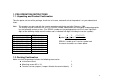
PRE-OPERATION INSTRUCTIONS 1. PRE-OPERATION INSTRUCTIONS 1.1. Unpacking and Product Confirmation Take the option unit out of the package, check the unit name, and confirm that the product is as you ordered and intact. Note: This product may be used with the inverter manufactured during and after February, 1998. The inverter may be used with this unit if its SERIAL number indicated on the rating plate and package plate has the following version or later.
1.3.
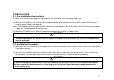
I.ISTALLATION 2.INSTALLATION 2.1. Pre-Installation Instructions (1) Make sure that the input power of the inverter is off and make sure the charge light is off. (2) When the FR-A5AP unit is used for PLG feedback control or orientation control, a PLG (motor with PLG) and external power supply are required. When PLG feedback control and orientation control are used together, the PLG (motor with PLG) and external power supply are shared between these controls.
2.3. Wiring Route the cables so that they do not take up a large space in the control circuit terminal block wiring area of the option unit. Wire the twisted pair shielded cable after stripping its sheath to make its cables loose. Also, protect the shield cable of the twisted pair shielded cable to ensure that it will not make contact with the conductive area. Note: During wiring, do not leave wire off-cuts in the inverter. They can cause a fault, failure or malfunction.
3. ORIENTATION CONTROL This function is used with a position detector (PLG) installed to the spindle of a machine tool (or the motor) to allow a rotary shaft to be stopped at the specified position (oriented). Pr. 350 "stop position command selection" is factory-set to "9999" to make the orientation control function invalid. 3.1.
Note: 1. When the motor with a PLG used is other than the standard motor with PLG (SF-JR), the pin numbers are different. To reduce radiated noise, connect the shield wires of the PLG cables to the CG. 2. When orientation control is used with PLG feedback control, the PLG and 5V power supply may be shared between these controls. 3. Couple the PLG in line with the motor with a speed ratio of 1 to 1 without any mechanical looseness. 4. Keep the accessory jumpers connected.
3.3.
Symbol X22 (Note 1) Terminal Orientation command input terminal Common terminal Remarks ORA (Note 2) In-position signal output terminal ORM (Note 2) Orientation fault signal output terminal Open collector output. Permissible load 24VDC, 0.1A Open collector output. Permissible load 24VDC, 0.1A SE Open collector output common terminal SD Description Used to enter an orientation signal. Common terminal for the orientation signal.
Symbol X0 to X11 FRA5AX input terminal s Inverter input terminal s Terminal Digital signal input terminals DY Data read timing input signal SD Common terminal (sink) External transistor common terminal (source) PC Remarks Use a micro current switching contact relay for the relay contact.
3.4. Wiring Instructions (1) Connection with the position detector (PLG). Use twisted pair shielded cables (0.2mm2 or larger) to connect the FR-A5AP and position detector (PLG). Cables to terminals 5V and SG should be connected in parallel or be larger in size according to the cable length table as indicated below. To protect the cables from noise, run them (at least 10cm) away from any source of noise (e.g. the main circuit and power supply voltage).
3) Connection with NC. (Or similar device) When one position detector is shared between the FR-A5AP and NC (or another device), its output signals should be connected as shown below. In this case, the cable length between the FR-A5AP and NC should be as short as possible, within 5m. Position detector PLG Inverter FR-A5AP NC Max. 5m (2 parallel cables) (3) Connection of terminal resistors.
(4) Position detector (PLG). Line driver LED type PLG A. A signal 1000ppr to 4096ppr B. B signal 1000ppr to 4096ppr C(Z).C(Z) signal 1ppr Output pulse specifications P a b c d A A B B C C 2.4 to 5.25V H 1000ppr to 4096ppr L 0 to 0.4V1000ppr to 4096ppr 1000ppr to 4096ppr 1000ppr to 4096ppr 1ppr 1ppr a, b, c and d should be (1/4 1/8)P when rotation is clockwise as viewed from the shaft end of the PLG.
3.5. Related Parameter List Parameter Number 350 Name Setting Range 0, 1, 9999 0 to 30Hz 0 to 10Hz 0 to 16383 (Note) 0 to 8191 0.01Hz 0.
3.6. Pre-Operation Settings (1) Pr. 350 "stop position command selection". For the stop position command, either the internal stop position command or the external stop position command using external signals (12-bit data) may be selected. Set "9999" in Pr. 350 to make orientation control invalid. Pr. 350 Setting 0 1 9999 Description Internal stop position command External stop position command Orientation control invalid (factory setting) (2) Pr. 369 "number of PLG pulses".
(4) Pr. 356 "internal stop position command". Set "0" in Pr. 350 "stop position command selection" to choose the internal position command mode. In the internal position command mode, the value set in Pr. 356 is processed as the stop position command. When the PLG pulse count is 1024ppr, one revolution of the PLG (360 degrees) is divided into 4096 positions, i.e. 360 degrees/4096 = 0.0879 degrees per address (see below). The stop positions (addresses) are indicated in parentheses.
[Example 1] 4 stop positions Origin (0) 270 (3 or more) [Example 3] 120 stop positions [Example 2] 8 stop positions CW 90 (1) (7 or more) Origin (0) 45 (1) 315 (6)270 90 (2) Pr. 360 = "3" CW 270 (H5A) At intervals 90 of 3 (H1E) 135 (3) (5)225 180 (2) Origin (0) 180 (4) Pr. 360 = "7" 180 (H3C) Note: Values in parentheses indicate binary data entered from the input terminals of the FR-A5AX. If the position signal monitoring (Pr.
(7) Pr. 363 "in-position signal output delay time". When the motor shaft enters the in-position zone, the in-position signal is output after a delay of the time set in Pr. 363. Also, when the motor shaft comes out of the in-position zone, the in-position signal is switched off after a delay of the time set in Pr. 363. (8) Pr. 364 "PLG stop check time".
3.7. Operation (1) Orientation starting during rotation. 1) The orientation command (X22) causes the motor to decelerate to the orientation speed set in Pr. 351. 2) After the orientation speed is reached, the motor decelerates to the creep speed set in Pr. 352 as soon as the current position signal reaches the creep select position set in Pr. 353. 3) Furthermore, the position loop begins to work as soon as the current position signal reaches the position loop select position set in Pr. 354.
9) The in-position signal (ORA) and orientation fault signal (ORM) are not output if the orientation command is off. CAUTION If the orientation command is switched off with the start signal on, the motor accelerates to the command speed. Orientation speed Creep selection Position loop Origin Orientation DC dynamic braking start position Position loop selection Creep speed Operation Timing Chart Spindle speed (PLG) Orientation speed (set in Pr. 351) Creep speed (set in Pr.
(2) Orientation starting during stop. Switch on the orientation command (X22), then switch on the start signal to start and accelerate the motor to the orientation speed set in Pr. 351 and perform orientation using the same procedure as in Section (1). Note that if the current position signal is within the DC dynamic braking start position, the spindle speed will not rise to the orientation speed and the DC dynamic brake is applied.
(3) Multi-position orientation. Orientation starting with orientation command and STF/STR kept on (Orientation starting in the servo-in state) Orientation speed Creep speed Spindle speed (PLG) Start signal Orientation command In-position signal Servo torque Servo torque DY 200ms or longer Position signal Position command latch Position command latch Position data is read on the leading edge of DY (refer to the FR-A5AX instruction manual).
(4) Pr. 358 "servo torque selection" Pr. 358 Setting Remarks Function 0 1 2 3 4 5 6 7 8 9 10 11 12 13 1) Selection of servo torque function until output of inposition signal 2) Retry function selection X O O O O X O X O X O X X O O:Servo torque function valid X:Servo torque function invalid X X X X X X X O X X X O X X 3) Output frequency is compensated for when motor shaft stops outside in-position zone.
1) Selection of servo torque function until the in-position signal is output. Set Pr. 358 "servo torque selection" to determine whether servo torque is required or not. When the current position signal is between the orientation stop position and DC dynamic braking start position, servo torque is not generated. The shaft is held by DC dynamic braking. If the current position signal comes out of this zone due to external force, etc.
(5) Pr. 362 "position loop gain" When Pr. 358 "servo torque selection" value has been set to choose the servo torque function, the output frequency provided to generate servo torque rises gradually up to the creep speed set in Pr. 352 according to the inclination set in Pr. 362 "position loop gain". Increasing the setting will increase the operation speed but may cause the machine to hunt. (6) Monitoring functions Monitoring Position signal monitoring Orientation status Description Set "19" in Pr.
3.8. Instructions (1) The PLG should be coupled with the motor shaft or the spindle oriented with a speed ratio of 1 to 1 without any mechanical looseness. (2) The DC dynamic brake operated for positioning must be released in the shortest time (within several seconds). Operating the brake continuously can cause the motor to generate heat and burn out. (3) The servo lock function is not available after positioning stop.
3.9. Specifications Stop position accuracy Permissible rotation speed Functions Holding force after positioning Input signals (contact input) Output signals (open collector output) DC power supply 1.5 degrees Note: Depends on the load torque, load GD2, orientation speed, creep speed, position loop select position, etc. PLG-mounted shaft speed (6000r/min) Note: The motor and PLG-mounted shaft must be coupled directly or via a belt without any slip. A gear change type cannot be used.
I.PLG FEEDBACK CONTROL 4. PLG FEEDBACK CONTROL This function is used with a speed detector (PLG) to allow the motor speed to be detected by the speed detector and fed back to the inverter so that the output frequency of the inverter is controlled to keep the motor speed constant to load variations. Pr. 367 "speed feedback range" is factory-set to "9999" and Pr. 370 "control mode selection" to "0", making this function invalid. 4.1.
Note: 1. When the motor with PLG used is other than the standard motor with PLG (SF-JR), the pin numbers are different. To reduce radiation noise, connect the shield wires of the PLG cables to the case earth pin. 2. When PLG feedback control is used with orientation control, the PLG and 5V power supply may be shared between these controls. 3. Couple the PLG in line with the motor with a speed ratio of 1 to 1 without any mechanical looseness. 4. Keep the accessory jumpers connected.
4.3. Terminals Symbol PA1 PA2 PAR Terminal PLG A-phase signal input terminal PLG A-phase inverse signal input terminal PLG B-phase signal input terminal PLG B-phase inverse signal input terminal A-phase terminal resistor terminal PBR B-phase terminal resistor terminal 5V SG DC power (positive) input terminal DC power ground terminal PB1 PB2 Remarks Description For information on the pulse signals, refer to page 30. A and B-phase signals are input from the PLG. 4.
4.4. Wiring Instructions (1) Connection with the speed detector (PLG). Use twisted pair shielded cables (0.2mm2 or larger) to connect the FR-A5AP and speed detector (PLG). Cables to terminals 5V and SG should be connected in parallel or be larger in size according to the cable length table as indicated below. To protect the cables from noise, run them (at least 10cm) away from any source of noise (e.g. the main circuit and power supply voltage). (2) Cable length. 1) Cable length within 30m.
(4) Speed detector (PLG) Line driver LED type PLG A. A signal 1000ppr to 4096ppr B. B signal 1000ppr to 4096ppr Output pulse specifications a P b c d A A 2.4 to 5.2V (High) 0 to 0.4V (Low) B B a, b, c and d should be (1/4 1/8)P when rotation is clockwise as viewed from the shaft end of the PLG.
4.5. Related Parameter List Parameter Number 22 29 144 162 Setting Range Minimum Setting Increments 0.1% Factory Setting 0, 1, 2, 3, 4 0, 2, 4, 6, 8, 10, 102, 104, 106, 108, 110 0, 1, 2 1 1 0 4 (Note 4) (Note 4) 1 0 0 to 30Hz, 9999 0, 1 0 to 400Hz, 9999 0 to 100 0 to 4096 0, 1, 2 0, 1 0 to 200% 0 to 200% 0 to 400Hz 0 to 150 0 to 50% 0 to 50% 0 to 50% 0 to 50% 0.01Hz 1 0.01Hz 9999 1 9999 0.1 1 1 1 0.1% 0.1% 0.
4.6. Pre-Operation Settings (1) Pr. 144 "number of motor poles (PLG)". The either of the following motors may be used. Set the number of motor poles according to the motor used: Standard motor (with PLG) : SF-JR 0.2kW to 55kW Constant-torque motor (with PLG): SF-JRCA 0.4kW to 55kW Note: 1. For vector control, this parameter value is made invalid and the setting of Pr. 81 "number of motor poles" is made valid. 2. If you set this parameter value to "0, 10 or 110" and operate the inverter, any of E.OP1 to E.
4.7. Control Mode Setting By setting the Pr. 370 "control mode selection" value, you can choose any of PLG feedback control (V/F control, advanced magnetic flux vector control) and vector control. Torque control and position control are not performed. (However, torque limit can be done in the vector control mode.) When holding torque is required during a stop, choose vector control (zero speed control or servo lock).
4.8. PLG Feedback Control Make sure that Pr. 80 "motor capacity", Pr. 81 "number of motor poles", Pr. 144 "number of motor poles", Pr. 369 "number of PLG pulses", Pr. 359 "PLG rotation direction" and Pr. 370 "control mode" values are set properly. (Refer to Section 4.6 "Pre-Operation Settings and 4.7 "Control Mode Setting".) (1) Pr. 367 "speed feedback range". This parameter is used to make the PLG feedback function valid. Set the speed feedback control range. (When Pr.
(2) Pr. 368 "feedback gain". This parameter is valid when PLG feedback control is valid. Set if rotation is instable or response is slow. When the setting is greater than 1, response is faster but overcurrent or rotational instability is more liable to occur. When the setting is less than 1, response is slower but rotation is more stable. (3) Instructions for PLG feedback control. 1) The number of motor poles used must be checked before starting operation.
9) Set Pr. 285 "overspeed detection frequency" to prevent misoperation caused if an accurate signal cannot be detected from the PLG. This shuts off the output and gives an inverter alarm (E.MB1) when; (detection frequency) - (output frequency) > Pr. 285. 4.9. Vector control Vector control can be performed using the standard motor with PLG. Make sure that Pr. 80 "motor capacity", Pr. 81 "number of motor poles", Pr. 144 "number of motor poles", Pr. 369 "number of PLG pulses", Pr.
1) Zero speed control or servo lock is made valid when the auxiliary exciting terminal (LX) is ON without the start signal (STF, STR) being entered into the inverter (during a stop). Assign the function of the auxiliary exciting terminal (LX) to any of the terminals using Pr. 180 to Pr. 186.
3) Zero speed control or servo lock is made valid when the frequency command is not more than the DC dynamic brake frequency during deceleration of the inverter. The position at the DC dynamic brake operation frequency is held.
(2) Pr. 22 "torque limit level" Torque limit may be activated only when vector control is selected. The second and third functions are Pr. 48 "second torque limit level" and Pr. 144 "third torque limit level". When vector control is not selected, the stall prevention functions are activated. Use the same parameter numbers for setting. The Pr. 22 setting may be changed during operation. When Pr. 22 = "9999", the torque limit level may be set by entering a signal into the No. 1 terminal.
Torque Characteristic of the Standard Motor with PLG (Example: SF-JR Standard Motor with PLG (4 poles)) With Reference to 1800r/min (60Hz) Torque Cyclic operation mode setting Continuous operation mode setting [When the inverter used has a capacity one rank higher [ When the inverter used has the same capacity as than that of the motor and the rated voltage is input] that of the motor and the rated voltage is input] 150 Short-duration maximum torque 150 50%ED (Note 2) 100 2.
(4) Pr. 372 "speed control P gain". Used to set the proportional gain of the speed loop. A high setting will make the speed response faster but if the setting is too high this will cause vibrations and noise. (5) Pr. 373 "speed control I gain". Used to set the integral gain of the speed loop. A high setting will shorten restoration time at occurrence of speed variation but if the setting is too high this will cause speed overshooting. (6) Driving/regenerative status signal output.
10) In the vector control mode, the carrier frequency is as follows: Pr. 72 Setting 0 1 2 3 4 5 6 7 8 9 10 11 12 13 14 15 Carrier Frequency V/F control, advanced Vector control magnetic flux vector control 0.7kHz Approximately 1kHz 1kHz 2kHz 3kHz Approximately 3kHz 4kHz 5kHz 6kHz 7kHz 8kHz 9kHz (Note 1) Approximately 6kHz 10kHz 11kHz 12kHz 13kHz 14kHz 14.5kHz Note: 1. When the capacity of the inverter is the same as that of the motor, do not set "6" or a higher value in Pr. 72 "PWM frequency selection".
4.10. Additional Functions (1) Pr. 162 "selection of automatic restart after instantaneous power failure selection". By setting "2" in Pr. 162, automatic restart after instantaneous power failure can be made at the frequency detected from the PLG. In the vector control mode, automatic restart is made with the PLG detection frequency searched for, independently of the Pr. 162 setting. Pr.
(3) Pr. 374 "overspeed detection level". Used to limit the maximum speed. (0 to 400Hz) Any speed higher than the speed set in Pr. 374 is judged as overspeed and the corresponding signal is output. If overspeed is detected, the inverter will not come to an alarm stop. Speed (r/min) Speed set in Pr. 374 Pr.374 Time Overspeed detection output (Y29) (Note) OFF ON Note: Assign the function to any of the terminals using Pr. 190 to Pr. 195 "output terminal function selection".
(5) S-shaped acceleration/deceleration C When the FR-A5AP is fitted, S-shaped acceleration/deceleration C can be selected by setting "4" in Pr. 29 "acceleration/deceleration pattern". The S-shaped acceleration/deceleration C function allows the speeds of Sshaped acceleration/deceleration to be set in the corresponding parameters and the required parameter to be selected by the S-shaped acceleration/deceleration C switching terminal (X20).
4.11. Specifications Speed variation ratio Speed control range Functions DC power supply Maximum speed Frequency response Note: 1. 0.02% of the maximum speed (3600r/min) in vector control mode (Note 1) (load variation 0 to 100% at 6Hz or more). 1:1000 in vector control mode. Speed feedback range setting. Feedback gain setting. PLG rotation direction setting. A 5VDC power supply is required for the PLG and option unit.
5. Wiring Example I. PULSE TRAIN INPUT A pulse train signal can be used to enter the speed setting of the inverter. Pr. 384 is factory set to "0" to make this function invalid. 5.1.
Output frequency 5.3. Adjustment Factory setting (60Hz) Bias Pr.385 Note: Maximum number of input pulses: 100kpps Note: Number of input pulses are multiplied by 2 internally Gain Pr.386 0 Maximum number of pulses Input pulses (PPS) 5.4. Parameter Definition Parameter No. (Note 1) 384 385 386 Name Input pulse frequency division ratio Zero-input pulse frequency Maximum-input pulse frequency Setting Range 0 to 250 0 to 400Hz 0 to 400Hz Minimum Increments 1 0.01Hz 0.
5.5. Setting Example NFB Power supply Inverter R (L1) U S (L2) Frequency setting potentiometer e.g. pulse generator V T (L3) W FR-A5AP Motor IM 0 to 60Hz Preset frequency When the frequency is set to 0 to 60Hz at the input pulse frequency setting of 0 to 50kpps. Hz 60 0 50kpps Input pulse frequency 0 to 50kpps 1) From the maximum number of input pulses, calculate the Pr. 384 "input pulse frequency division ratio" value. Maximum number of input pulses(pps) Pr. 384 = 400 50000 = Set 125 in Pr.
Input example (Pr. 386 = 400Hz) Input Pulse Frequency Division Ratio (Pr. 384) Maximum Number of Input 0 (factory setting) 20 50 100 120 200 250 Minimum Detectable * Pulses 1 Pulse input invalid 8kpps 20kpps 40kpps 48kpps 80kpps 100kpps * Frequency 2 1.5Hz 1.0Hz 0.5Hz 0.5Hz 0.5Hz 0.5Hz How to calculate the input pulse frequency division ratio Use the following formula to calculate the input pulse frequency division ratio in Pr. 384: *1. Maximum number of input pulses (pps) = Pr. 384x400 Pr.