MELDAS is a registered trademark of Mitsubishi Electric Corporation. Other company and product names that appear in this manual are trademarks or registered trademarks of their respective companies.
Introduction Thank you for selecting the Mitsubishi numerical control unit. This instruction manual describes the handling and caution points for using this AC servo/spindle. Incorrect handling may lead to unforeseen accidents, so always read this instruction manual thoroughly to ensure correct usage. Make sure that this instruction manual is delivered to the end user. Always store this manual in a safe place. All specifications for the MDS-C1-SPA Series are described in this manual.
Precautions for safety Please read this manual and auxiliary documents before starting installation, operation, maintenance or inspection to ensure correct usage. Thoroughly understand the device, safety information and precautions before starting operation. The safety precautions in this instruction manual are ranked as "WARNING" and "CAUTION". DANGER WARNING CAUTION When there is a potential risk of fatal or serious injuries if handling is mistaken.
WARNING 1. Electric shock prevention Do not open the front cover while the power is ON or during operation. Failure to observe this could lead to electric shocks. Do not operate the unit with the front cover removed. The high voltage terminals and charged sections will be exposed, and can cause electric shocks. Do not remove the front cover even when the power is OFF unless carrying out wiring work or periodic inspections. The inside of the units is charged, and can cause electric shocks.
CAUTION 3. Various precautions Observe the following precautions. Incorrect handling of the unit could lead to faults, injuries and electric shocks, etc. (1) Transportation and installation Correctly transport the product according to its weight. Use the servomotor's hanging bolts only when transporting the servomotor. Do not transport the servomotor when it is installed on the machine. Do not stack the products above the tolerable number.
CAUTION Store and use the units under the following environment conditions.
CAUTION (2) Wiring Correctly and securely perform the wiring. Failure to do so could lead to runaway of the servomotor. Do not install a condensing capacitor, surge absorber or radio noise filter on the output side of the servo drive unit. Correctly connect the output side (terminals U, V, W). Failure to do so could lead to abnormal operation of the servomotor. Do not directly connect a commercial power supply to the servomotor. Failure to observe this could result in a fault.
CAUTION (3) Trial operation and adjustment Check and adjust each program and parameter before starting operation. Failure to do so could lead to unforeseen operation of the machine. Do not make remarkable adjustments and changes as the operation could become unstable. (4) Usage methods Install an external emergency stop circuit so that the operation can be stopped and power shut off immediately.
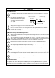
CAUTION (5) Troubleshooting If a hazardous situation is predicted during power failure or product trouble, use a servomotor with magnetic brakes or install an external brake mechanism. Use a double circuit configuration that allows the operation circuit for the magnetic brakes to be operated even by the external emergency stop signal. Shut off with the servomotor brake control output. Servomotor MBR Shut off with NC brake control PLC output.
CONTENTS 1. Installation 1-1 Installation of spindle motor ................................................................................................. 1-2 1-1-1 Environmental conditions .............................................................................................. 1-2 1-1-2 Shaft characteristics ...................................................................................................... 1-2 1-2 Installation of the control unit .................................................
4. Spindle Adjustment 4-1 D/A output specifications for spindle drive unit ................................................................... 4-2 4-1-1 D/A output specifications ............................................................................................... 4-2 4-1-2 Setting the output data .................................................................................................. 4-2 4-1-3 Setting the output magnification .............................................................
Appendix 3. EMC Installation Guidelines Appendix 3-1 Introduction ........................................................................................................ A3-2 Appendix 3-2 EMC instructions ............................................................................................... A3-2 Appendix 3-3 EMC measures.................................................................................................. A3-3 Appendix 3-4 Measures for panel structure...................................
Contents for MDS-C1-SPA Series SPECIFICATIONS MANUAL (IB-1500150) 1. Introduction 1-1 Appendix 1. Outline Dimension Drawings 1-1-1 System configuration .................................................1-2 Outline dimension drawings of spindle motor .................................................. A1-2 1-1-2 Unit outline type.........................................................1-3 Appendix 1-1-1 SJ Series ...................................................A1-2 Explanation of type...............
Contents for MDS-C1-SPA Series SPECIFICATIONS MANUAL (IB-1500150) Appendix 7. EMC Installation Guidelines Appendix 7-1 Appendix 7-2 Appendix 7-3 Appendix 7-4 Introduction .........................................A7-2 EMC instructions .................................A7-2 EMC measures ...................................A7-3 Measures for panel structure ..............A7-3 Appendix 7-4-1 Measures for control panel unit..................A7-3 Appendix 7-4-2 Measures for door...................................
1. Installation 1-1 Installation of spindle motor ............................................................................................................... 1-2 1-1-1 Environmental conditions ............................................................................................................ 1-2 1-1-2 Shaft characteristics .................................................................................................................... 1-2 1-2 Installation of the control unit ................
1. Installation 1-1 Installation of spindle motor CAUTION 1. Do not hold the cables, axis or detector when transporting the motor. Failure to observe this could lead to faults or injuries. 2. Securely fix the motor to the machine. Insufficient fixing could lead to the motor deviating during operation. Failure to observe this could lead to injuries. 3. When coupling to a servomotor shaft end, do not apply an impact by hammering, etc. The detector could be damaged. 4.
1. Installation 1-2 Installation of the control unit CAUTION 1. Install the unit on noncombustible material. Direct installation on combustible material or near combustible materials may lead to fires. 2. Follow the instructions in this manual and install the unit while allowing for the unit weight. 3. Do not get on top of the units or motor, or place heavy objects on the unit. Failure to observe this could lead to injuries. 4. Always use the unit within the designated environment conditions. 5.
1. Installation 1-2-2 Installation direction and clearance Wire each unit in consideration of the maintainability and the heat dissipation, as well as secure sufficient space for ventilation. 75mm or more 100mm or more 100mm or more 10mm or more 10mm or more 100mm or more CAUTION 50mm or more 100mm or more 50mm or more 100mm or more 100mm or more The ambient temperature condition for the power supply unit or the drive units is 55°C or less.
1. Installation 1-2-4 Panel installation hole work drawings (Panel cut drawings) Prepare a square hole to match the unit width. 360 Square hole 342 [Unit: mm] (Note 1) 82 2-M5 screw Unit width: 90mm 112 2-M5 screw (Note 1) 4-M5 screw Unit width: 120mm POINT 142 Unit width: 150mm Attach packing around the square hole to provide a seal.
1. Installation 1-2-5 Heating value Each heating value is calculated with the following values. The values for the spindle drive unit are for a continuous rated output. The value for the power supply unit includes the AC reactor's heating value.
1. Installation 1-2-6 Heat radiation countermeasures In order to secure reliability and life, design the temperature in the panel so that the ambient temperature of each unit is 55°C or less. If heat accumulates at the top of the unit, etc., install a fan so that the temperature in the panel remains constant. (Note) Due to the structure, heat easily accumulates at the top of the unit. Install a fan in the power distribution panel to circulate the heat at the top of the unit.
1. Installation Please refer to following method for heat radiation countermeasures. Calculate total heat radiation of each mounted unit (W) Calculate cabinet’s cooling capacity (W1) W ≤ W1 Comparison of W and W1 W>W1 Selection of heat exchanger Mounting design Collection of internal temperature rise distribution data Evaluation ∆T>10°C Improvements Completion 1) Refer to Specifications Manual, etc. for the heat generated by each unit.
1. Installation 1-3 Installing the spindle detector 1-3-1 Magnetic sensor (1) Installing the magnetic sensor • Tolerance to shaft dimension should be "h6" on the part for installing a magnet. • 2-øG hole can be used for positioning of spindle and magnet. • Magnet shall be installed as shown to the right. • Misalignment between sensor head and magnetic center line shall be within ±2mm. • There is an NS indication on the side of the cover.
1. Installation (3) Magnet and sensor installation directions • Install so that the magnet's reference hole and sensor's reference notch are aligned. (Standard/high-speed standards) • Install so that the magnet's N pole comes to the left side when the sensor's reference notch is faced downward. (High-speed compact/high-speed ring) N Sensor S S Magnet | Reference notch Sensor N Magnet | Reference notch (4) Cautions [1] Do not apply impacts on the magnet.
1. Installation 1-3-2 Spindle side detector When coupling the spindle side detector with spindle, a flexible coupling should be used to couple the spindle side detector with the spindle. Detector Flexible coupling 0.02 0.02 Opposite detector shaft side Detector and coupling installation accuracy Recommended coupling Recommendation 1 Recommendation 2 Tokushu Seiko Eagle Model M1 FCS38A 1374Hz 3515Hz 0.8×10⁻³° 1.2×10⁻³° 20000r/min 10000r/min 0.7mm 0.16mm 1.5° 1.5° Max. length 74.
1. Installation 1-4 Noise measures Noise includes "propagation noise" generated from the power supply or relay, etc., and propagated along a cable causing the power supply unit or drive unit to malfunction, and "radiated noise" propagated through air from a peripheral device, etc., and causing the power supply unit or drive unit to malfunction. Always implement these noise measures to prevent the peripheral devices and unit from malfunctioning.
1.
2. Wiring and Connection 2-1 Connection diagram ........................................................................................................................... 2-3 2-1-1 Part system connection diagram.................................................................................................. 2-3 2-1-2 Detailed connection diagram........................................................................................................
2. Wiring and Connection DANGER 1. Wiring work must be done by a qualified technician. 2. Wait at least 15 minutes after turning the power OFF and check the voltage with a tester, etc., before starting wiring. Failure to observe this could lead to electric shocks. 3. Securely ground the drive units and spindle motor. 4. Wire the drive units and spindle motor after installation. Failure to observe this could lead to electric shocks. 5.
2.
2.
2.
2.
2. Wiring and Connection 2-2 Main circuit terminal block/control circuit connector 2-2-1 Names and applications of main circuit terminal block signals and control circuit connectors The following table shows the details for each terminal block signal. Name Signal name L1 . L2 . L3 Main circuit power supply Control circuit power supply Description MC1 Contactor control U.V.
2. Wiring and Connection 2-2-2 Connector pin assignment Do not apply a voltage other than that specified in Instruction Manual on each terminal. Failure to observe this item could lead to rupture or damage, etc.
2. Wiring and Connection Spindle drive unit Unit MDS-C1-SPA-55 to 300 Terminal Terminal position [2] [3] [1] [4] U V W Terminal specification/Pin assignment [1] [2] [3] [4] TE1 MDS-C1-SPA- 55 to 185 220 to 300 Screw size Tightening torque M5 3.2Nm M8 13.2Nm L+ Compatible unit All capacity L- Screw size Tightening torque M6 5.0Nm Compatible unit All capacity Screw size Tightening torque M4 2.0Nm TE2 TE3 L11 L21 The PE screw size is the same as TE1.
2. Wiring and Connection (2) Control circuit connector Unit MDS-C1-SPA-55 to 300 Terminal Connector position [1] [2] [3] [4] [5] [6] [7] [9] [1] CN11 [2] CN12 [3] CN9A [4] CN4 [5] CN5 [6] CN6 [7] CN10 [8] CN8A Pin No. [5] CN5 Connector specifications GND RD MOH SD P15 PA PB PZ P24 - 11 12 13 14 15 16 17 18 19 20 GND RD* RG SD* N15 RA RB - 11 12 13 14 15 16 17 18 19 20 No.
2. Wiring and Connection 2-3 Drive unit connection In this section, the connection between the spindle drive unit and power supply unit is shown. There is space between units in the following diagram to make clearly understandable. However, actually, install the drive units so that the space between the drive units is within 3cm. POINT Even if two or more spindle drive units are used, keep the setting of the spindle drive unit’s rotary switch to “0”. This switch has no relation to the axis No.
2. Wiring and Connection (2) When using two power supply units and connecting one spindle drive unit with each power supply unit Two or more power supply units may be required if the spindle drive unit capacity is large in a machine applying two spindles specification. Make sure that the powers (L+, L-) of both power supply units are supplied to only one spindle drive unit connected with each power supply, and do not connect each other's powers. MDS-C1-SPA MDS-C1-CV MDS-C1-SPA MDS-C1-CV (No.1) (No.
2. Wiring and Connection (3) When connecting two or more spindle drive units with one power supply unit Connect units according to the following cautions. MDS-C1-SPA MDS-C1-CV (No.1) MDS-C1-SPA MDS-C1-SPA (No.2) (No.3) CN4 CN4 CN4 CN9 Connections when sharing one power supply (Note 1) Connecting power supply unit and spindle drive unit. Connect C1-CV CN4 and C1-SPA (No. 1) CN4 to C1-CV CN9 and C1-SPA (No.2) CN4. If C1-SPA is connected with three or more axes, leave CN4 for C1-SPA (No.
2. Wiring and Connection 2-4 Motor and detector connection 2-4-1 Connection of the spindle motor Refer to each motor specifications for details on the motor side connection destination, specifications and outline, and for the spindle PLG detector specifications. (1) Connecting the motor built-in PLG MDS-C1-SPA Detector connector : CN5 Pin No. CN5 Max. 30m Option cable : CNP5 No.1 No.11 No.10 No.
2. Wiring and Connection (2) Connecting the magnetic sensor Refer to section (1) for connection with the spindle motor. MDS-C1-SPA Detector connector : CN6 Pin No. Max. 30m Option cable : CNP5 CN5 CN6 No.1 No.11 No.10 No.20 Pin Name 1 2 3 4 5 P15(+15V) 6 MAG 7 LS 8 9 10 Pin 11 12 13 14 15 16 17 18 19 20 Name LG MAGR LSR Power cable U V W U VW Spindle motor Magnetic sensor Spindle Option cable : CNP6M CAUTION 1. The shield of spindle detector cable is not FG. Do not ground. 2.
2. Wiring and Connection (3) Connecting the spindle side detector Refer to section (1) for connection with the spindle motor. MDS-C1-SPA Detector connector : CN6 Pin No. CN5 Max. 30m CN6 No.1 No.11 No.10 No.20 Option cable : CNP5 Pin 1 2 3 4 5 6 7 8 9 10 Name LG MA MB MZ P5(+5V) Power cable U V W U VW Spindle motor Spindle Spindle side detector Option cable: CNP6A CAUTION The shield of spindle detector cable is not FG. Do not ground.
2. Wiring and Connection 2-5 Connection of power supply CAUTION 1. Make sure that the power supply voltage is within the specified range of each unit. Failure to observe this could lead to damage or faults. 2. For safety purposes, always install a No-fuse breaker (NFB), and make sure that the circuit is cut off when an error occurs or during inspections. 3. The wire size will differ according to each drive unit capacity. 4.
2. Wiring and Connection (2) When using two power supply units, and connecting one spindle drive unit with each power supply unit Install a no-fuse breaker and a contactor for each of the power supply units. Install the drive units so that the distance between power supply unit and spindle drive unit will be 3cm or less. The installation distance between No.1 and No.2.is not particularly specified. MDS-C1-CV(No.
2. Wiring and Connection (3) When connecting one power supply unit with two spindle drive units Only the spindle drive unit connected to the power supply unit's CN4 connector becomes the power supply unit control axis. MDS-C1-CV MDS-C1-SPA(No.1) CN4 CN4 MDS-C1-SPA(No.2) CN4 CN9 No-fuse breaker AC reactor Contactor R L1 S L2 T L3 TE2 Ground Breaker TE1 MC L+ L+ L- L- TE2 L+ L- TE2 MC1 L11 TE3 L11 TE3 L11 TE3 L21 L21 L21 Ground Ground Ground MDS-C1-SPA(No.
2. Wiring and Connection 2-5-2 Connecting the grounding cable (1) Connecting the protective grounding (PE) and frame ground (FG) Each unit has a terminal or mounting hole to connect PE ( ) or FG. Please connect an earth wire to the main ground of a cabinet or a machine frame at one point. Ground each device according to the grounding conditions set forth by each country. (Typically, a Y-connection neutral point ground is used in Europe.) PE: Grounding to provide protection from electric shock, etc.
2. Wiring and Connection 2-5-3 Main circuit control (1) Contactor ON sequence Main circuit power is turned ON in the sequence shown below when an emergency stop status is canceled.
2. Wiring and Connection (2) Contactor shutoff sequence During the emergency stop signal input (EMG), if the setting of SP193 is "0" or "1" after the spindle motor decelerates to stop, the contactor is turned OFF after a certain amount of time. Even in the emergency stop, the contactor is turned OFF immediately after the machine ready complete signal (RDY) is turned OFF.
2. Wiring and Connection 2-6 Peripheral control wiring 2-6-1 Input interface (1) Digital input interface: CN10 to 12 (Special input: 3 points, general-purpose input: 12 points, multi-points orientation command: 12 points, digital speed command: 12 points) Select from the following. 1) Connecting with contact 2) Connecting with photo coupler +24V +24V Current capacity 5.1mA or more Current capacity 5.1mA or more 4.7KΩ 4.
2. Wiring and Connection (2) Encoder (1024p/rev) input interface When connecting an encoder, +5V must be supplied from the drive unit side. Power does not need to be supplied from the NC(PC) side.
2. Wiring and Connection 2-6-2 Output interface (1) External contact output circuit The drive unit fault output signal FA(CN12-10) and FC(CN12-20) are the outputs. Use the contacts with the rating indicated below. 24VDC 0.3A or less Chattering 5ms or less Compact relay is used. When connecting an inductive load such as relay, preferably use a DC compact relay, and connect a flywheel diode in parallel with the coil as shown in the figure below.
2. Wiring and Connection (3) Open collector output circuit The followings are the open collector outputs.
2. Wiring and Connection 2-6-3 Spindle coil changeover There are spindle motors capable of coil changeover control, which enables favorable characteristics to be attained from low speeds to high speeds by changing two types of coils. (1) Coil changeover control The speed at which to change the coils is detected by the spindle drive according to the value set with spindle parameter SP020. This is conveyed to the NC or PC with a speed detection (SD) signal.
2. Wiring and Connection (2) Protective functions [1] Base shutoff after a winding changeover When the L-coil selection command (LCS) is used to perform low-speed winding → high-speed winding switching, or vice-versa, this base is shut off during contactor operation time in order to protect the spindle drive unit's main circuit. This base shutoff time is determined by the "Winding changeover base shutoff timer" (SP059) setting.
2. Wiring and Connection (3) Wiring The illustration below shows the 2 types of changeover that occur after a coil changeover, (a) Y (star) – ∆ (delta) changeover, and (b) Y (star) – Y (star) changeover. As shown in (c), one of the contactors (MC1 or MC2) is turned ON and the other is turned OFF at all of the coil changeover control circuits.
2. Wiring and Connection 2-6-4 Wiring of an external emergency stop (1) External emergency stop setting Besides the emergency stop input from the NC or PC to spindle drive unit, double-protection when an emergency stop occurs can be provided by directly inputting an external emergency stop to the CN23 connector on the power supply unit.
2. Wiring and Connection (2) Operation sequences of CN23 external emergency stop function If only external emergency stop is input when external emergency stop valid is set in the parameters (the emergency stop is not input in the spindle drive unit), an "In external emergency stop" (warning EA) will be detected. At this time, the spindle drive unit does not enter an emergency stop status. (There will be no deceleration control.
2. Wiring and Connection (3) Example of emergency stop circuit [1] Outline of function The power supply unit's external emergency stop can be validated by wiring to the CN23 connector, and setting the parameters and rotary switch. If the emergency stop cannot be processed and the external contractor cannot be shut off (due to a fault) by the spindle drive unit, the external contactor can be shut off by the power supply unit instead of the spindle drive unit.
3. Setup 3-1 Initial setup........................................................................................................................................ 3-2 3-1-1 Setting the rotary switch ............................................................................................................ 3-2 3-1-2 Transition of LED display after power is turned ON .................................................................. 3-3 3-2 Setting the initial parameters for the spindle drive unit...........
3. Setup 3-1 3-1-1 Initial setup Setting the rotary switch Before turning on the power, the settings of the spindle drive unit and power supply unit's rotary switches must be confirmed and changed. Spindle drive unit (MDS-C1-SPA) Power supply unit (MDS-C1-CV) 5 4 3 67 8 9A B C D 21 FE 0 5 4 3 Setting the rotary switch 0 1 2 3 Details Setting the MDS-C1- SPA Setting the MDS-C1-CV Apply this setting when the power is turned ON.
3. Setup 3-1-2 Transition of LED display after power is turned ON The spindle drive unit and the power supply unit power have been turned ON, each unit will automatically execute self-diagnosis and initial settings for operation, etc. The LEDs on the front of the units will change as shown below according to the progression of these processes. If an alarm occurs, the alarm No. will appear on the LEDs. Refer to "5-1-1 LED display when alarm or warning occurs" for details on the alarm displays.
3. Setup 3-2 Setting the initial parameters for the spindle drive unit The parameters of spindle drive unit must be set before the spindle system can be started up. Basic settings have been provided in shipping. Therefore, for parameters required to be changed individually, they are input with the rotary switch and push button of the drive unit or the personal computer. 3-2-1 Parameter setting method There are two methods of parameter setting as shown below.
3. Setup 3) Set the rotary SW to "2". At this time, the spindle drive unit 7-segment LED indicates the lower two digits of parameter No. Use the UP/DOWN buttons to set the lower two digits of the parameter No. Keep the button pressed to expedite the operation. (Setting example) LED setting Parameter No. value SP001 1 SP010 A SP129 81 SP255 FF SP320 40 (Note that, however, the rotary SW is "1" at this time and so "1" must be set on the right side of LED.) 4) Set the rotary SW to "3".
3. Setup 3-2-2 List of spindle parameters These parameters are sent to the spindle drive unit when the NC power is turned ON. The standard parameters are designated with the "Spindle parameter setting list" enclosed when the spindle motor is delivered. There may be cases when the machine specifications are unclear, so the parameters determined by the machine specifications should be confirmed by the user. Abbr.
3. Setup No. Abbr. Parameter name SP017 TSP Maximum motor speed SP018 ZSP Details Setting range Standard (Unit) setting Set the maximum spindle motor speed. 1 to 32767 (r/min) 6000 Motor zero speed Set the motor speed for which zero-speed signal output is performed. 1 to 1000 (r/min) 50 1 to 32767 (10 ms) 30 SP019 CSN1 Speed cushion 1 Set the time constant for a speed command from "0" to the maximum speed. (This parameter is invalid when the S analog synchronous tapping is valid.
3. Setup No. Abbr. Parameter name Details F E D poff hzs B A ront bit SP033 SFNC1 Spindle function 1 C 9 8 pycal pychg 7 6 5 4 3 pyst pyoff Meaning when set to 0 2 sftk 1 0 dflt 1a2m Meaning when set to 1 Standard 0 1a2m 1 drive unit 2 motor function: Invalid 1 drive unit 2 motor function: Valid 0 1 dflt Default motor: Main Default motor: Sub 0 2 sftk Without SF-TK card With SF-TK card 0 3 0 4 0 5 0 6 pyoff This is set by Mitsubishi.
3. Setup No. Abbr.
3. Setup No. Abbr.
3. Setup No. Abbr. Parameter name Details Setting range Standard (Unit) setting Set the spindle drive unit's capacity type.
3. Setup No. Abbr.
3. Setup No. Abbr. Parameter name Details Setting range Standard (Unit) setting SP046 CSN2 Speed command dual cushion For an acceleration/deceleration time constant defined in SP019 (CSN1) , this parameter is used to provide smooth movement only at the start of acceleration/deceleration. As the value of this parameter is smaller, it moves smoother but the acceleration/deceleration time becomes longer. To make this parameter invalid, set "0".
3. Setup No. Abbr. Parameter name Setting range Standard (Unit) setting Details Set the speed when the speed loop proportional gain change starts. Change starting speed of SP066 VCSN1 variable speed loop proportional gain Proportional gain SP022 SP022× (SP065/100) 0 to 32767 (r/min) 0 Speed SP066 SP017 SP067 VIGWA Change starting speed of Set the speed where the current loop gain change starts.
3. Setup No. Abbr. Parameter name Setting range Standard (Unit) setting Details F E D C B A 9 8 7 6 5 r2iro r2ini bit 0 3 2 1 0 Meaning when set to 0 Meaning when set to 1 Standard r2ch 0 1 no51 0 2 r2dm Set by Mitsubishi. Set "0" unless designated in particular. 0 3 SP075 R2KWS* Fixed control constant 4 r2am r2lm r2dm no51 r2ch r2lm 0 4 r2am 0 5 0 6 0 7 0 8 r2ini 9 r2iro 0 Set by Mitsubishi. Set "0" unless designated in particular.
3. Setup No. Abbr. Parameter name Setting range Standard (Unit) setting Details SP089 Not used. Set "0". 0 0 SP090 Not used. Set "0". 0 0 -2048 to 2047 (-1mV) 0 -2048 to 2047 (-1mV) 0 SP091 Offset compensation OFSN* during motor PLG forward run Set the PLG offset for forward run. Normally "0" is set. SP092 Offset compensation OFSI* during motor PLG reverse run Set the PLG offset for reverse run. Normally "0" is set. SP093 Not used. Set "0".
3. Setup No. Abbr. Parameter name Details SP098 Set the speed loop proportional gain in orientation control Speed loop gain mode. VGOP proportional term in When the gain is increased, rigidity is improved in the orientation control mode orientation stop but vibration and sound become larger.
3. Setup No. SP114 SP115 Abbr. OPER* OSP2* Parameter name Details Setting range Standard (Unit) setting Orientation control pulse miss check value An alarm "5C" will occur if the pulse miss value at the orientation stop exceeds this setting value. (Note that this is invalid when set to "0".) 0 to 32767 In this parameter, set the value to fulfill the following (360 deg/4096) conditions. SP114 setting value > 1.
3. Setup No. Abbr. Parameter name Details Setting range Standard 0 to 21 0 Assign signals to general-input 1 (IN1: CN10-12 pin). Select the signal to be assigned from the table below.
3. Setup No. Abbr. Parameter name Details Setting range Standard 0 to 23 0 Assign signals to general-purpose output (open emitter) 1 (OUT1: CN11-7 pin). Select the signal to be assigned from the table below.
3. Setup Setting range Standard General-purpose output Assign signals to general-purpose output (open collector) selection 1(OUT1c: CN12-7 pin). Open collector 1 The setting method is the same as SP141(HO1e). 0 to 23 0 HO2c General-purpose output Assign signals to general-purpose output (open collector) selection 2(OUT2c: CN12-17 pin). Open collector 2 The setting method is the same as SP141(HO1e).
3. Setup Abbr. SP162 SS00 Speed setting 0 Regardless of whether the speed command mode is analog 0 to 32767 or digital, the motor is run by the value set here when the (r/min) forward/reverse run signal is input. 0 SP163 SS01 Speed setting 1 Set the motor speed command value when the speed 0 to 32767 selection 1 is assigned to the general-purpose input and the (r/min) input is turned ON.
3. Setup Parameter name Abbr. SP178 SMG* Adjust the speed meter full scale. 0 to 1000 Speed meter output full Adjust so that the fluctuations of the speed meter is at the (1/1000-fold scale adjustment intended position when "1" is set in SP177(MADJ). ) 938 SP179 LMG* Load meter output full scale adjustment Adjust the load meter full scale. 0 to 1000 Adjust so that the fluctuations of the load meter is at the (1/1000-fold intended position when "1" is set in SP177(MADJ).
3. Setup Details Setting range (Unit) Standard setting Speed excessive SE2R* deflection 2 detection range Set the speed detection width when the speed excessive deflection 2 alarm is output. The setting is as follows. Detection width = Speed command × current setting value/100 (r/min) When the result of the expression above is smaller than 45r/min, the detection width is clamped at 45r/min. When "0" is set, detection will not be carried out.
3. Setup No. Abbr. Parameter name Details Setting range Standard (Unit) setting SP253 DA1NO* D/A output channel 1 data number Set the output data number for channel 1 of the D/A output function. When set to "0", the output is speedometer. -32768 to 32767 0 SP254 DA2NO* D/A output channel 2 data number Set the output data number for channel 2 of the D/A output function. When set to "0", the output is speedometer.
3. Setup 3-3 3-3-1 Initial adjustment of the spindle PLG Adjusting the PLG installation The PLG (spindle motor speed detector) mounted on the Mitsubishi framed spindle motor is shipped from Mitsubishi in the adjusted state. If there are no particular problems, carrying out the adjustment in this section is not required.
3. Setup (2) Adjusting the gap [1] Confirm that the detection gears are not rotating. The sensor could be damaged if the gap is adjusted while the gears are rotating. [2] Loosen the sensor fixing screw with the sensor fixed on the sensor installation seat. [3] Using a clearance gauge, adjust so that the gap between the sensor detection surface and the detection gears' circumference is 0.15±0.01mm. [4] The sensor can be moved up and down or turned when the sensor fixing screw is loosened.
3. Setup (4) Adjusting the A phase and B phase output signal [1] Set the drive unit in the open loop operation state. (Set the spindle parameter SP038/bitF to "1" and turn the spindle drive unit power ON again.) There are cases when sudden speed changes cannot be followed during open loop operation, so gradually change the speed command. [2] Forward run the motor and rotate the PLG at the reference speed.
3. Setup (5) Confirming the Z phase pulse width Check the output signal waveform by measuring the signals of the check terminals on the PCB with the DC range of the synchroscope. A phase output signal...... Across A-G Z phase output signal...... Across Z-G The output signal waveform is confirmed during motor forward run and reverse run. Set the synchroscope as follows to measure the waveform during each run direction. During forward run ..........
3. Setup (7) Checking the Z phase and A phase difference Check the output signal waveform by measuring the signals of the check terminals on the PCB with the DC range of the synchroscope. A phase output signal...... Across A-G Z phase output signal...... Across Z-G The output signal waveform is confirmed during motor forward run and reverse run. Set the synchroscope as follows to measure the waveform during each run direction. During forward run .....
3. Setup (8) Adjusting the Z phase and A phase difference [1] Stop the motor, and make sure that the detection gears are not rotating. The sensor could be damaged if adjustments are carried out while the gears are rotating. [2] Using a clearance gauge, adjust so that the gap between the sensor direction surface and the detection gears’ circumference is 0.15±0.01mm, and loosen the sensor fixing screw.
4. Spindle Adjustment 4-1 D/A output specifications for spindle drive unit................................................................................. 4-2 4-1-1 D/A output specifications ........................................................................................................... 4-2 4-1-2 Setting the output data............................................................................................................... 4-2 4-1-3 Setting the output magnification ........................
4. Spindle Adjustment 4-1 D/A output specifications for spindle drive unit The spindle drive unit has a function to D/A output each control data. The spindle adjustment data required to set the spindle parameters matching the machine can be D/A output. The data can be measured with a hi-corder or oscilloscope, etc. 4-1-1 D/A output specifications Item Explanation No.
4. Spindle Adjustment 4-1-3 Setting the output magnification (1) Meter output (Data No. 0) With meter output, the output channel is fixed, and the output voltage range is 0 to 10V in the positive range. Set the magnification with the following parameters. Also, low path filter can be set on the load meter output. No. Abbr. SP017 TSP* SP094 Parameter name Maximum motor speed Details Setting range Set the maximum spindle motor speed.
4. Spindle Adjustment (3) Control signal output (Data No. 80 to 87) A hexadecimal display is converted into a decimal and output. The method of calculating the magnification is the same as (2). The status cannot be output for each bit, so output the status for all 16 bits.
4. Spindle Adjustment 4-2 Spindle control signal The sequence input/output signals of the spindle drive unit are explained in this section. The status of each signal is displayed on the spindle monitor of the personal computer when the personal computer is connected.
4. Spindle Adjustment Related spindle parameters No. Abbr. SP129 to SP140 HI01 to HI12 Parameter name General-purpose input selection1 to general-purpose input selection12 Details Set the following value in any one of these parameters when using the alarm reset. “9”: Alarm reset Setting range Standard 0 to 21 0 bit8. Torque limit 1 (TL1) bit9. Torque limit 2 (TL2) bitA.
4. Spindle Adjustment (2) Spindle control input 2 Not used. (3) Spindle control input 3 Name Details Spindle control input 3 F E D C B A 9 8 MsI LCS ORC WRI WRN SRI SRN bit 0 SC1 1 SC2 2 SC3 3 SC4 4 SC5 5 GR1 6 GR2 7 8 SRN 9 SRI A WRN B WRI C ORC D LCS E MsI F bit0. bit1. bit2. bit3. bit4.
4. Spindle Adjustment bit5. Gear selection command 1 (GR1) bit6. Gear selection command 2 (GR2) This selects the number of spindle gear stages required to carry out orientation operation or various position control operation. GR2 GR1 Gear ratio 0 0 SP025, SP029 0 1 SP026, SP030 1 0 SP027, SP031 1 1 SP028, SP032 Related spindle parameters No. Abbr.
4. Spindle Adjustment bit9. Reverse run start command (SRI) This is an operation command. The speed command must also be designated to rotate the motor. If the orientation command is input, the orientation operation will have the priority. This is validated when closing (ON) the circuit between 2 pin (SRI) and 19 pin (CES1) of CN10. SRN Explanation Spindle motor rotation direction 1 (ON) The motor rotates in the clockwise direction (CW) looking from the shaft at the commanded speed.
4. Spindle Adjustment (4) Spindle control input 4 Name Details Spindle control input 4 F 0 1 2 3 4 5 6 7 8 9 A B C D E F E bit Emg ss1 ss2 ss3 deg ovr hsp D C B A 9 8 7 6 5 hsp ovr deg 4 3 2 1 0 ss3 ss2 ss1 Emg Details Emergency stop Speed selection1 Speed selection2 Speed selection3 Digital speed command valid Override input S-analog speed synchronous tapping bit0. Emergency stop (Emg) This signal turns ON when the emergency stop input signal is opened (OFF).
4. Spindle Adjustment bit1. Speed selection 1 (ss1) bit2. Speed selection 2 (ss2) bit3. Speed selection 3 (ss3) This is used to determine the speed command with three inputs. By using the combination of ss1 to 3 input, set the speed command value to the value set in SP162 to SP169. Note that, however, if the value of SP162 is "0" and ss1 to 3 are all OFF, the speed command is the input given by the regular analog voltage.
4. Spindle Adjustment bit5. Digital speed command input valid (deg) This signal turns ON when the digital speed command input is closed (ON). When this signal is turned ON, the speed command is determined by the external input R01(CN12-1 pin) to R12(CN12-16 pin) 12bit. The common is CES2(CN12-19 pin). The types of digital speed command include the followings, and one of them can be selected (by the parameter).
4. Spindle Adjustment 3) Binary (12-bit binary) Rotation speed in respect to command value is as shown below. BINARY code Motor rotation speed (When the max. speed is 10000r/min) Motor rotation speed (When the max. speed is 6000r/min) 000 0r/min 0r/min 001 2r/min 1r/min 002 4r/min 2r/min • • • • • • • • • • • • • • • FFE 9997r/min 5998r/min FFF 10000r/min 6000r/min (Example) Input method is as shown below.
4. Spindle Adjustment Related spindle parameters No. Abbr. Parameter name Details SP129 to SP140 HI01 to HI12 General-purpose input selection 1 to General-purpose input selection 12 Set the following value in any one of these parameters when using the digital speed command. "15": Digital speed command valid (deg) SP156 DGtyp Set the digital speed command input method.
4. Spindle Adjustment 4-2-2 Spindle control output (SP to NC) (1) Spindle control output 1 Name Details Spindle control output 1 F E D C B A CL 9 8 bit 0 1 2 3 4 5 6 7 8 9 A B C D E F 7 6 TL3A TL2A TL1A ALM PRMA 5 4 3 2 1 0 RON WRN Details RON In READY ON WRN In drive unit warning PRMA In parameter conversion ALM In drive unit alarm TL1A TL2A TL3A CL In torque limit 1 signal input In torque limit 2 signal input In torque limit 3 signal input Limiting current bit0.
4. Spindle Adjustment bit7. In drive unit alarm (ALM) This signal turns ON when an alarm is occurring in the spindle drive unit. No. Abbr. SP141 to SP154 HO1e to HO6c Parameter name General-purpose output selection Open emitter 1 to General-purpose output selection Open collector 6 Details Set the following value in any one of these parameters when using the in drive unit alarm output. “9”: In alarm (ALM) Setting range Standard 0 to 23 0 bit8. In torque limit 1 signal input (TL1A) bit9.
4.
4. Spindle Adjustment bit9. Motor in reverse run (SRIA) This signal turns ON while the start signal is input and the motor is rotating in the CW direction looking from the motor shaft. This signal may turn ON and OFF if the motor speed is several r/min or less. No. Abbr.
4.
4. Spindle Adjustment bit1. Speed detection (SD) This signal turns ON when the motor speed drops below the value set with parameter SP020 (SDTS). The ON to OFF hysteresis width is set with parameter SP047 (SDTR). This signal turns ON when the motor's speed is less than the set speed regardless of the input signal state. SP047 Motor speed SP020 0 Speed detection (SD) ON OFF Speed detection (SD) sequence Related spindle parameters No. Abbr.
4. Spindle Adjustment bit2. Up-to-speed (US) This signal turns ON when the start command signal (forward run, reverse run) is ON, and the motor speed has reached a range of ±15% (standard value) of the speed command value. This signal turns OFF when the start command signal turns OFF. The up-to-speed output range can be set with the parameter SP048 (SUT). Even though the setting value is small, the output will be ±45r/min. Pay attention when speed command value is small.
4. Spindle Adjustment bit3. Zero speed (ZS) Regardless of the input signal state, this signal turns ON when the motor speed drops below the value set with parameter SP018 (ZSP). Once this signal turns ON, it will not turn OFF for at least 200ms. When switching ON to OFF, hysteresis width is 15r/min. Note that if the parameter SP018 (ZSP) setting value is too small (approx. 10r/min or less), this signal may not be output even if the motor is stopped.
4. Spindle Adjustment bit4. Orientation complete (ORCA) This signal turns ON when the orientation command is input, and the spindle position is reached the set range (within the in-position range) in respect to the target stop position. This signal turns OFF when orientation is completed and the spindle position deviates from the in-position range, but it will turn ON again when the spindle position enters the in-position range again.
4. Spindle Adjustment bit7. Index positioning completed (WRCF) This signal turns ON during indexing operation when the spindle position reaches the in-position range in respect to the target stop position. Once this signal turns ON it will remain ON regardless of the spindle position until the orientation signal turns OFF or the next indexing operation signal is input.
4. Spindle Adjustment bitA. Torque reach (TLU) This signal turns ON when the start command is input and the torque command in the drive unit reaches to the clamp value. Related spindle parameters No. Abbr. SP141 to SP154 HO1e to HO6c Parameter name General-purpose output selection Open emitter 1 to General-purpose output selection Open collector 6 Details Set the following value in any one of these parameters when using the torque reach output.
4. Spindle Adjustment bitC. Alarm code output1 (AL1) bitD. Alarm code output2 (AL2) bitE. Alarm code output3 (AL3) bitF. Alarm code output4 (AL4) When an alarm occurs in the drive unit, this signal outputs the content of the alarm that occurred in a combination of 4bit. Even if the unit is normal, this signal may turn ON for 1 second after the power is turned ON.
4. Spindle Adjustment 4-3 Adjustment procedures for each control 4-3-1 Basic adjustments (1) Items to check during trial operation [1] Directly couple the motor and machine, and check the control status during machine run-in. [2] Check that the command speed and actual speed match. If the speeds do not match, check spindle parameters again. (Especially check SP017, SP034, SP040 and SP257 to SP384.
4. Spindle Adjustment (3) Adjusting the motor (spindle) rotation speed (a) When using analog input for the speed command 1) When using bipolar input (SE1-SE2 input) for the speed command [1] Confirm if "0" is set to the parameter SP155(SAtyp) and SP158(Adofs), and "1053" to SP161(Sgain). [2] Start the motor by commanding SO(0 rotation command) from NC(PC). [3] Adjust the value of SP158(Adofs) so that the motor(spindle) almost stops.
4. Spindle Adjustment No. Abbr. SP155 SAtyp Parameter name Details S analog speed Select where to input the S analog input. command input type [0]: Input between SE1(CN8A-7 pin) and SE2(CN8A-8 pin) (Standard) (Bipolar input: Possible to input 0 to ±10V) [1]: Input between OR2(CN8A-17 pin) and SE1(CN8A-18 pin) (Unipolar input: Possible to input 0 to +10V only) Note that when "1" is set, the over writing function cannot be used.
4. Spindle Adjustment 4-3-2 Adjusting the acceleration/deceleration operation (1) Calculating the theoretical acceleration/deceleration time Constant output range Constant Deceleration output range range Output [W] Each theoretical acceleration/deceleration time is calculated for each output range based on the spindle motor output characteristics as shown on the right. Note that the load torque (friction torque, etc.
4. Spindle Adjustment [Calculation example] Calculate the acceleration/deceleration time from 0 to 10000[r/min] for an SJ-V5.5-01 motor having the output characteristics shown on the right, when the motor shaft conversion load GD2 is 8.0 0.2[kg•m2]. Po = (Short-time rated output) × 1.2 = 5500 × 1.2 = 6600 [W] 2 2 2 2 2 t1 = 2 1.03 × GD × N1 375 × Po 2 = 2 1.03 × 0.259 × 1500 375 × 6600 2 t2 = 1.03 × GD × (N2 - N1 ) = 2 × 375 × Po 2 3 3 t3 = 1.03 × GD × (N3 - N2 ) = 3 × 375 × Po × N2 2 = 0.
4. Spindle Adjustment (2) Measuring the acceleration/deceleration waveforms Measure the acceleration/deceleration waveforms by using the spindle drive unit's D/A output function and check if theoretical acceleration/deceleration time is within ±15%. Refer to "4-1 D/A output specifications for spindle drive unit" for details on D/A output functions. Phase current FB output can be measured by the waveform for either U or V phase FB. Speedometer output [V] 0 4.0 U(V) phase current FB output [V] 2.5 1.
4. Spindle Adjustment (3) Adjustment when the load inertia is large When the load inertia is large and acceleration time is 10s or more, excessive speed deviation alarm (ALM23) may occur because the time in which deviation between speed command and speed FB, which is the actual spindle motor rotation speed, exists is prolonged. In this case, increase the parameter SP019(CSN1). When the acceleration time is 10s or less, use the standard value 30 (300ms).
4. Spindle Adjustment (5) Adjusting speed command dual-cushion When a deceleration start causes rippling in the phase current FB waveform, or when a spindle override change causes gear impact noise, the parameter SP046(CSN2) setting should be adjusted. The smaller the SP046 setting value, the longer the acceleration/deceleration time. Therefore, set SP046 value as high as possible, while observing the phase current FB waveform, or while listening to the impact noise.
4. Spindle Adjustment (6) Adjusting speed loop gain The speed loop gain adjustment is made to improve the high-speed range characteristics for speeds of 10,000r/min and higher. Use only the motor-specific standard settings for the basic parameters SP022(VGNP1) and SP023(VGNI1). If the problems shown below occur during constant-speed operation at a speed of 10,000r/min or higher, set and adjust the parameter SP065(VCGN1)and the parameter SP066(VCSN1).
4. Spindle Adjustment (7) Adjusting current loop gain Although the default setting value is usually appropriate, an adjustment may be required if slight vibration occurs at high spindle motor rotating. In such cases, adjust the parameter SP069(VIGN) while observing the current waveform in the high-speed range. Adjust until the output waveform to the spindle motor stabilizes. Set the parameter SP067(VIGWA) and the parameter SP068(VIGWB) in accordance with the motor's maximum rotation speed.
4. Spindle Adjustment (8) Adjusting excitation rate If the motor noise is excessive during constant-speed operation, adjust the value of the parameter SP056(PYVR) downward in decrements of 10 from the standard setting of 50 (setting lower limit = 25). The setting of the parameter SP033(SFNC1)/bit9 is an effective way to reduce noise or improve the temperature rise of the motor for high-speed operation (it lowers the excitation rate also for high-speed operation). No. Abbr.
4. Spindle Adjustment (9) Adjusting deceleration time When the deceleration time "td" is significantly different from the acceleration time "ta" (td < 0.95 × ta, 1.1 × 1a < td) and no problem with the acceleration time, adjust the deceleration time by changing the setting of the parameter SP087(DIQM). In cases, however, where the variable torque characteristic cannot be lowered to the SP087 level, adjust by changing the setting of the parameter SP088(DIQN).
4.
4. Spindle Adjustment (3) Confirming the default parameters Set the orientation start(ORC) and orientation complete(ORCF) for the general-purpose input/output. If there is a gear, set the gear selection 1,2(GR1,GR2) for the general-purpose input. And, set the default parameters for each detector used in orientation control. (a) Motor PLG Motor PLG orientation is possible only when the spindle and motor are coupled, or when they are coupled 1:1 with gears (timing belt).
4. Spindle Adjustment (c) Magnetic sensor An accurate gear ratio (pulley ratio) is required from the motor shaft to the detector rotary axis. Make sure that the correct number of gear teeth is set in SP025 (GRA1) to SP032 (GRB1). Spindle A B C D SP025 to SP028=A × C × E SP029 to SP032=B × D × F Magnetic sensor type MAGNETIC SENSOR BKO-C1810H01-3 Standard Spindle motor F The SP123 (MGD0) to SP125 (MGD2) parameters are set as shown below according to the magnetic sensor type.
4. Spindle Adjustment The default orientation control parameters for each detector are as shown below. Confirm that these parameters are correctly set according to the machine specifications. No. Abbr.
4. Spindle Adjustment No. Abbr.
4. Spindle Adjustment (4) Adjusting the orientation deceleration control [1] Polarity setting of sensor Input the orientation command (ORC) when the machine is in the normal state. Confirm that the operation stops at one point and the orientation complete signal (ORCF) turns ON even when the operation is unstable.
4. Spindle Adjustment [3] Adjustment of position loop gain deceleration rate Adjust the orientation time and vibration. Refer to the following table and adjust the parameters according to the apparent state. When using the motor PLG and magnetic sensor, adjust the position loop gain with SP001 (PGM). When using the spindle side detector, adjust SP002 (PGE). Adjust SP006 (CSP) after adjusting SP001 and PS002. When performing coil change over, each coil can be adjusted individually. (Refer to the next page.
4. Spindle Adjustment [4] Position loop gain and deceleration rate adjustment at coil changeovers When using a coil changeover motor, the position loop gain and deceleration rate can be set for each coil. • Coil-specific orientation control position loop gain Compensation magnification values are set for each coil by the SP119, SP120 and SP126 settings, relative to each coil's SP001 or SP002 position loop gain reference value. If a "0" is set, the SP001 (SP002) setting is adopted. No.
4. Spindle Adjustment [5] Speed clamp value adjustment The orientation control mode's position loop control changing speed is determined automatically, based on the position loop gain, the deceleration rate, and the gear ratio, etc. A changing speed that is too high can be limited by the orientation mode changing speed limit value (SP005) setting. A change to the orientation motor speed clamp value 2 (SP115) occurs at control input 4/bitC.
4. Spindle Adjustment (5) Adjustments during orientation stop [1] Position loop gain adjustment Stop position accuracy can be improved by increasing the post-orientation servo rigidity. To increase the post-orientation position loop gain, enable a gain change by the SP097/bitC parameter setting, then set the desired position loop gain magnification.
4. Spindle Adjustment [2] Speed loop gain adjustment In the same manner as for the position loop gain, a speed loop gain can be set separately from the one used during deceleration for a operation that begins from the orientation completed ON status, following orientation deceleration control. Although the servo lock rigidity can be improved by increasing the speed loop gain during stop, vibration tends to be generated.
4. Spindle Adjustment [3] Speed loop delay compensation adjustment This adjustment selects the delay compensation control used at normal orientation stops for tool changes, etc. Because the full-closed loop control used by the spindle side detector, etc., is prone to overshooting at stops, the speed loop gain delay advance term (SP100) value is adjusted upward. SP100 value that is too high, however, will result in stop position inconsistency, particularly on high-friction machines.
4. Spindle Adjustment (6) Setting orientation positioning accuracy check The positioning accuracy at orientation control is checked by the parameters shown below. An error is detected if the positioning pulse error amount from the reference position (Z-phase) exceeds the orientation control pulse miss check value (SP114). When an error is detected, the spindle continues rotating until the next reference position is detected, and a positioning retry then occurs.
4. Spindle Adjustment (7) Troubleshooting [1] Orientation does not take place (motor keeps rotating) Cause 1 Parameter setting values are incorrect Investigation item Remedy The orientation detector and parameter do not match. SP037 (SFNC5) Motor PLG.............................. 4 Spindle side detector.............. 1 Magnetic sensor..................... 2 Correctly set SP037 (SFNC5). Orientation start is not set to the general-purpose input.
4. Spindle Adjustment [3] The stopping position deviates. Cause 1 Mechanical cause Investigation item The stopping position is not deviated with the encoder axis. Remedy There is backlash or slipping, etc., For spindle side between the spindle and encoder. detector orientation The gear ratio between the spindle and encoder is not 1:1 or 1:2. There is backlash or slipping between the spindle and motor. The gear ratio between the spindle and motor is not 1:1.
4. Spindle Adjustment [6] The orientation complete signal is not output Cause 1 Parameter setting values are incorrect Investigation item Remedy Orientation complete is not set to the general-purpose output. Or, the input in which the actual orientation complete is wired and the location set in the parameter are different. Set “1” in any one of the general-purpose outputs SP141 to SP154 which corresponds to the output section where the orientation complete has been wired.
4. Spindle Adjustment 4-3-4 Adjusting the multi-point indexing orientation control This control is valid only for the encoder orientation or motor PLG orientation specifications.
4. Spindle Adjustment [Outline of operation] After having the motor stop with the orientation stop, change the stop position command data while the orientation command is ON. When the forward (reverse) run indexing signal is turned ON, the motor starts running again and stops at the target stop position within one rotation. Note that once the orientation command has been turned OFF, it must be turned ON again to make an orientation stop; otherwise, indexing operation cannot be carried out. 1.
4. Spindle Adjustment (3) Confirming the default parameters Set the signals listed in (1) to the general-purpose I/O signal, and set the initial parameters for each detector used in orientation control. (a) Motor PLG Motor PLG orientation is possible only when the spindle and motor are coupled, or when they are coupled 1:1 with gears (timing belt). Thus, the parameters SP025(GRA1) to SP032(GRB4) are exclusively set to 1. PLG with Z-phase must be mounted on the motor to be used.
4. Spindle Adjustment Initial parameters for the multi-point indexing orientation control are shown below per detector. Confirm that the parameters are correctly set according to the machine specifications. No. Abbrev.
4. Spindle Adjustment (4) Stop position by the stop position data The relation between the index stop position and stop position data is the same as the one during orientation. The position that has been shifted with SP007(OPST) equals to the position of 0° in the figure below. With the indexing by the motor PLG, the position shown in the figure below is one viewed from the motor shaft side.
4. Spindle Adjustment (5) Adjusting the orientation control Execute the section "4-3-3 Adjusting the orientation control". At this time, if the orientation stop position deviates near the target stop position even if the speed loop gain during orientation (SP098, SP099) is increased within the range that is free from vibration, change the orientation stop control to the PI control.
4. Spindle Adjustment (6) Adjusting the indexing speed When "1" is set in SP097(SPECO) bit 4, the indexing speed is the value set in SP115(OSP2). Carry out indexing operations and adjust to the desirable speed. Swaying may occur when stopped as speed is increased. Note that the actual indexing speed could be smaller than the value set in SP115 and may not be changed in 1r/min increments. No. Abbrev.
4. Spindle Adjustment (9) Troubleshooting For the troubles during orientation, refer to (7) Troubleshooting in the section "4-3-3 Adjusting the orientation control". [1] Not executing indexing operation Cause Investigation item Remedy 1 Parameter setting values are incorrect Set either "2" or "3" in one of the general-purpose input parameters SP129 to SP140 which corresponds to the input section where the orientation command has been wired.
4. Spindle Adjustment [4] The stop position does not change even when the position shift parameter is changed. 1 Cause Investigation item Remedy Parameter setting values are incorrect The position shift was changed to 2048 when the gear ratio between the spindle and encoder was 1:2 (one encoder rotation at two spindle rotations). If the gear ratio on the left is established between the spindle and encoder, the position shift amount for one spindle rotation is 2048 instead of 4096.
4.
4. Spindle Adjustment [Outline of operation] Turn OFF the start command for forward run, reverse run and orientation to stop the motor. Then, turn the speed command voltage to "0". After that, turn ON the forward run command, then the S analog synchronous tapping command. The spindle drive unit makes the speed command cushion to "0" while S analog synchronous tapping command is ON and rotates the motor according to the given speed command voltage.
4. Spindle Adjustment (4) Adjustment General adjustment method is described in the following. Note that, however, if the adjustment method is described in the adjustment manual for the NC to be used, the NC adjustment manual takes precedence over this manual. (5) Adjusting the acceleration/deceleration time constant Synchronous tap synchronizes the operation with the servo.
4. Spindle Adjustment (6) Confirming pulse feedback output signal Pulse feedback signal output from the spindle drive unit is confirmed. Related parameter Nos. and descriptions are as shown below. No. SP037 Abbrev.
4. Spindle Adjustment (9) Synchronous tapping operation Carry out trial operation after setting the parameters. Carry out dry operation without tapping or a workpiece, and confirm the amount that the spindle moves in respect to the servo axis. If there is no problem, proceed with actual cutting operation. If there any problem occurs during dry run operation or actual cutting operation, refer to the following table and change the settings accordingly.
4.
4. Spindle Adjustment [Outline of operation] A coil of the motor is changed when using a coil changeover motor. When changing the coil, change the contactor connected outside by turning L coil selection signal ON/OFF during motor operation or motor stop. 1. The motor will be in an uncontrolled state after the L-coil selection signal has turned ON/OFF until the coil is fully changed over.
4. Spindle Adjustment (3) Changing the coil in the speed control mode When the motor's output characteristics listed on the Mitsubishi motor rating table are as follows, N2 is the coil changeover speed, and the following expression is established. 0≤N≤N2 is the low-speed coil usage range N2
4. Spindle Adjustment 1) Stopping the spindle motor and changing the coil With this method, the high-speed coil and low-speed coils are viewed as electronic gears that are handled in the same manner as the mechanical gears.
4. Spindle Adjustment 2) Changing the coil during spindle motor rotation This method uses the characteristics of coil changeover to change the coil during motor rotation, and changing directly from the low-speed coil to the high-speed coil. The transition time is shorter compared to the method explained in the previous section. The speed detection signal (SD) is used with this method, and the L coil selection command signal (LCS) is input in the following manner.
4. Spindle Adjustment (Reference) The generation of the signals in item [1] and [2] are shown in the following flow chart.
4.
4. Spindle Adjustment [3] When the speed command is changed to N3 (high-speed coil range) at t6, the motor starts to decelerate toward N3. However, when changeover speed N2 is reached at t7, the speed detection signal (SD) changes from ON to OFF. The system confirms that this speed detection signal (SD) is OFF, and then changes the L coil selection command signal (LCS) from ON (low-speed coil selection) to OFF (high-speed coil selection).
4. Spindle Adjustment (1) Operation during orientation [1] If the orientation command (ORC) is turned ON during spindle operation, orientation will be completed with the currently selected coil. (Same as conventional mechanical gears.
4. Spindle Adjustment (5) Related parameters The parameters related to the coil changeover and the standard setting values used when using a coil changeover motor are shown below. No. SP037 Abbrev.
4. Spindle Adjustment No. Abbrev. SP129 HI01 to to SP140 HI12 SP141 HO1e to to SP154 HO1c Parameter name Description General-purpose input selection Set the general-purpose input signals IN1 to IN12 as to which function they should have. To have the coil changeover function, set "18" (L coil selection command) in one of those signals. Set the general-purpose output signals OUT1 to OUT8 (open emitter) or OUT1C to OUT6C (open collector) as to which function they should have.
4. Spindle Adjustment (6) Coil changeover contactor (magnetic contact) [1] Selection The coil changeover contactor is selected according to the applicable spindle drive unit's capacity as shown below.
5. Troubleshooting 5-1 Points of caution and confirmation ................................................................................................... 5-2 5-1-1 LED display when alarm or warning occurs .............................................................................. 5-3 5-2 Protective functions list of units ........................................................................................................ 5-4 5-2-1 List of alarms....................................................
5. Troubleshooting 5-1 Points of caution and confirmation If an error occurs in the spindle drive unit, the warning or alarm will occur. When a warning or alarm occurs, check the state while observing the following points, and inspect or remedy the unit according to the details given in this section.
5. Troubleshooting 5-1-1 LED display when alarm or warning occurs (1) Servo and spindle drive unit The axis No. and alarm/warning No. alternate on the display. The display flickers when an alarm occurs. F1 (flicker) F+axis No. 25 (flicker) Alarm No. F2 (flicker) F+axis No. 37 (flicker) Alarm No. Not lit LED display during servo alarm or spindle alarm F1 F+axis No. E7 Warning No. F2 F+axis No. 9F Warning No.
5. Troubleshooting 5-2 5-2-1 Protective functions list of units List of alarms When an alarm occurs, the spindle drive unit will coast to a stop or will decelerate to a stop. Check the alarm No., and remove the cause of the alarm by following this list. Drive unit alarm No.
5. Troubleshooting Power supply alarm LED No. display Alarm name 61 Power module overcurrent SP § The power module's overcurrent protection function activated. PR 62 Frequency error § The input power frequency exceeded the specified range. PR 67 Phase failure § There is a phase failure in the input power. PR 68 Watch dog § The system is not operating normally. AR 69 Ground fault § The motor power cable is contacting FG (ground).
5. Troubleshooting 5-2-2 List of warnings When a warning occurs, a warning No. will appear on the NC monitor screen and with the LEDs on the front of the drive unit. Check the warning No., and remove the cause of the warning by following this list. Drive unit warnings No. A9 E1 E4 E7 Alarm name Orientation feedback error warn Overload warning Parameter error warning In emergency stop state Warning details Reset Retrying during an orientation feedback error.
5. Troubleshooting 5-3 Troubleshooting Follow this section to troubleshoot the alarms that occur during start up or while the machine is operating. If the state is not improved with the following investigations, the drive unit may be faulty. Exchange the unit with another unit of the same capacity, and check whether the state is improved.
5. Troubleshooting 5-3-2 Troubleshooting for each alarm No. Alarm No. 12 1 Memory error 1 A CPU or internal memory error was detected during the self-check at power ON. Investigation details Investigation results Refer to "5-3-1 Troubleshooting at power ON". Alarm No. 13 Software processing error 1 The software process was not completed within the specified time. (CPU1) 1 Investigation details Check whether the software version was changed recently. 2 Check the repeatability.
5. Troubleshooting Motor side detector, No signal 1 A PLG Z-phase no signal was detected. An error was detected in the A/B phase output waveform during PLG automatic adjustment. Investigation details Investigation results Remedies Check whether the drive unit The connector is disconnected (or Correctly install. connectors (CN5) or detector loose). connectors are disconnected. The connector is not disconnected. Investigate item 2. Turn the power OFF, and check the There is a connection fault.
5. Troubleshooting Excessive speed deflection 1 A difference of 50r/min or more between the speed command and speed feedback continued for longer than the set time. (Time is a value set to SP055.) Investigation details Investigation results Remedies Check the U, V and W wiring The wires are not correctly Correctly connect. between the spindle drive unit and connected. spindle motor. The wires are correctly connected. Investigate item 2. Check the settings for SP034, The correct values are not set.
5. Troubleshooting Alarm No. 37 1 Initial parameter error An illegal parameter was detected at power ON. Investigation details Check the error parameter No. Investigation results SP001 to SP384 Remedies Set the value within the designated setting range. (Note) Refer to "5-3-4 Parameter numbers at initial parameter error". Alarm No. 3B 1 Power module overheat The power module's temperature protection function activated. Investigation details Confirm that the fan is rotating correctly.
5. Troubleshooting Detector changeover unit, communication error During 1-drive unit 2-motor control, an error was detected in the communication with the detector changeover unit. Investigation details Investigation results Remedies Check the alarm No. "40" items. Alarm No. 41 1 Feedback error 1 With the servo, pulse-type position detector feedback signal error was detected. With the spindle, a PLG feedback signal error was detected.
5. Troubleshooting Overload 1 The overload detection level reached 100% or more. The motor or drive unit is in the overload state. Investigation details Investigation results Remedies Check the overload parameters. The standard values (below) are not Set the standard values. SP063, SP064 set. Servo : SV021 = 60, SV022 = 150 Spindle : SV063 = 60, SP064 = 110 The standard values are set. Investigate item 2. Check the load meter (spindle). The load is large. Servo : Investigate item 3.
5. Troubleshooting Orientation feedback error After orientation was completed, the command and feedback error exceeded the parameter setting. Investigation details Investigation results Remedies Check the PLG cable shield. The cable is not correctly shielded. Shield the cable. The cable is correctly shielded. Investigate item 2. Check the PLG cable connection. The cable is incorrectly connected or Replace the cable. broken. Normal Investigate item 3. Check the PLG output waveform. There is a problem.
5. Troubleshooting Alarm No. 62 1 2 3 4 Frequency error The input power frequency exceeded the specified range. Investigation details Check the state of the operation when the alarm occurs, and check the repeatability. Investigation results The alarm occurs each time immediately after the power is turned ON. Or, the alarm occurs occasionally regardless of the operation state. The alarm occurs only while the motor is accelerating/decelerating.
5. Troubleshooting Alarm No. 69 1 2 3 4 Investigation details Measure the insulation across the U, V, W phase cables for all motors and the ground. (Carry out a megger test.) Has oil come in contact with the motor or power cable? 2 3 2 100kΩ or more. Oil has come in contact. Oil has not come in contact. 1MΩ or less. 1MΩ or more. Measure the resistance across the U, 100kΩ or less. V, W phase terminals of the 100kΩ or more. servo/spindle drive unit and the ground.
5. Troubleshooting Alarm No. 6E 1 2 Memory error An error was detected in the internal memory. Investigation details Check the repeatability. Check if there is any abnormality in the unit's ambient environment. (Ex. Noise, grounding) Investigation results The alarm occurs each time READY is turned ON. The alarm occurs occasionally. No abnormality is found in particular. The grounding is incomplete. An alarm will occur easily if another device operates. Remedies Replace the unit. Investigate item 2.
5. Troubleshooting Over-regeneration The over-regeneration detection level exceeded 100%. The regenerative resistor is in the overload state. Investigation details Investigation results Remedies Check the alarm occurrence state The regenerative load display Check whether the state is affected and regenerative load displayed on increases when the power is turned by power fluctuation, grounding or the NC Monitor screen while ON and the motor is not rotated. noise.
5. Troubleshooting External emergency stop setting error The rotary switch setting for the external emergency stop does not match the parameter setting. Investigation details Investigation results Remedies Check the rotary switch settings and When using external emergency stop: parameter settings. • Add 0040h to the normal setting for SV036 or SP041, and set the power supply's rotary switch to "4". Alarm No. 76 1 Alarm No.
5. Troubleshooting Detection converter unit 2, CPU error With the servo, a CPU error was detected with the MDS-B-HR unit. With the spindle, a CPU error was detected with the MDS-B-PJEX unit. Investigation details Investigation results Remedies Check if there is any abnormality in No abnormality is found in particular. Replace the detection converter unit. the detector's ambient environment. An abnormality was found in the Take remedies according to the (Ex. Ambient temperature, noise, ambient environment.
5. Troubleshooting 5-3-3 Troubleshooting for each warning No. Warning No. A9 1 Investigation details Check the alarm No. "5C" items. Warning No. E1 1 1 2 Check whether an alarm is occurring in another drive unit. 3 Check the NC communication bus line. 1 1 2 1 Investigation results SV001 to SV065 (M60S system: 2201 to 2265) SP001 to SP384 (M60S system: 3201 to 3584) Remedies Set the value within the designated setting range. Investigation results Emergency stop was input.
5. Troubleshooting 5-3-4 Troubleshooting the spindle system when there is no alarm or warning If an abnormality is observed in the spindle system but no alarm or warning has occurred, refer to the following table and check the state. [1] No abnormality is displayed, but the motor does not rotate. Investigation item Investigation results 1 Check the wiring around the spindle drive The wiring is incorrect, the screws are loose, or the cables are disconnected. unit.
5. Troubleshooting [3] The rotation speed command and actual rotation speed do not match. Investigation item 1 Check the speed command. Investigation results The speed command is not input correctly. 3 Check whether there is slipping between the motor and spindle. (When connected with a belt or clutch.) Check the spindle parameters (SP017, SP034, SP040, SP155 to SP170, SP257 and following). Input the correct speed command. The correct values are not set. Investigate investigation item 2 and remedy.
5. Troubleshooting [7] The spindle coasts during deceleration. Investigation item 1 Investigation results Check whether there is slipping between There is slipping. the motor and spindle. (When connected No particular problems found. with a belt or clutch.) Remedies Repair the machine side. Replace the drive unit. [8] The rotation does not stabilize. Investigation item 1 Check the spindle parameter settings.
6. Maintenance 6-1 Inspections........................................................................................................................................ 6-2 6-2 Service parts ..................................................................................................................................... 6-2 6-3 Adding and replacing units and parts ............................................................................................... 6-3 6-3-1 Replacing the drive unit .............
6. Maintenance WARNING CAUTION 6-1 1. Before starting maintenance or inspections, turn the main circuit power and control power both OFF. Wait at least ten minutes for the CHARGE lamp to turn OFF, and then using a tester, confirm that the input and output voltage are zero. Failure to observe this could lead to electric shocks. 2. Inspections must be carried out by a qualified technician. Failure to observe this could lead to electric shocks.
6. Maintenance 6-3 Adding and replacing units and parts CAUTION 6-3-1 1. Correctly transport the product according to its weight. Failure to do so could result in injury. 2. Do not stack the product above the indicated limit. 3. Installation directly on or near combustible materials could result in fires. 4. Install the unit as indicated at a place which can withstand the weight. 5. Do not get on or place heavy objects on the unit. Failure to observe this could result in injury. 6.
6. Maintenance 6-3-2 Replacing the unit fan Replace the unit fan with the following procedures. Replacement procedure [1] Turn the NF for the 200/230VAC input power OFF, and wait for the CHARGE lamp on the power supply unit to turn OFF before removing the unit. [2] Remove the fan guard from the back of the power supply unit, and remove the two fan mounting screws. [3] Remove the rubber bushing for the fan power cable, and pull out the connection connector.
Appendix 1. Cable and Connector Specifications Appendix 1-1 Selection of cable.............................................................................................................A1-2 Appendix 1-1-1 Cable wire and assembly ..........................................................................................A1-2 Appendix 1-2 Cable connection diagram ...............................................................................................
Appendix 1. Cable and Connector Specifications Appendix 1-1 Selection of cable Appendix 1-1-1 Cable wire and assembly (1) Cable wire The following shows the specifications and processing of the wire used in each cable. Manufacture the cable using the following recommended wire or equivalent parts. Recommended wire model Finished (Cannot be directly Sheath No. of outside ordered from material pairs diameter Mitsubishi Electric Corp.) UL20276 AWG28 10pair 6.1mm PVC A14B2343 (Note 1) 7.
Appendix 1. Cable and Connector Specifications (3) Cable protection tube (noise countermeasure) If influence from noise is unavoidable, or further noise resistance is required, selecting a flexible tube and running the signal cable through this tube is effective. This is also an effective countermeasure for preventing the cable sheath from being cut or becoming worn.
Appendix 1. Cable and Connector Specifications Appendix 1-2 Cable connection diagram CAUTION 1. Do not mistake the connection when manufacturing the detector cable. Failure to observe this could lead to faults, runaway or fires. 2. Do not connect anything to pins unless otherwise particularly specified when manufacturing a cable. (Leave OPEN) 3. Contact Mitsubishi when manufacturing a cable longer than 30m. 4. Do not relay the cable which the shield cable is used in.
Appendix 1. Cable and Connector Specifications (2) Spindle detector cable (CN5) Spindle drive unit side connector Motor PLG side connector Housing: 350720-1 Pin: 350689-1 Connector: 10120-3000VE Shell kit: 10320-52F0-008 PA RA PB RB PZ P15(+15V) N15(-15V) LG 6 16 7 17 8 5 15 1 MOH RG 3 13 1 2 3 4 5 8 6 9 V1.25-4 100mm (CN6) Spindle drive unit side connector Magnetic sensor side connector Connector: TRC116-12A10-7F10.
Appendix 1.
Appendix 1.
Appendix 1. Cable and Connector Specifications Appendix 1-3 Connector outline dimension drawings Connector for CN2 Servo drive unit [Unit: mm] 12.0 12.0 14.0 14.0 33.3 33.3 12.7 12.7 [Unit: mm] 12.0 12.0 10.0 10.0 Manufacturer: 3M (Ltd.) Connector: 10120-3000VE Shell kit: 10320-52A0-008 22.0 22.0 23.8 23.8 39.0 39.0 10.0 10.0 Manufacturer: 3M (Ltd.) Connector: 10120-3000VE Shell kit: 10320-52F0-008 14.0 14.0 33.3 33.3 12.7 12.7 23.8 23.8 39.0 39.0 22.0 22.0 [Unit: mm] 11.
Appendix 2. Compliance to EC Directives Appendix 2-1 Compliance to EC Directives ...........................................................................................A2-2 Appendix 2-1-1 European EC Directives............................................................................................A2-2 Appendix 2-1-2 Cautions for EC Directive compliance ......................................................................
Appendix 2. Compliance to EC Directives Appendix 2-1 Compliance to EC Directives Appendix 2-1-1 European EC Directives In the EU Community, the attachment of a CE mark (CE marking) is mandatory to indicate that the basic safety conditions of the Machine Directives (issued Jan. 1995), EMC Directives (issued Jan. 1996) and the Low-voltage Directives (issued Jan. 1997) are satisfied. The machines and devices in which the servo and spindle drive are assembled are the targets for CE marking.
Appendix 2. Compliance to EC Directives (3) Power supply [1] Use the power supply and servo/spindle drive unit under an Overvoltage Category II as stipulated in IEC60664. [2] In case of Overvoltage Category III, connect the PE terminal of the units to the earthed-neutral of the star-connection power supply system. [3] Do not omit the circuit breaker and electromagnetic contactor.
Appendix 2. Compliance to EC Directives (6) Peripheral devices [1] [2] Use EN/IEC Standards compliant parts for the circuit breaker and contactor. Select circuit breaker with instantaneous trip function. (Trip within 30 second when over current of 600%). Apply Annex C of EN60204-1 for sizing of the circuit breaker. (7) Miscellaneous [1] Refer to the next section "EMC Installation Guidelines" for methods on complying with the EMC Directives. Ground the facility according to each country's requirements.
Appendix 3. EMC Installation Guidelines Appendix 3-1 Introduction ......................................................................................................................A3-2 Appendix 3-2 EMC instructions ..............................................................................................................A3-2 Appendix 3-3 EMC measures ................................................................................................................
Appendix 3. EMC Installation Guidelines Appendix 3-1 Introduction EMC Instructions became mandatory as of January 1, 1996. The subject products must have a CE mark attached indicating that the product complies with the Instructions. As the NC unit is a component designed to control machine tools, it is believed to be out of the direct EMC Instruction subject.
Appendix 3. EMC Installation Guidelines Appendix 3-3 EMC measures The main items relating to EMC measures include the following. [1] Store the device in an electrically sealed metal panel. [2] Earth all conductors that are floating electrically. (Lower the impedance.) [3] Wire the power line away from the signal wire. [4] Use shielded wires for the cables wired outside of the panel. [5] Install a noise filter. Ensure the following items to suppress noise radiated outside of the panel.
Appendix 3. EMC Installation Guidelines Appendix 3-4-1 Measures for control panel unit [1] Use metal for all materials configuring the panel. [2] For the joining of the top plate and side plates, etc., mask the contact surface with paint, and fix with welding or screws. In either case, keep the joining clearance to a max. of 20cm for a better effect. [3] Note that if the plate warps due to the screw fixing, etc., creating a clearance, noise could leak from that place.
Appendix 3. EMC Installation Guidelines Appendix 3-4-3 Measures for operation board panel [1] Always connect the operation board and indicator with an earthing wire. [2] If the operation board panel has a door, use an EMI gasket or conductive packing between the door and panel to provide electrical conductance in the same manner as the control panel. [3] Connect the operation board panel and control panel with a sufficiently thick and short earthing wire.
Appendix 3. EMC Installation Guidelines Appendix 3-5 Measures for various cables The various cables act as antennas for the noise and discharge the noise externally. Thus appropriate treatment is required to avoid the noise. The wiring between the drive unit and motor act as an extremely powerful noise source, so apply the following measures. Appendix 3-5-1 Measures for wiring in panel [1] If the cables are led unnecessarily in the panel, they will easily pick up the radiated noise.
Appendix 3. EMC Installation Guidelines Appendix 3-5-3 Spindle motor power cable Control panel Earth with paint mask Control panel Conduit connector Earth with P or U clip Cannon connector To drive unit Cannon connector To drive unit Servomotor Servomotor Conduit Shield cable Cabtyre cable Using shield cable Using conduit Power cable for servo motor [1] Use four wires (3-phase + earthing) for the power cable that are completely shielded and free from breaks.
Appendix 3. EMC Installation Guidelines Appendix 3-5-5 Spindle motor power cable Control panel Control panel Earth with P or U clip Earth with paint mask Conduit connector Terminal box To drive unit Terminal box To drive unit Conduit Spindle motor Cabtyre cable Shield cable Using shield cable Using conduit (1) Use four wires (3-phase + earthing) for the power cable that are completely shielded and free from breaks. (2) Earth the shield in the same manner as the servomotor power cable.
Appendix 3. EMC Installation Guidelines Appendix 3-6 EMC countermeasure parts Appendix 3-6-1 Shield clamp fitting The effect can be enhanced by connecting the cable directly to the earthing plate. Install an earthing plate near each panel's outlet (within 10cm), and press the cable against the earthing plate with the clamp fitting. If the cables are thin, several can be bundled and clamped together. Securely earth the earthing plate with the frame ground.
Appendix 3. EMC Installation Guidelines Appendix 3-6-2 Ferrite core A ferrite core is integrated and mounted on the plastic case. Quick installation is possible without cutting the interface cable or power cable. This ferrite core is effective against common mode noise, allowing measures against noise to be taken without affecting the signal quality. Recommended ferrite core TDK ZCAT Series Shape and dimensions A φD B φC ZCAT-A type A E B φC D ZCAT type Fig.1 Fig.
Appendix 3. EMC Installation Guidelines Appendix 3-6-3 Power line filter (1) Power line filter for 200V HF3000A-TM Series for 200V Features • • • • 3-phase 3-wire type (250V series, 500V series) Compliant with noise standards German Official Notice Vfg243, EU Standards EN55011 (Class B) Effective for use with IGBT inverter and MOS-FET inverter. Easy mounting with terminal block structure, and outstanding reliability.
Appendix 3.
Appendix 3. EMC Installation Guidelines MX13 Series 3-phase high attenuation noise filter for 200V Features • Perfect for mounting inside control panel: New shape with uniform height and depth dimensions • Easy mounting and maintenance work: Terminals are centrally located on the front • Complaint with NC servo and AC servo noise: High attenuation of 40dB at 150KHz • Safety Standards: UL1283, CSA22.2 No.
Appendix 3. EMC Installation Guidelines Example of using MX13 Series This is a noise filter with the same dimensions as the MDS-D/DH series drive unit depth (200mm) and height (380mm). This unit can be laid out easily in the device by arraigning it in a row with the servo unit. As with the servo unit, the terminals are arranged on the front enabling ideal wire lead-out. Refer to the following figure for details.
Appendix 3. EMC Installation Guidelines Outline dimension drawings MX13030, MX13050 [Unit: mm] (Installation hole) Model MX13030 MX13050 81 A 66 B 45 55 C 10.5 13 D 50 67 E 13 16 F 10 13 G 177 179 H M4 screw M6 screw I 70 85 J M4 screw M6 screw K 195 200 Model MX13100 MX13150 A 130 165 B 90 110 MX13100, MX13150 [Unit: mm] (Installation hole) (Installation hole) A3 - 15 C 20 27.5 D 115 150.5 E 37.5 57.
Appendix 3. EMC Installation Guidelines Appendix 3-6-4 Surge protector Insert a surge protector in the power input section to prevent damage to the control panel or power supply unit, etc. caused by the surge (lightning or sparks, etc.) applied on the AC power line. Use a surge protector that satisfies the following electrical specifications.
Appendix 3. EMC Installation Guidelines (2) Example of surge protector installation An example of installing the surge protector in the machine control panel is shown below. A short-circuit fault will occur in the surge protector if a surge exceeding the tolerance is applied. Thus, install a circuit protection breaker in the stage before the surge protector.
Appendix 4. Servo/spindle drive unit categories based on higher harmonic suppression countermeasure guidelines Appendix 4-1 Servo/spindle drive unit circuit categories based on higher harmonic suppression countermeasure guidelines..........................................................................................
Appendix 4. Servo/spindle drive unit categories based on higher harmonic suppression countermeasure guidelines Appendix 4-1 Servo/spindle drive unit circuit categories based on higher harmonic suppression countermeasure guidelines Refer to the following table and calculate the circuit category (conversion coefficient) and the power capacity based on higher harmonic suppression countermeasure guidelines.
Revision History Date of revision Manual No. Jan. 2006 IB(NA)1500152-A Revision details First edition created.
Global service network NORTH AMERICA FA Center CHINA FA Center EUROPEAN FA Center KOREAN FA Center ASEAN FA Center HONG KONG FA Center TAIWAN FA Center North America FA Center (MITSUBISHI ELECTRIC AUTOMATION INC.) Illinois CNC Service Center 500 CORPORATE WOODS PARKWAY, VERNON HILLS, IL. 60061, U.S.A. TEL: +1-847-478-2500 (Se FAX: +1-847-478-2650 (Se California CNC Service Center 5665 PLAZA DRIVE, CYPRESS, CA. 90630, U.S.A.
Notice Every effort has been made to keep up with software and hardware revisions in the contents described in this manual. However, please understand that in some unavoidable cases simultaneous revision is not possible. Please contact your Mitsubishi Electric dealer with any questions or comments regarding the use of this product. Duplication Prohibited This manual may not be reproduced in any form, in part or in whole, without written permission from Mitsubishi Electric Corporation.