Revision C: • TEST POINT DIAGRAM AND VOLTAGE has been corrected. (8-7) Please void OB448 REVISED EDITION-B. INDOOR UNIT No. OB448 SERVICE MANUAL REVISED EDITION-C Models MS-A09WA MS-A09WA MS-A12WA MS-A12WA - 1 1 Outdoor unit service manual MU-A•WA Series (OB449) CONTENTS 1. TECHNICAL CHANGES ··································· 2 2. PART NAMES AND FUNCTIONS ····················· 3 3. SPECIFICATION ················································ 5 4.
Revision A : • MS-A•WA- 1 have been added. Remote controller has been changed. Revision B : • SPECIFICATION has been corrected. Powerful has been added. (Airflow ,Sound level) Revision C: • TEST POINT DIAGRAM AND VOLTAGE has been corrected. (8-7) 1 TECHNICAL CHANGES MS09TW MS12TN MS-A09WA MS-A12WA 1.Indoor fan motor has been changed. 2.Signal of remote controller has been changed. (It is not available for conventional models.) MS-A09WA MS-A12WA MS-A09WA MS-A12WA - 1 1 1.
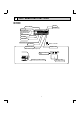
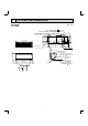
2 PART NAMES AND FUNCTIONS MS-A09WA MS-A12WA Air inlet Heat exchanger Front panel Panel Air cleaning filter (Anti-Allergy Enzyme Filter, Blue bellows type) Catechin air filter Air outlet Vertical vane Horizontal vane Remote controller Line flow fan Display section Operation section (When the front panel is opened) Operation Indicator lamp Emergency operation switch 3 Remote control receiving section
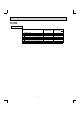
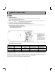
MS-A09WA MS-A12WA ACCESSORIES MS-A09/12WA Installation plate Installation plate fixing screw 4 × 25 mm Remote controller holder Fixing screw for 3.5 × 1.
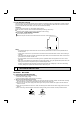
3 SPECIFICATION Model Indoor unit model External finish Power supply V, phase, Hz Max.-fuse size (time delay) / A Disconnect switch Min. circuit ampacity A Fan motor F.L.A Airflow COOL Low–Med.–High–Powerful Dry (Wet) CFM Moisture removal pt./h Sound level dB(A) Low–Med.–High–Powerful Cond. drain connection O.D. in. W Dimensions D in. H Weight Ib. Remote controller Control voltage (by built-in transformer) MS-A09WA MS-A09WA MS-A12WA MS-A12WA White 115, 1, 60 15 1.2 0.
OUTLINES AND DIMENSIONS Unit : inch MS-A09WA MS-A12WA Conduit plate(MS-A•WA- is excluded.) 7/16x13/16 Oblong hole Indoor unit 8-7/8 7/8 hole 7/8 6-1/8 2-3/16 6-1/8 13-3/16 1-3/4 12-5/8 3/16 11-3/4 24-9/16 Liquid line Gas line Insulation 1/4 19-11/16 3/8 16-15/16 1-3/8 O.D 3/4 I.D Drain hose 5/8 (Connected part O.
5 WIRING DIAGRAM MS-A09WA MS-A12WA 6 REFRIGERANT SYSTEM DIAGRAM MS-A09WA MS-A12WA Unit : inch Refrigerant pipe 3/8 (MS-A09) 1/2 (MS-A12) (with heat insulator) Indoor heat exchanger Indoor coil thermistor RT12 Flared connection Room temperature thermistor RT11 Flared connection Refrigerant flow in cooling 7 Refrigerant pipe 1/4 (with heat insulator)
7 SERVICE FUNCTIONS MS-A09WA MS-A12WA 7-1. TIMER SHORT MODE For service, set time can be shortened by short circuit of JPG and JPS the electronic control P.C. board. The time will be shortened as follows. (Refer to 8-7.) Set time : 1-minute 1-second Set time : 3-minute 3-second (It takes 3 minutes for the compressor to start operation. However, the starting time is shortened by short circuit-of JPG and JPS.) 7-2. P.C.
7-3. AUTO RESTART FUNCTION When the indoor unit is controlled with the remote controller, the operation mode, the set temperature, and the fan speed are memorized by the indoor electronic control P.C. board. The “AUTO RESTART FUNCTION” sets to work the moment power has restored after power failure. Then, the unit will restart automatically. Operation If the main power has been cut, the operation settings remain. After the power is restored, the unit restarts automatically according to the memory.
3. Troubleshooting procedure 1) First, check if the OPERATION INDICATOR lamp on the indoor unit is flashing on and off to indicate an abnormality. To make sure, check how many times the abnormality indication is flashing on and off before starting service work. 2) Before servicing check that the connector and terminal are connected properly. 3) When the electronic control P.C. board seems to be defective, check the copper foil pattern for disconnection and the components for bursting and discoloration.
8-2. FAILURE MODE RECALL FUNCTION Outline of the function This air conditioner can memorize the abnormal condition which has occurred once. Even though LED indication listed on the troubleshooting check table (8-4.) disappears, the memorized failure details can be recalled. 1. Flow chart of failure mode recall function for the indoor/outdoor unit Operational procedure The cause of abnormality cannot be found because the abnormality doesn't recur.
2. Indoor unit failure mode table Left lamp of OPERATION INDICATOR lamp Not lighted Abnormal point (Failure mode) Normal Condition Correspondence — The room temperature thermistor short or 1-time flash every Room temperature open circuit is detected every 8 seconds dur0.5-second thermistor ing operation. 2-time flash Indoor coil therThe indoor coil thermistor short or open circuit 2.5-second OFF mistor is detected every 8 seconds during operation.
8-3. INSTRUCTION OF TROUBLESHOOTING Start Indoor unit doesn't receive the signal from remote controller. Indoor unit operates. Outdoor unit doesn't operate. OPERATION INDICATOR lamp on the indoor unit is flashing on and off. Outdoor unit operates only in Test Run operation. Outdoor unit doesn't operate even in Test Run operation. Indoor unit operates, when EMERGENCY OPERATION switch is pressed. Indoor unit doesn't operate, when EMERGENCY OPERATION switch is pressed.
8-4. TROUBLESHOOTING CHECK TABLE Before taking measures, make sure that the symptom reappears for accurate troubleshooting. When the indoor unit has started operation and detected an abnormality of the following condition (the first detection after the power ON), the indoor fan motor turns OFF and OPERATION INDICATOR lamp flashes. OPERATION INDICATOR Lighted Blinking Not lighted No.
8-5. TROUBLE CRITERION OF MAIN PARTS MS-A09WA MS-A12WA Part name Room temperature thermistor (RT11) Check method and criterion Measure the resistance with a tester. (Part temperature 50 ~ 86°F) Indoor coil thermistor (RT12) Refer to 8-7. "Test point diagram and voltage", the chart of thermistor. Indoor fan motor (MF) Check 8-6. . Measure the resistance between the terminals with a tester.
8-6. TROUBLESHOOTING FLOW A Check of indoor fan motor The indoor fan motor error has occurred, and the indoor fan doesn't operate. Turn OFF the power supply. Pay careful attention to the high voltage on the fan motor connector CN211. Is there any foreign matter that interferes the rotation of the line flow fan? Turn ON the power supply, wait 5 seconds or more, and then press EMERGENCY OPERATION switch. Measure the supply voltage as follows within 12 seconds after EMERGENCY OPERATION switch is pressed.
B Check of remote controller and indoor electronic control P.C. board Check if the remote controller is exclusive for this air conditioner. Press OPERATE/STOP (ON/OFF) button on the remote controller. Is LCD display on the remote controller visible? Yes No (Not clear) Replace the batteries. (Refer to 8-1.4.) Remove the batteries, then set them back and press RESET button. (Refer to 8-1.4.) Check if the unit operates with the remote controller.
C Check of indoor electronic control P.C. board and indoor fan motor Turn OFF the power supply. Remove indoor fan motor connector CN211 and vane motor connector CN151 from the indoor electronic control P.C. board and turn ON the power supply. Measure the resistance between CN211 and of the indoor fan motor connector. Short/open circuit: Replace the indoor fan motor. Measure the resistance of the horizontal vane motor coil. (Refer to 8-5.
D Electromagnetic noise enters into TV sets or radios Is the unit grounded? No Ground the unit. Yes Is the distance between the antennas and the indoor unit within 9.91 ft., or is the distance between the antennas and the outdoor unit within 9.91 ft.? Yes Extend the distance between the antennas and the indoor unit, and/or the antennas and the outdoor unit. Yes Extend the distance between the TV sets and/or radios and the indoor unit, or the TV sets or radios and the outdoor unit.
8-7. TEST POINT DIAGRAM AND VOLTAGE MS-A09WA MS-A12WA Indoor electronic control P.C. board Power supply input 115 VAC } Varistor (NR11) Fuse (F11) 250 V 3.15 A Resistor (R111) Indoor fan motor (CN211) 162 VDC (-) Fiducial terminal of cathode side on measuring high-voltage DC 15 VDC (+)3-6 VDC (+)0 or 15 VDC Release of Auto restart function Solder the Jumper wire to JR07 (Refer to 7-3.
9 DISASSEMBLY INSTRUCTIONS <"Terminal with locking mechanism" Detaching points> The terminal which has the locking mechanism can be detached as shown below. There are two types (refer to (1) and (2)) of the terminal with locking mechanism. The terminal without locking mechanism can be detached by pulling it out. Check the shape of the terminal before detaching. (1) Slide the sleeve and check if there is a locking lever or not. (2) The terminal with this connector has the locking mechanism.
OPERATING PROCEDURE PHOTOS 2. Removing the electronic control P.C. board, the power monitor receiver P.C. board, SW P.C. board and the terminal block (1) Remove the horizontal vane, the panel (refer to 1.) and the corner box. (2) Remove the screw of the conduit cover, and conduit cover. (Photo 2 or Photo 3) (3) Remove the indoor/outdoor connecting wire. (4) Remove the switch holder from the electrical cover. (Photo 4) (5) Remove the screw of the electrical cover, and then the electrical cover.
OPERATING PROCEDURE PHOTOS 4. Removing the horizontal vane motor unit Photo 7 (1) Remove the horizontal vane and the panel. (Refer to 1.) (2) Remove the screws of the horizontal vane motor unit, and pull out the horizontal vane motor unit. (Photo 7) (3) Disconnect the connector from the horizontal vane motor unit. 5. Removing the indoor fan motor and the line flow fan (1) Remove the horizontal vane, the panel (Refer to 1.) and the corner box. (2) Remove the switch holder and the electrical box.
10 PARTS LIST 10-1. PARTS LIST (non-RoHS compliant) MS-A09WA MS-A12WA 1. INDOOR UNIT STRUCTURAL PARTS 2. ACCESSORY AND REMOTE CONTROLLER 9 1 11 12 10 8 2 7 (See 10-1.5.) 3 4 5 6 1. INDOOR UNIT STRUCTURAL PARTS No. 1 2 3 4 5 6 7 8 9 10 Part No.
MS-A09WA MS-A12WA 3. INDOOR UNIT ELECTRICAL PARTS AND FUNCTIONAL PARTS 1 18 17 14 15 16 2 3 4 5 6 11 10 9 8 7 No. 1 2 3 4 5 6 Part No. Part name Symbol in Wiring Diagram E02 751 509 E02 001 504 E02 897 702 E02 A49 235 E02 897 303 E02 913 040 12 Q'ty/unit MS-A09WA BEARING MOUNT 1 SLEEVE BEARING 1 DRAIN HOSE 1 NOZZLE ASSEMBLY 1 VANE MOTOR UNIT (HORIZONTAL) MV 1 HORIZONTAL VANE 1 POWER MONITOR RECEIVER P.C.
MS-A09WA MS-A12WA 4. INDOOR UNIT HEAT EXCHANGER 1 2 3 No. Part No. Part name Symbol in Wiring Diagram E02 A49 620 INDOOR HEAT EXCHANGER E02 A50 620 E02 151 666 2 UNION (GAS) E02 155 666 E02 151 667 3 UNION (LIQUID) Q'ty/unit MS-A09WA MS-A12WA Remarks 1 1 1 1 1 1 1 ø3/8 ø1/2 ø1/4 5. AIR CLEANING FILTER (ANTI-ALLERGY ENZYME FILTER) ● AIR CLEANING FILTER removes fine dust of 0.01 micron from air by means of static electricity. ● Normal life of AIR CLEANING FILTER is 1 year.
10-2. RoHS PARTS LIST (RoHS compliant) MS-A09WA MS-A12WA 1. INDOOR UNIT STRUCTURAL PARTS 2. ACCESSORY AND REMOTE CONTROLLER 9 1 12 11 10 8 2 7 (See 10-2.5.) 3 4 5 6 No. RoHS 1. INDOOR UNIT STRUCTURAL PARTS Part No.
MS-A09WA MS-A12WA 3. INDOOR UNIT ELECTRICAL PARTS AND FUNCTIONAL PARTS 1 19 16 17 18 15 2 3 4 5 6 12 11 7 10 No. RoHS 8 1 2 3 4 5 6 G G G G G G Part No. Part name 9 Symbol in Wiring Diagram E12 751 509 E12 001 504 E12 897 702 E12 A49 235 E12 897 303 E12 913 040 13 Q'ty/unit MS-A09WA MS-A12WA - 1 - 1 1 1 1 1 1 1 1 1 1 1 1 1 1 1 1 1 1 1 1 1 1 1 1 1 BEARING MOUNT SLEEVE BEARING DRAIN HOSE NOZZLE ASSEMBLY VANE MOTOR UNIT (HORIZONTAL) MV HORIZONTAL VANE POWER MONITOR RECEIVER P.C.
MS-A09WA MS-A12WA 4. INDOOR UNIT HEAT EXCHANGER 1 2 No. 1 2 3 RoHS 3 G G G G G Part No. Part name Symbol in Wiring Diagram E12 A49 620 INDOOR HEAT EXCHANGER E12 A50 620 E12 151 666 UNION (GAS) E12 155 666 E12 151 667 UNION (LIQUID) Q'ty/unit MS-A09WA MS-A12WA - 1 - 1 1 1 1 1 1 1 1 1 1 1 1 1 Remarks ø3/8 ø1/2 ø1/4 5. AIR CLEANING FILTER (ANTI-ALLERGY ENZYME FILTER) ● AIR CLEANING FILTER removes fine dust of 0.01 micron from air by means of static electricity.
11 MICROPROCESSOR CONTROL MS-A09WA MS-A12WA WIRELESS REMOTE CONTROLLER Signal transmitting section Operation display section ON/OFF (operate/ stop) button VANE button (Horizontal vane button) Fan speed control button Temperature buttons Off-timer button Operation select button ECONO COOL button Indication of remote controller model is on back On-timer button TIME set buttons Forward button Backward button POWERFUL button CLOCK set button RESET button NOTE Use the remote controller provided with
11-1. COOL ( ) OPERATION (1) Press OPERATE/STOP (ON/OFF) button. OPERATION INDICATOR lamp of the indoor unit turns on with a beep tone. (2) Select COOL mode with OPERATION SELECT button. (3) Press TEMPERATURE buttons (TOO WARM or TOO COOL button) to select the desired temperature. The setting range is 61 ~ 88°F. 1. Coil forest prevention When the temperature of indoor heat exchanger becomes too low, the coil frost prevention mode works. The indoor fan operates at the set speed and the compressor stops.
(5) TEMPERATURE buttons In “I FEEL CONTROL” ( ) mode, set temperature is decided by the microprocessor based on the room temperature. In addition, set temperature can be controlled by TOO WARM or TOO COOL buttons when you feel too cool or too warm. Each time the TOO WARM or TOO COOL button is pressed, the indoor unit receives the signal and emits a beep tone.
(8) To change the airflow direction not to blow directly onto your body. To change the airflow direction Pressing and holding VANE CONTROL button for 2 seconds or more, the horizontal vane reverses and moves horizontal position. Horizontal position When to use this function? COOL/DRY Use this function if you don’t want the air from the indoor unit to blow directly onto your body. • Depending on the shape of the room, the air may blow directly onto your body.
11-6. TIMER OPERATION 1. How to set the timer (1) Press OPERATE/STOP (ON/OFF) button to start the air conditioner. (2) Check that the current time is set correctly. NOTE : Timer operation will not work without setting the current time. Initially “0:00” blinks at the current time display of TIME MONITOR, so set the current time correctly with CLOCK SET button. How to set the current time (1) Press the CLOCK set button. (2) Press the TIME SET buttons ( and ) to set the current time.
11-7. EMERGENCY/TEST OPERATION In case of test run operation or emergency operation, use EMERGENCY OPERATION switch on the front of the indoor unit. Emergency operation is available when the remote controller is missing, has failed or the batteries of the remote controller run down. The unit will start and OPERATION INDICATOR lamp will light. The first 30 minutes of operation is the test run operation. This operation is for servicing.
TM HEAD OFFICE: TOKYO BLDG., 2-7-3, MARUNOUCHI, CHIYODA-KU, TOKYO 100-8310, JAPAN Copyright 2006 MITSUBISHI ELECTRIC ENGINEERING CO.,LTD Distributed in Oct. 2008. No. OB448 REVISED EDITION-C 5 Distributed in Jun. 2008. No. OB448 REVISED EDITION-B 6 Distributed in May 2007. No. OB448 REVISED EDITION-A 7 Distributed in Mar. 2006. No. OB448 7 Made in Japan New publication, effective Oct. 2008 Specifications subject to change without notice.