P-SERIES AND M-SERIES APPLICATION NOTES P-SERIES A CONTROL WIRING DIAGRAM....................................................................................................................AN-1 MS-A WIRING DIAGRAM.................................................................................................................................................AN-3 MSY-MSZ WIRING DIAGRAM...............................................................................................................................
Application Note 1001: P-Series A Control Wiring Diagram ©2012 Mitsubishi Electric US, Inc. Due to continuing improvement, above specification may be subject to change without notice.
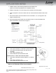
Indoor unit power is supplied from the outdoor unit. *Use of a disconnect at the indoor unit (part# TAZ-MS303) may be required in your jurisdiction. Use AWG14-3 600 VAC rated copper wiring between outdoor unit and indoor unit for high voltage and control circuits. P-Series units in a CITY MULTI application may only be grouped with P-Series units. Refer to the PAR-21MAA-E technical manual for grouping information. Figure 1 and Figure 2 illustrate available connection patterns. Figure 1.
Application Note 1002: MS-A Wiring Diagram ©2012 Mitsubishi Electric US, Inc. Due to continuing improvement, above specification may be subject to change without notice.
1. All MS-A indoor units must be powered from the outdoor unit. (Indoor unit cannot be powered from a separate source) 2. Outdoor unit power is 115 VAC using a two-conductor wire with ground. 3. Indoor unit power is from the outdoor unit from a terminal block marked to the indoor unit. 4. Connect the indoor unit to the outdoor unit on terminals L1, N, 2, and ground. Use copper conductors only. 5.
Application Note 1003: MSY-MSZ Wiring Diagram ©2012 Mitsubishi Electric US, Inc. Due to continuing improvement, above specification may be subject to change without notice.
1. All MSY/MSZ indoor units must be powered from the outdoor unit. (Indoor unit cannot be powered from a separate source) 2. Outdoor unit power is 208/230 VAC using a two-conductor wire with ground. 3. Indoor unit power is supplied from the outdoor unit from a terminal block marked S1, S2, S3. 4. Connect the indoor unit to the outdoor unit on terminals S1, S2, S3 and ground. Use copper conductors only. 5.
Application Note 1004: MXZ-2A20NA Wiring Diagram ©2012 Mitsubishi Electric US, Inc. Due to continuing improvement, above specification may be subject to change without notice.
1. All MSZ indoor units must be powered from the outdoor unit. (Indoor unit cannot be powered from a separate source). 2. MXZ outdoor unit power is 208/230 VAC circuit using a two-conductor wire with ground. 3. Each indoor unit is powered from the outdoor unit from a terminal blocked marked to the specific indoor unit. 4. Connect the indoor unit to the outdoor unit on terminals S1, S2, S3 and ground. Use copper conductors only. 5.
CONNECTING WIRES AND CONNECTING GROUND WIRE Use a solid conductor or stranded conductor AWG14. Use doubled insulated copper wire with 300 volt insulation. Use copper conductors only. Follow national and local electrical code. POWER SUPPLY CABLE AND GROUND WIRE Use solid or stranded conductor AWG12** or AWG14 wire. Use copper conductors only. Follow national and local electrical code. Note: All wiring shall comply with NEC and local electrical codes.
Application Note 1005: MXZ-3A30NA Wiring ©2012 Mitsubishi Electric US, Inc. Due to continuing improvement, above specification may be subject to change without notice.
1. All MSZ indoor units must be powered from the outdoor unit. (Indoor unit cannot be powered from a separate source). 2. MXZ outdoor unit power is 208/230 VAC circuit using a two-conductor wire with ground. 3. Each indoor unit is powered from the outdoor unit from a terminal blocked marked to the specific indoor unit. 4. Connect the indoor unit to the outdoor unit on terminals S1, S2, S3 and ground. Use copper conductors only. 5.
CONNECTING WIRES AND CONNECTING GROUND WIRE Use a solid conductor or stranded conductor AWG14. Use doubled insulated copper wire with 300 volt insulation. Use copper conductors only. Follow national and local electrical code. POWER SUPPLY CABLE AND GROUND WIRE Use solid or stranded conductor AWG12** or AWG14 wire. Use copper conductors only. Follow national and local electrical code. Note: All wiring shall comply with NEC and local electrical codes.
Application Note 1006: Low Temperature Heating Chart ©2012 Mitsubishi Electric US, Inc. Due to continuing improvement, above specification may be subject to change without notice.
Heat Pump Capacities Model Number 55° F 45° F 35° F 25° F 15° F 5° F 0° F 12,700 15,800 21,000 23,900 27,000 11,200 14,000 18,500 21,300 23,900 9,600 12,000 15,900 18,400 20,500 8,200 10,200 13,500 15,800 17,400 6,700 8,400 11,100 12,700 14,300 5,575 6,900 8,525 8,400 11,125 5,012 5,975 7,287 7,000 9,537 22,000 31,150 22,000 27,880 19,000 24,610 16,500 21,340 14,000 18,070 11,500 14,880 10,250 13,247 20,000 28,000 34,000 38,000 48,000 18,600 25,360 31,400 36,200 44,000 16,800 22,020
Application Note 1007: P-Series Twinning Wiring ©2012 Mitsubishi Electric US, Inc. Due to continuing improvement, above specification may be subject to change without notice.
1. Only 24,000 and 36,000 BTU units can be twinned. 2. The two indoor units must equal the capacity of the outdoor unit when added together. 3. Indoor units must be in the same conditioned space since the two return air temperature sensors will be averaged for the space temperature control. 4. The indoor units must be powered from the outdoor unit in a daisy chain fashion as shown in Figure 1. Note: * A disconnect switch (part# TAZ-MS303) may be required by local code at the indoor unit.
Application Note 1008: MXZ4A36NA Wiring Diagram ©2012 Mitsubishi Electric US, Inc. Due to continuing improvement, above specification may be subject to change without notice.
1. All MXZ indoor units must be powered from the outdoor unit. (Indoor unit cannot be powered from a separate source) 2. MXZ outdoor unit is powered 208/230 VAC in a two-conductor wire with ground. 3. Each indoor unit is powered from the outdoor unit from a terminal block marked to indoor unit. 4. Connect the indoor unit to the outdoor unit on terminals S1, S2, S3 and ground. Use copper conductors only. 5.
CONNECTING WIRES AND CONNECTING GROUND WIRE Use a solid conductor AWG14 or stranded conductor AWG18, AWG16, or AWG14. Use doubled insulated copper wire with 300 volt insulation. Use copper conductors only. Follow national and local electrical code. POWER SUPPLY CABLE AND GROUND WIRE Use solid or stranded conductor AWG14 wire. Use copper conductors only. Follow national and local electrical code. Note: All wiring shall comply with local electrical codes.
Application Note 1009: SI-1730-230 Wiring Diagram ©2012 Mitsubishi Electric US, Inc. Due to continuing improvement, above specification may be subject to change without notice.
Figure 1 illustrates the SI-1730-230V Wiring Diagram for Mitsubishi Electric MiniSplit Systems. Figure 1. SI-1730 -230V Wiring Diagram August 2009 Application Note 1009 ©2012 Mitsubishi Electric US, Inc. Page |2 Due to continuing improvement, above specification may be subject to change without notice.
Application Note 1010: SI-3100-115 Wiring Diagram ©2012 Mitsubishi Electric US, Inc. Due to continuing improvement, above specification may be subject to change without notice.
Figure 1 illustrates the SI-3100-115V Wiring Diagram for Mitsubishi Electric MiniSplit Systems. Figure 1. SI-3100-115V Wiring Diagram August 2009 Application Note 1010 ©2012 Mitsubishi Electric US, Inc. Page |2 Due to continuing improvement, above specification may be subject to change without notice.
Application Note 1011: SI-3100-208/230 Wiring Diagram ©2012 Mitsubishi Electric US, Inc. Due to continuing improvement, above specification may be subject to change without notice.
Figure 1 illustrates the SI-3100-208/230V Wiring Diagram for Mitsubishi Electric Mini-Split Systems. Figure 1. SI-3100-230V Wiring Diagram August 2009 Application Note 1011 ©2012 Mitsubishi Electric US, Inc. Page |2 Due to continuing improvement, above specification may be subject to change without notice.
Application Note 1012: Drain Line Applications ©2012 Mitsubishi Electric US, Inc. Due to continuing improvement, above specification may be subject to change without notice.
Use PVC piping for the drain line. When connecting the PVC piping, use adhesive to attach the supplied drain socket. Ensure that the drain line (pipe) is properly routed through the wall hole and inclined downwards (away from the indoor unit) as shown in Figure 1. The end of the drain line (pipe) must be lower than the drain outlet of the indoor unit. Ensure that there are no peaks and valleys in the run of the drain line that may cause trapped drainage.
Application Note 1013: Rated Capacity vs. Maximum Capacity ©2012 Mitsubishi Electric US, Inc. Due to continuing improvement, above specification may be subject to change without notice.
“Rated Capacity” is the system output capacity observed at standard AHRI rated testing conditions (47°F, and 17°F outdoor for heating). AHRI testing, performed to AHRI-210/240, requires the compressors to be run at a constant speed (60Hz) due to testing limitations. Any advantage gained by variable speed equipment is not exhibited in the test results. The test result values are listed in the AHRI Directory of Certified Product Performance, which is accessible through the AHRI website.
Application Note 1014: M-Series Dry Mode Description ©2012 Mitsubishi Electric US, Inc. Due to continuing improvement, above specification may be subject to change without notice.
Mitsubishi Electric/HVAC Division offers air conditioning equipment specifically for thermal comfort conditioning. While the units are designed for cooling and in the case of Heat Pumps for heating and not for humidity control there is a function to reduce the latent content in the air. Dry Mode is the operating mode for Mr. Slim and CITY MULTI indoor units used to reduce the moisture content of the air in the conditioned space served by the indoor unit – without significantly reducing the room temperature.
The relationship between the room temperature and the set temperature in Dry Mode is shown in Figure 1. Figure 1. The relationship between room temperature and set temperature Dry Mode uses the same coil frost prevention (defrost) as the Cool Mode to eliminate ice on the coil. July 2009 Application Note 1014 ©2012 Mitsubishi Electric US, Inc. Page |3 Due to continuing improvement, above specification may be subject to change without notice.
Application Note 1015: M&P-Series Air Outlet Coverage Range ©2012 Mitsubishi Electric US, Inc. Due to continuing improvement, above specification may be subject to change without notice.
Table 1. Air Outlet Coverage Range for MSZ-A & MSY-A Table 2. Air Outlet Coverage Range for MSZ-FD Table 3. Air Outlet Coverage Range for MSZ-D The air coverage range is the figure up to the position where the air speed is 1 ft/sec., when air is blown out horizontally from the unit properly at the High speed position. The coverage range should be used only as a general guideline since it varies according to the size of the room and furniture arranged inside the room.
Table 4. Air Outlet Coverage Range for P-Series The air coverage range is the value up to the position where the air speed is 0.8 ft/sec. when air is blown out horizontally from the unit at the Hi notch position. The coverage range should be used only as a general guideline since it varies according to the size of the room and the furniture inside the room. July 2009 Application Note 1015 ©2012 Mitsubishi Electric US, Inc.
Application Note 1016: M&P-Series Remote Access ©2012 Mitsubishi Electric US, Inc. Due to continuing improvement, above specification may be subject to change without notice.
The Mr. Slim® product line has the capability to be controlled remotely by using the CITY MULTI® Centralized Controllers (AG-150/GB-50/GB-24), TG-2000 or by using an external automation system (Building Management System) using either LonWorks® or BACnet® (Building Automation and Control Networks) .
is to be used for each indoor unit with connected outdoor unit. The MAC-399IF can only be used with the inverter models of the M-Series (MXZ/MSY/MSZ). Note: The MAC-399IF M-NET converter cannot be used together with the MAC-397IF hard wire MA controller adapter on the same unit. If connection to the Centralized Controller and a hard wired remote controller is needed, use the ME controller for connection to the M-NET. The Mr.
M-Series When the M-Series units are to be integrated into the CITY MULTI® network with the Centralized Controllers the following components are needed: • MAC-399IF – M-NET converter (per indoor unit) • AG-150/GB-50/GB-24 – Centralized Controller When the M-Series units are to be integrated into the CITY MULTI® network with TG2000 the following components are needed: • MAC-399IF – M-NET converter (per indoor unit) • AG-150/GB-50 – Centralized Controller • TG-2000 software • Dedicated PC – Runs TG-2000 softw
Application Note 1017: M-Series Cooling Charts ©2012 Mitsubishi Electric US, Inc. Due to continuing improvement, above specification may be subject to change without notice.
7-3. Condensing pressure Data is based on the condition of indoor humidity 50%. Air flow should be set at High. A point on the curve shows the reference point. MU-A09WA MU-A12WA July 2009 Application Note 1017 ©2012 Mitsubishi Electric US, Inc. Page |2 Due to continuing improvement, above specification may be subject to change without notice.
Cooling Data is based on the condition of indoor humidity 50%. Air flow should be set to High speed. MUZ-A09NA MUZ-A09NA-U1 MUZ-A09NA-1 MUZ-A09NA-U2 July 2009 Application Note 1017 ©2012 Mitsubishi Electric US, Inc. Page |3 Due to continuing improvement, above specification may be subject to change without notice.
Cooling Data is based on the condition of indoor humidity 50%. Air flow should be set to set to High speed. MUZ-FD09NA MUZ-A12NA July 2009 Application Note 1017 ©2012 Mitsubishi Electric US, Inc. Page |4 Due to continuing improvement, above specification may be subject to change without notice.
Cooling Data is based on the condition of indoor humidity 50%. Air flow should be set to set to High speed. MUZ-FD12NA MUZ-A15NA MUY-A15NA July 2009 Application Note 1017 ©2012 Mitsubishi Electric US, Inc. Page |5 Due to continuing improvement, above specification may be subject to change without notice.
Cooling Data is based on the condition of indoor humidity 50%. Air flow should be set to set to High speed. MUZ-A17NA MUY-A17NA MUZ-A24NA MUY-A24NA July 2009 Application Note 1017 ©2012 Mitsubishi Electric US, Inc. Page |6 Due to continuing improvement, above specification may be subject to change without notice.
Cooling Data is based on the condition of indoor humidity 50%. Air flow should be set to set to High speed. MUZ-GA24NA MUY-GA24NA MUY-D30NA July 2009 Application Note 1017 ©2012 Mitsubishi Electric US, Inc. Page |7 Due to continuing improvement, above specification may be subject to change without notice.
Cooling Data is based on the condition of indoor humidity 50%. Air flow should be set to set to High speed. MUZ-D30NA MUY-D36NA July 2009 Application Note 1017 ©2012 Mitsubishi Electric US, Inc. Page |8 Due to continuing improvement, above specification may be subject to change without notice.
Cooling Data is based on the condition of indoor humidity 50%. Air flow should be set to set to High speed. MUZ-D36NA Heating Data is based on the condition of outdoor humidity 75%. Air flow should be set to High speed. Data is for heating operation without any frost. MUZ-A09NA MUZ-A09NA-U1 July 2009 Application Note 1017 ©2012 Mitsubishi Electric US, Inc. Page |9 Due to continuing improvement, above specification may be subject to change without notice.
Heating Data is based on the condition of outdoor humidity 75%. Air flow should be set to High speed. Data is for heating operation without any frost. MUZ-A09NA-1 MUZ-A09NA-U2 MUZ-FD09NA July 2009 Application Note 1017 ©2012 Mitsubishi Electric US, Inc. P a g e | 10 Due to continuing improvement, above specification may be subject to change without notice.
Heating Data is based on the condition of outdoor humidity 75%. Air flow should be set to High speed. Data is for heating operation without any frost. MUZ-A12NA MUZ-FD12NA July 2009 Application Note 1017 ©2012 Mitsubishi Electric US, Inc. P a g e | 11 Due to continuing improvement, above specification may be subject to change without notice.
Heating Data is based on the condition of outdoor humidity 75%. Air flow should be set to High speed. Data is for heating operation without any frost. MUZ-A15NA MUZ-A17NA July 2009 Application Note 1017 ©2012 Mitsubishi Electric US, Inc. P a g e | 12 Due to continuing improvement, above specification may be subject to change without notice.
Heating Data is based on the condition of outdoor humidity 75%. Air flow should be set to High speed. Data is for heating operation without any frost. MUZ-A24NA MU-GA24NA July 2009 Application Note 1017 ©2012 Mitsubishi Electric US, Inc. P a g e | 13 Due to continuing improvement, above specification may be subject to change without notice.
Application Note 1018: Mr. Slim Cooling Capacity Correction Factors ©2012 Mitsubishi Electric US, Inc. Due to continuing improvement, above specification may be subject to change without notice.
Refrigerant piping length (one way : ft.) 25 (std.) 40 65 Model MS-A09WA MS-A12WA 1.0 0.954 0.878 Refrigerant piping length (one way : ft.) 25 (std.) 40 65 100 Model MSZ-A09/12/15/17NA MSY-A15/17NA 1.0 0.954 0.878 MSZ-A24NA MSY-A24NA 1.0 0.95 0.878 Refrigerant piping length (one way : ft.) 25 (std.) 40 65 Model MUZ-FD09NA MUY-FD12NA Model MUZ-D30NA MUZ-D36NA MUY-D30NA MUY-D36NA 0.713 1.0 0.954 0.878 Refrigerant piping length (one way : ft.) 25 (std.) 40 65 100 1.0 0.95 0.
Application Note 1019: M-Series Cooling Performance Data ©2012 Mitsubishi Electric US, Inc. Due to continuing improvement, above specification may be subject to change without notice.
July 2009 Application Note 1019 ©2012 Mitsubishi Electric US, Inc. Page |2 Due to continuing improvement, above specification may be subject to change without notice.
July 2009 Application Note 1019 ©2012 Mitsubishi Electric US, Inc. Page |3 Due to continuing improvement, above specification may be subject to change without notice.
Application Note 1020: M Series Outdoor Unit Clearances ©2012 Mitsubishi Electric US, Inc. Due to continuing improvement, above specification may be subject to change without notice.
July 2009 Application Note 1020 ©2012 Mitsubishi Electric US, Inc. Page |2 Due to continuing improvement, above specification may be subject to change without notice.
July 2009 Application Note 1020 ©2012 Mitsubishi Electric US, Inc. Page |3 Due to continuing improvement, above specification may be subject to change without notice.
July 2009 Application Note 1020 ©2012 Mitsubishi Electric US, Inc. Page |4 Due to continuing improvement, above specification may be subject to change without notice.
July 2009 Application Note 1020 ©2012 Mitsubishi Electric US, Inc. Page |5 Due to continuing improvement, above specification may be subject to change without notice.
July 2009 Application Note 1020 ©2012 Mitsubishi Electric US, Inc. Page |6 Due to continuing improvement, above specification may be subject to change without notice.
July 2009 Application Note 1020 ©2012 Mitsubishi Electric US, Inc. Page |7 Due to continuing improvement, above specification may be subject to change without notice.
July 2009 Application Note 1020 ©2012 Mitsubishi Electric US, Inc. Page |8 Due to continuing improvement, above specification may be subject to change without notice.
July 2009 Application Note 1020 ©2012 Mitsubishi Electric US, Inc. Page |9 Due to continuing improvement, above specification may be subject to change without notice.
Application Note 1021: M&P Series High Altitude Applications ©2012 Mitsubishi Electric US, Inc. Due to continuing improvement, above specification may be subject to change without notice.
When air conditioners and heat pumps are installed in areas above sea level, capacity is reduced due to decreased air density. Equipment size must be increased to meet the load requirements. The following correction factors apply to CITY MULTI and Mr. Slim air conditioners and heat pumps for both heating and cooling operation. The indoor and outdoor units need to be sized based on the capacity reduction due to the decreased air density.
Adjusting equipment size for high-altitude applications is not supported by Design Tool software, so correction factors must be performed manually. No other adjustments are necessary in the system design and application. August 2012 Application Note 1021 ©2012 Mitsubishi Electric US, Inc. Page |3 Due to continuing improvement, above specification may be subject to change without notice.
Application Note 1022: Regarding Refrigerant Accessories ©2012 Mitsubishi Electric US, Inc. Due to continuing improvement, above specification may be subject to change without notice.
August 21, 2006 MEMO: Refrigerant Accessories Please be advised that we do not recommend the following accessories on our ductless air conditioners or heat pump units. Filter Driers: Our units are made in the factory under clean conditions and are brazed using dry nitrogen. They are charged with clean oil and new refrigerant. When the line sets are attached using flare connections the copper is clean. Under clean conditions filter driers are not necessary and will only cause pressure drops in the system.
Application Note 1023: P-Series Indoor Fan Cycle Off ©2012 Mitsubishi Electric US, Inc. Due to continuing improvement, above specification may be subject to change without notice.
Figure 1: R410A P-Series Indoor Fan Cycle Off in Heat or Cool Mode with PAR-21MAA Controller Here are the 5 Steps to setting up the PAR-21MAA Controller displayed in Figure 1: 1. Press the airflow up/down (J) button and test (B) button at the same time for two seconds 2. Wait for a few seconds until the small dashes start to flash then press the clock (C) buttons to change refrigerant address to 00 then press the clock on/off (D) button then the clock (C) buttons to change unit number to 01 3.
Application Note 1024: Supplemental Heat Control ©2012 Mitsubishi Electric US, Inc. Due to continuing improvement, above specification may be subject to change without notice.
The P-Series, SEZ and SLZ indoor units, when installed with MXZ, PUZ or SUZ heat pump outdoor units, can interface and enable supplemental and auxiliary heat sources using an indoor board connector (CN-24 or CN-152, depending on indoor unit). For indoor units connected to PUY outdoor units, external heat control does not function. (Please note that at this time M-Series indoor units (MS/MSZ/MFZ) do NOT support any supplemental heat control or interface capabilities.
Supplemental Heat Control via CN-24 for PLA, PCA and SLZ Indoor Units CN-24 controls are indicated in Figure 1and require no setup at the remote controller. This function is only available in heating operation. Figure 1. CN-24 controls Figure 2 illustrates a typical wiring diagram for PLA, PCA and SLZ indoor units using CN-24: Figure 2.
Figure 3. CN4YControls Selecting setting #2 for Setup Function 123 on MHK1 (or Mode 23 on PAR-21MAAU) allows Setup Function 125 on MHK1 (or Mode 25 on PAR21MAA) and CN4Y to be used to control the indoor unit fan during defrost and error conditions as shown in Figure 3. Table 2 and 3 lists the settings to be used to achieve the fan operation desired. Table 2.
Figure 4 illustrates a typical wiring diagram for PEA(D) and SEZ indoor units using CN24: Figure 4. Wiring Diagram for PEA(D) and SEZ indoor units Supplemental Heat Control via CN-152 for PKA Wall-mounted Indoor Units CN-152 controls are indicated in Figure 5 and require no setup at remote controller. This function is only available in heating operation. Figure 5. CN-152 Controls Figure 6 illustrates a typical wiring diagram for PKA wall-mounted indoor unit using CN152. Yellow CN-152 Brown Figure 6.
Wiring restrictions for ALL field wiring in all of the above diagrams: Keep the length of the cable connecting to the circuit board of the indoor unit shorter than 32 ft. (10 meters). Wire size should be 22 ~ 16 AWG (0.5 mm2 ~ 1.25 mm2) depending on length and conditions. All wiring should conform to all local codes and the National Electric Code where applicable. August 2012 Application Note 1024 ©2012 Mitsubishi Electric US, Inc.
Application Note 1025: No Simultaneous Heating and Cooling with MXZ ©2013 Mitsubishi Electric US, Inc. Due to continuing improvement, above specification may be subject to change without notice.
Multi-zone (MXZ) heat pump systems can connect two or more indoor units with one outdoor unit. Be advised that multi-zone systems with model numbers that begin with MXZ do not support simultaneous heating and cooling. All indoor units on these type models must all be in the same mode at the same time: either cooling or heating. The entire system will have a mode; individual indoor units set to the opposite mode will be in standby.
mode, having auto mode enabled on the connected indoor units does not guarantee that the system will switch modes when an indoor unit switches modes. Therefore, auto mode does not work as users expect on a multi-zone system, and is not recommended. Simultaneous Heating and Cooling For applications that require simultaneous heating and cooling, Mitsubishi Electric Cooling & Heating offers two options: 1. For smaller applications, multiple one-to-one single-zone systems. 2.