OC247-E--1.qxp 04.8.11 4:25 PM Page 1 SPLIT-TYPE, AIR CONDITIONERS No. OC247 REVISED EDITION-E TECHNICAL & SERVICE MANUAL Models PU12EK PU18EK PU18EK1 PU24EK PU24EK1 PU24EK2 PU24EK3 PU30EK PU30EK1 PU30EK2 PU30EK3 PU36EK PU36EK1 PU36EK2 PU36EK3 PU42EK2 PU42EK21 PU42EK7 PU42EK71 PU42EK72 CONTENTS Outdoor unit 1. FEATURES ························································2 2. TECHNICAL CHANGE ······································3 3.
OC247-E--1.qxp 04.8.11 4:25 PM Page 2 Correction: “ 13. PARTS LIST ” has been modified on page 33 and 43. Page Revise point Model FUNCTIONAL PARTS No.12 CAPILLARY TUBE 33 FUNCTIONAL PARTS No.17 TRANSFORMER PU12EK FUNCTIONAL PARTS No.20 OUTDOOR CONTROLLER BOARD 43 FUNCTIONAL PARTS No.1 FAN MOTOR Incorrect Correct T7W 588 425 T7W E07 425 T7W 850 799 T7W A30 799 T7W 850 315 T7W E08 315 T7W A05 763 T7W 853 763 PU42EK7 PU42EK71 PU42EK72 1 FEATURES 1.
OC247-E--1.qxp 2 04.8.11 4:25 PM Page 3 TECHNICAL CHANGE (OC247 REVISED EDITION-A) Change of the service parts. Refer to “13. PARTS LIST” for the details. PU18EK PU24EK PU30EK PU36EK PU42EK2 ➔ ➔ ➔ ➔ ➔ PU18EK1 PU24EK1 PU30EK1 PU36EK1 PU42EK21 1. OUTDOOR CONTROLLER BOARD has been changed. 2. TRANSFORMER has been changed. PU18EK ➔ PU18EK1 • CONTACTOR has been changed. (OC247 REVISED EDITION-B) PU24EK1 ➔ PU24EK2 PU30EK1 ➔ PU30EK2 PU36EK1 ➔ PU36EK2 • COMPRESSOR has been changed.
OC247-E--1.qxp 3 04.8.11 4:25 PM Page 4 COMBINATION OF INDOOR AND OUTDOOR UNITS Outdoor unit PU Indoor unit 12 Models PL • AK Service manual No.
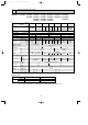
OC247-E--1.qxp 04.8.11 4:25 PM 5 Page 5 SPECIFICATIONS MODELS : PU12EK PU18EK PU24EK PU30EK PU18EK1 PU24EK1 PU30EK1 PU24EK2 PU30EK2 PU24EK3 PU30EK3 Model Item OUTDOOR UNIT MODELS External finish Power supply V, phase, Hz Max.fuse size (time delay) A Min.ampacity A Fan motor F.L.A. Model (type) Compressor R.L.A. L.R.A. Crankcase heater A(W) Refrigerant control dB Sound level W in. Dimensions D in. H in.
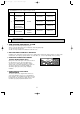
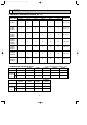
OC247-E--1.qxp 6 04.8.11 4:25 PM Page 6 DATA 1. ADDITIONAL REFRIGERANT CHARGE (R22 : oz) Piping length (one way) 130 ft 145 ft 160 ft 164 ft Factory charged — — — 4 lbs 14 oz 4 — — — 5 lbs 8 oz 2 4 6 8 9 9 lbs 15 oz 0 5 10 14 19 20 10 lbs 2 oz 0 5 10 14 19 20 10 lbs 9 oz PU42EK2 PU42EK21 0 5 10 14 19 20 12 lbs 9 oz PU42EK7 PU42EK71 PU42EK72 0 5 10 14 19 20 11 lbs 0 oz Service Ref.
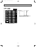
OC247-E--1.qxp 04.8.11 4:25 PM Page 7 3. NOISE CRITERION CURVES PU18EK PU18EK1 OCTAVE BAND SOUND PRESSURE LEVEL, dB re 0.0002 MICRO BAR LINE 90 80 70 NC-70 60 NC-60 50 NC-50 40 NC-40 30 NC-30 20 APPROXIMATE THRESHOLD OF HEARING FOR CONTINUOUS NOISE NC-20 10 63 PU24EK PU24EK1 PU24EK2 PU24EK3 OCTAVE BAND SOUND PRESSURE LEVEL, dB re 0.
OC247-E--1.qxp 04.8.11 4:25 PM Page 8 OCTAVE BAND SOUND PRESSURE LEVEL, dB re 0.0002 MICRO BAR PU42EK2 PU42EK7 PU42EK21 PU42EK71 PU42EK72 SPL(dB) 56 LINE 90 MICROPHONE 3.3ft 80 UNIT 3.
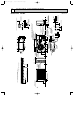
Handle for moving 3-3/4 For 10 units or less Rear piping hole 1/2 5-7/16 8 9/32 Side air intake Rear fresh air intake 40 11-5/8 1 Outlet guide installation hole Handle for moving 1-5/16 4 29/32 20-5/8 Drain hole 1-9/16 34-1/4 Drain hole 15/32 29/32 Oval holes (standard bolt M10) 20-5/8 11-7/8 Air out 1/2 1/2 36 Front opening 15/32 R 4 1/ 2-9/16 32 5/ 2-3/8 4-3/4 Standard bolt length Knock out holes for power line 1-1/16 (for N.E.
Handle for moving 3-3/4 4 For 10 units or less Rear piping hole 1/2 5-7/16 Rear fresh air intake Side air intake 8 40 1/4 11-5/8 Outlet guide installation hole 20-5/18 1-9/16 Drain hole Handle for moving 1 2 1 Air intake 17-3/18 34-1/4 Drain hole 1/2x7/8 Oval holes (standard bolt W3/8(M10) 20-5/8 11-7/8 Air outlet Air intake 14-1/4 1/2 15-7/8 1/2 36 Service panel Ground terminal Handle for moving 2-3/8 1/2 R 4 1/ Bottom piping hole 16 3/ 2-9/16 4-3/4 2-3/8 (for N.
5-7/16 Handle for moving 3-3/4 1/2 Rear piping hole For 10 units or less 12 40 Rear fresh air intake Side air intake 1 6 1/4 11-5/8 Air intake Outlet guide installation hole 1-9/16 Drain hole Handle for moving 1 2 23-1/16 13-9/16 20-5/8 2-3/8 20-5/8 3-1/4 34-1/4 Drain hole 2-1/2x7/8 Oval holes (standard bolt M10)W3/8(M10) 20-5/8 11-7/8 Air outlet Air intake 11/16 Handle for moving Ground terminal 2-3/8 1/2 2-U-shaped notched holes 1/2 4 1/ R 2-9/16 (for N.E.
Handle for moving 3-3/4 6 For 10 units or less Rear piping hole 1/2 5-7/16 12 Rear fresh air intake Side air intake 1/4 13-9/16 Outlet guide installation hole 1-9/16 Drain hole Handle for moving 1 20-5/8 2-3/8 20-5/8 7/8 38-3/16 Drain hole 2-1/2x7/8 Oval holes (standard bolt W3/8(M10) 20-5/8 13-7/8 Air outlet 2-3/8 2-U-shaped notched holes 1/2 Bottom piping hole 1-9/16 4-1/8 Handle for moving Ground terminal 1/2 Front right piping holesdetail figures Knock out hole for right
OC247-E--1.qxp 04.8.11 4:25 PM 8 Page 13 WIRING DIAGRAM MODEL : PU12EK SYMBOL PU18EK 1 NAME SYMBOL NAME SYMBOL NAME C COMPRESSOR CAPACITOR LD1 ~ LD8 LED TH3 OUTDOOR COIL THERMISTOR C3 FAN CAPACITOR MC COMPRESSOR X11 CRANKCASE HEATER RELAY CH CRANKCASE HEATER MF OUTDOOR FAN MOTOR (INNER THERMOSTAT) X12 COMPRESSOR RELAY CN3 CONNECTING WIRES INDOOR/OUTDOOR CONNECTOR O. B OUTDOOR CONTROLLER BOARD ZNR VARISTOR SW1, 2, 3
OC247-E--1.qxp 04.8.11 4:25 PM Page 14 MODELS : PU18EK SYMBOL NAME SYMBOL NAME SYMBOL NAME C COMPRESSOR CAPACITOR LD1 ~ LD8 LED TH3 OUTDOOR COIL THERMISTOR C3 FAN CAPACITOR MC COMPRESSOR X11 CRANKCASE HEATER RELAY CH CRANKCASE HEATER MF3 OUTDOOR FAN MOTOR (INNER THERMOSTAT) X12 COMPRESSOR RELAY CN3 CONNECTING WIRES INDOOR/OUTDOOR CONNECTOR O. B OUTDOOR CONTROLLER BOARD ZNR VARISTOR SW1, 2, 3
OC247-E--1.qxp 04.8.11 4:25 PM Page 15 MODELS : PU24EK PU30EK PU36EK PU42EK2 SYMBOL NAME SYMBOL NAME SYMBOL NAME C COMPRESSOR CAPACITOR LD1~LD8 LED TH3 OUTDOOR COIL THERMISTOR C3, 4 FAN CAPACITOR MC COMPRESSOR (INNER THERMOSTAT) X11 CRANKCASE HEATER RELAY CH CRANKCASE HEATER MF3, 4 OUTDOOR FAN MOTOR (INNER THERMOSTAT) X12 COMPRESSOR RELAY CN3 CONNECTING WIRES INDOOR/OUTDOOR CONNECTOR O. B OUTDOOR CONTROLLER BOARD ZNR
OC247-E--1.qxp 04.8.11 4:25 PM Page 16 MODELS : PU24EK1 PU30EK1 PU36EK1 PU42EK21 PU42EK7 PU24EK2 PU30EK2 PU36EK2 PU24EK3 PU30EK3 PU36EK3 SYMBOL NAME SYMBOL NAME SYMBOL NAME C COMPRESSOR CAPACITOR LD1~LD8 LED TH3 OUTDOOR COIL THERMISTOR C3, 4 FAN CAPACITOR MC COMPRESSOR (INNER THERMOSTAT) X11 CRANKCASE HEATER RELAY CH CRANKCASE HEATER MF1, 2 OUTDOOR FAN MOTOR (INNER THERMOSTAT) X12 COMPRESSOR RELAY CN3
OC247-E--1.qxp 04.8.11 4:25 PM Page 17 MODEL : PU42EK71 PU42EK72 NAME SYMBOL NAME SYMBOL NAME SYMBOL THERMISTOR FOR PIPE TEMPERATURE LD1~LD8 LED(CHECK, SERVICE) CN3 CONNECTOR TH3 (CONNECTING WIRES INDOOR/OUTDOOR) (32°F/15kΩ,77°F/5.4kΩ) MC CN4T CONNECTOR(TRANSFORMER) COMPRESSOR MOTOR (INNER THERMOSTAT) X11 AUXILIARY RELAY FOR CH CH CRANKCASE HEATER MF1, 2 FAN MOTOR (INNER THERMOSTAT) X12 AUXILIARY RELAY FOR MC C3, 4 RUN CAPACITOR FOR MF1,2 O.
OC247-E--1.qxp 9 04.8.
OC247-E--1.qxp 10 04.8.11 4:25 PM Page 19 MICROPROCESSOR CONTROL OUTDOOR MICROPROCESSOR CONTROL 1. Protection function (1) As soon as a reversed phase, an open phase, or a P. C. board trouble is sensed, the operation stops and the check code is displayed by LED on the outdoor controller board. (2) When a protection function such as high pressure switch and overcurrent relay works for the first time, the operation stops and restarts after 3-minute time delay mode.
OC247-E--1.qxp 04.8.11 4:25 PM Page 20 6. Fixed fan-output While the compressor is operating and the fan output step is indicated by LED, pushing SW2 fixes the fan output of that time. The fixed fan-output can be released when either of the following conditions is satisfied. 1 SW2 is pushed again. 2 SW3 setting is changed. 3 The compressor stops. 7.
OC247-E--1.qxp 04.8.11 4:25 PM 11 Page 21 TROUBLESHOOTING 1. SERVICE DATA INDICATION BY SWITCHES ON OUTDOOR CONTROLLER BOARD Setting dip switches SW2 and SW3 on the outdoor controller board enables LED to show the output state and check code. Output state is shown by LED lighting, and check code by blinking. SW1 : Turning SW1 ON clears the check code. If SW1 is turned ON while the check code is blinking , the indication changes to output state indication.
OC247-E--1.qxp 04.8.11 4:25 PM Page 22 1-1 Outdoor coil temperature To obtain data on the outdoor coil temperature, add the number of bits of lighting LEDs, and see the graph to find the temperature. ˚F 212 (Short 38 bits) 176 140 Temperature 104 68 32 -4 -40 (Open 219 bits) 0 50 100 150 200 255 Number of bits 1-2 Fan output step To obtain data on the fan output step, add the number of bits of lighting LEDs, and see the graph below to find the fan rotational frequency.
OC247-E--1.qxp 04.8.11 4:25 PM Page 23 2. TROUBLESHOOTING ACCORDING TO CHECK CODE Blinking Diagnosis of malfunction LED LD1 Reversed phase Cause Check point This model does not have this function. No need to be checked. This model does not have this function. No need to be checked. LD2 Open phase LD3 Outdoor coil thermistor is ● Outdoor coil thermistor is abnormal. (Open circuit or short broken. circuit) ● Thermistor was connected incorrectly.
OC247-E--1.qxp 04.8.11 4:25 PM Page 24 4. WRONG WIRING ON SITE 4-1 Between remote controller and indoor unit If wire is disconnected between the remote controller and the indoor unit, the POWER ON display does not appear despite turning the power switch ON. The beep sound is not heard, either. 4-2 Phenomena due to wrong wiring between indoor and outdoor units Wrong wiring Indoor unit 1 Thermostat Outdoor unit 1 2 Phenomena OFF The outdoor unit stops. ON Operation stops.
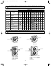
OC247-E--1.qxp 12 04.8.11 4:25 PM Page 25 DISASSEMBLY INSTRUCTIONS NOTE : All panels are clasped, and should be removed by shifting up and down. Outdoor unit (PU18EK) OPERATING PROCEDURE PHOTOS 1. Electrical parts (1) Remove top panel (3 screws in front, 2 screws in rear) (2) Remove cover panel (1 screw). The panel is anchored by clicks to the side panel. Remove by pulling towards you. (3) Remove cover panel (1 screw). The panel is anchored by clicks on the right and left sides.
OC247-E--1.qxp 04.8.11 4:25 PM Page 26 OPERATING PROCEDURE PHOTOS 3. Heat Exchanger, Compressor (1) Remove the rear panel (2 screws in front, 1 screw on the side, 3 screws in the rear). Remove the valve bed, and open the rear panel to the rear to remove. (2) Remove right side panel (4 screws). (3) Remove rear guard (3 screws). (4) Remove separator support plate (4 screws). (5) Remove motor support (2 screws). (6) Remove valve bed (5 screws). The valve bed is clasped on the right and left sides.
OC247-E--1.qxp 04.8.11 4:25 PM Page 27 NOTE : All panels are clasped, and should be removed by shifting up and down. Outdoor unit (PU24EK) OPERATING PROCEDURE PHOTOS 1. Electrical parts (1) Remove top panel (3 screws in front, 2 screws in rear) (2) Remove cover panel (1 screw). The panel is anchored by clicks to the side panel. Remove by pulling towards you. (3) Remove cover panel (1 screw). The panel is clasped on the right and left sides.
OC247-E--1.qxp 04.8.11 4:25 PM Page 28 OPERATING PROCEDURE PHOTOS 3. Heat Exchanger, Compressor (1) Remove the rear / right side panel (2 screws in front, 1 screw on the side, 3 screws in the rear). Remove the electrical box, valve bed, and open to the rear to remove (anchors attached). (2) Remove right side panel (4 screws). (3) Remove rear guard (3 screws). (4) Remove separator support plate (4 screws). (5) Remove motor support (2 screws). (6) Remove valve bed (5 screws).
OC247-E--1.qxp 04.8.11 4:25 PM 13 Page 29 PARTS LIST STRUCTURAL PARTS PU12EK PU18EK PU18EK1 10 9 8 1 7 2 3 4 5 6 Q'ty / set No. Parts No.
OC247-E--1.qxp 04.8.11 4:25 PM Page 30 STRUCTURAL PARTS PU24EK PU30EK PU24EK1 PU30EK1 PU24EK2 PU30EK2 PU24EK3 PU30EK3 12 11 10 9 1 2 3 3 4 5 7 6 8 Q'ty / set Parts Name Specifications PU24EK PU30EK PU24EK1 PU30EK1 PU24EK2 PU30EK2 PU24EK3 PU30EK3 No. Parts No.
OC247-E--2.qxp 04.8.11 4:26 PM Page 31 STRUCTURAL PARTS PU36EK PU42EK2 PU42EK7 PU36EK1 PU42EK21 PU42EK71 PU36EK2 PU42EK72 PU36EK3 12 1 11 10 9 8 2 3 4 4 5 6 7 Q'ty / set No. Parts No. Parts Name Specifications 1 R01 A14 662 SIDE PANEL (LEFT) Wiring Remarks Diagram (Drawing No.
OC247-E--2.qxp 04.8.
OC247-E--2.qxp 04.8.11 4:26 PM Page 33 Q'ty / set No. Parts No.
OC247-E--2.qxp 04.8.
OC247-E--2.qxp 04.8.11 4:26 PM Page 35 Q'ty / set No. Parts No. Parts Name 1 T7W 851 763 FAN MOTOR 2 R01 A00 115 PROPELLER 3 T7W 850 208 HIGH PRESSURE SWITCH 4 5 S6V-60FPN OPEN psiG 363 R01 41L 413 CHARGE PLUG T97 517 300 COMPRESSOR PU Specifications NH33NBD 24EK 24EK1 24EK2 24EK3 2 2 2 2 2 2 1 1 1 2 2 2 1 1 Remarks (Drawing No.
OC247-E--2.qxp 04.8.
OC247-E--2.qxp 04.8.11 4:26 PM Page 37 Q'ty / set No. Parts No.
OC247-E--2.qxp 04.8.
OC247-E--2.qxp 04.8.11 4:26 PM Page 39 Q'ty / set PU No. Parts No.
OC247-E--2.qxp 04.8.
OC247-E--2.qxp 04.8.11 4:26 PM Page 41 Q'ty / set No. Parts No. Parts Name 1 T7W 853 763 FAN MOTOR PA6N100UG 2 R01 A00 115 PROPELLER 3 T7W 850 208 HIGH PRESSURE SWITCH PU Specifications OPEN psiG 469 4 R01 41L 413 CHARGE PLUG 42EK2 42EK21 2 2 2 2 1 1 Wiring Remarks Diagram (Drawing No.
OC247-E--2.qxp 04.8.
OC247-E--2.qxp 04.8.11 4:26 PM Page 43 Q'ty / set No. Parts No. Parts Name PU Specifications Wiring Remarks Diagram (Drawing No.) Symbol 42EK7 42EK71 42EK72 2 2 2 2 1 1 63H2 4 R01 86H 201 DISCHARGE THERMAL SWITCH 1 1 26C 5 R01 41L 413 CHARGE PLUG 2 2 6 T97 513 500 COMPRESSOR ZR42K3PFV 1 1 MC 7 T7W 851 236 CRANKCASE HEATER 240V 43W 1 1 CH 8 R01 670 411 BALL VALVE 3/4 1 1 9 R01 47L 410 BALL VALVE 1/2 1 1 10 T7W E10 425 CAPILLARY TUBE 0.157o0.079o21.
OC247-E--2.qxp 04.8.11 5:24 PM Page 44 TM cCopyright 2001 MITSUBISHI ELECTRIC ENGINEERING CO., LTD. Distributed in Aug. 2004 No.OC247 REVISED EDITION-E PDF 9 Distributed in Aug. 2004 No.OC247 REVISED EDITION-D PDF 9 Distributed in Dec. 2002 No.OC247 REVISED EDITION-C 17 Distributed in Dec. 2002 No.OC247 REVISED EDITION-B 17 Distributed in May. 2001 No.OC247 REVISED EDITION-A 25 Distributed in Mar. 2001 No.OC247 20 New publication, effective Aug. 2004 Specifications subject to change without notice.
3400 Lawrenceville Suwanee Road ● Suwanee, Georgia 30024 Toll Free: 800-433-4822 ● Toll Free Fax: 800-889-9904 www.mrslim.com Specifications are subject to change without notice.