
Service manual


9
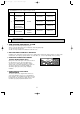
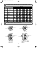
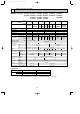
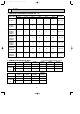
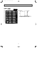
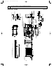
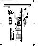
OUTLINES AND DIMENSIONS7
5-7/16
29/32
9/32 11-5/8
1-5/16
13-11/32
3-1/32 20-5/8
1-9/16 20-5/8
11-3/32
11-11/16
17-15/32
25-9/16
34-1/4
11-7/8
2-3/8
2-3/8
4-3/4
2-1/16 1-3/4
4-1/8
15/32
2-9/16
21/32
3-5/32
31/32 max.
R 1/4
R25/32
R25/32
Bottom
piping hole
Front right piping holes - detail Figures
Standard bolt length
2-U-shaped
notched
holes
1-5/16
1-21/32
1-25/32
3-3/4
Handle for moving
Rear fresh
air intake
Outlet guide
installation hole
Terminal bed for indoor and outdoor unit connection
Terminal bed for power line
Refrigerant-pipe flared
connection
5/8
Knock out hole
for front piping
Knock out hole
for front piping
Knock out holes
for power line 1-1/16
15/32 29/32 Oval holes
Drain hole
Drain hole
(standard bolt M10)
(refrigerant, drainage
and wiring)
(refrigerant, drainage
and wiring)
Ground terminal
Handle for moving
Service panel
Handle for
moving
Side air intake
Rear piping hole
Air in
Air in
Air out
7-9/32 7-9/32
14-1/4
1-9/16 1-3/32
11/169/16 13
19-11/16
Refrigerant-pipe flared
connection
3/8
1
Front opening
Service space
(for N.E.C)
1/2
36
36
4
Note:Allow adequate
upper clearance.
1/2
8
1/2
Outdoor Unit - necessary surrounding clearance
Unit : inch
Outdoor Unit PU12EK
40
1/2
Outdoor Unit-Necessary surrounding clearance
(Concentrated installation)
The upper side must be open.
4
8
For 10 units or less
OC247-E--1.qxp 04.8.11 4:25 PM Page 9