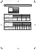
OC305--1.qxp 04.4.28 11:24 AM Page 1 2004 SPLIT-TYPE, HEAT PUMP AIR CONDITIONERS SPLIT-TYPE, AIR CONDITIONERS No.OC305 TECHNICAL & SERVICE MANUAL Series PKA Wall Mounted Indoor unit [Model names] R407C/R410A [Service Ref.] PKA-RP1.6GAL PKA-RP2GAL PKA-RP1.6GAL PKA-RP2GAL • This manual dose not cover outdoor uniits. When servicing tthem, please refer to service manual OC261 REVISED EDITION-B, OC285, OC294 REVISED EDITION-A, OC298 and this manual in a set.
OC305--1.qxp 1 04.4.28 11:24 AM Page 2 COMBINATION OF INDOOR AND OUTDOOR UNITS (R410A Inverter) Indoor unit Outdoor unit [OC294 REVISED EDITION-A] Heat pump type PUHZ-RP 1.6VHA PKA-RP1.6GAL PKA-RP2GAL 2VHA — — (R407C Fixed speed) Indoor unit Outdoor unit [OC285] Heat pump type PUH-P 2VGAA 1.6VGAA Heat pump without PKA-RP1.6GAL electric heater or PKA-RP2GAL Cooling only Outdoor unit [OC298] Cooling only type PU-P 1.
OC305--1.qxp 04.4.28 11:24 AM 2 Page 3 SAFETY PRECAUTION CAUTIONS RELATED TO NEW REFRIGERANT Cautions for units utilizing refrigerant R407C Do not use the existing refrigerant piping. Use liquid refrigerant to seal the system. The old refrigerant and lubricant in the existing piping contains a large amount of chlorine which may cause the lubricant deterioration of the new unit.
OC305--1.qxp 04.4.28 11:24 AM Page 4 [3] Service tools Use the below service tools as exclusive tools for R407C refrigerant. No. 1 Tool name Gauge manifold Specifications ·Only for R407C. ·Use the existing fitting SPECIFICATIONS. (UNF7/16) ·Use high-tension side pressure of 3.43MPa·G or over. 2 Charge hose 3 Electronic scale 4 Gas leak detector ·Use the detector for R134a or R407C. 5 Adapter for reverse flow check. ·Attach on vacuum pump. 6 Refrigerant charge base. 7 Refrigerant cylinder.
OC305--1.qxp 04.4.28 11:24 AM Page 5 CAUTIONS RELATED TO NEW REFRIGERANT Cautions for units utilizing refrigerant R410A Use new refrigerant pipes. Do not use refrigerant other than R410A. In case of using the existing pipes for R22, be careful with the followings. · Change flare nut to the one provided with this product. Use a newly flared pipe. · Avoid using thin pipes. If other refrigerant (R22 etc.) is used, chlorine in refrigerant can cause deterioration of refrigerant oil etc.
OC305--1.qxp 04.4.28 11:24 AM Page 6 Unit Gravimeter [3] Service tools Use the below service tools as exclusive tools for R410A refrigerant. No. 1 Specifications Gauge manifold ·Only for R410A ·Use the existing fitting specifications. (UNF1/2) ·Use high-tension side pressure of 5.3MPa·G or over. 2 Charge hose 3 Electronic scale 4 Gas leak detector ·Use the detector for R134a, R407C or R410A. 5 Adaptor for reverse flow check ·Attach on vacuum pump.
OC305--1.qxp 04.4.28 11:24 AM Page 7 ●Wireless remote controller ● When cover is open. CHECK TEST RUN display CHECK&TEST RUN display indicates that the unit is being checked or test-run. MODEL SELECT display Blinks when model is selected. display Lights up while transmission to the indoor unit is mode using switches. display SET TEMP. display indicates desired temperature set. CLOCK display display Displays the current time.
OC305--1.qxp 04.4.28 11:24 AM Page 8 SPECIFICATIONS 4 4-1. Heat pump type (1) Service Ref. Item Function Btu/h W kW Capacity INDOOR UNIT Total input Service Ref. Power supply(phase, cycle, voltage) Input Running current Starting current External finish Heat exchanger Fan Fan(drive) x No. Fan motor output Airflow(Lo-Mi2-Mi1-Hi) External static pressure Operation control & Thermostat Noise level(Lo-Mi2-Mi1-Hi) Unit drain pipe O.D. Dimensions W D H Weight OUTDOOR Service Ref. UNIT PKA-RP1.
OC305--1.qxp 04.4.28 11:24 AM Page 9 4-2. Heat pump type (2) Service Ref. Item Function INDOOR UNIT OUTDOOR UNIT 0.07 0.33 0.40 kW A A 0.07 0.33 0.40 Munsell 0.70Y 8.59/0.97 Plate fin coil Line flow (direct) x 1 0.030 9-10-11-12(320-355-390-425) 0(direct blow) Wireless remote controller & built-in 36-38-41-43 26(1) 990(39) 235(9-1/4) 340(13-3/8) 16(35) PUH-P1.6VGAA PUH-P1.6VGAA.UK / PUH-P1.6YGAA.UK PUH-P1.6VGAA1.UK / PUH-P1.6YGAA1.UK kW K/min(CFM) Pa(mmAq) dB mm(in.) mm(in.) mm(in.) mm(in.
OC305--1.qxp 04.4.28 11:24 AM Page 10 4-3. Cooling only type Service Ref. Item Function Capacity INDOOR UNIT Total input Service Ref. Power supply(phase, cycle, voltage) Input Running current Starting current External finish Heat exchanger Fan Fan(drive) x No. Fan motor output Airflow(Lo-Mi2-Mi1-Hi) External static pressure Operation control & Thermostat Noise level(Lo-Mi2-Mi1-Hi) Unit drain pipe O.D. Dimensions W D H Weight OUTDOOR UNIT PKA-RP1.6GAL Cooling 15,200 4,450 1.70 PKA-RP1.
OC305--1.qxp 04.4.28 11:24 AM Page 11 DATA 5 5-1. PERFORMANCE DATA COOLING CAPACITY(1) PKA-RP1.6GAL / PUHZ-RP1.6VHA (230V) Indoor Indoor Intake air Intake air D.B.(°C) W.B.(°C) CA 20 SHC(W) SHF P.C. Outdoor intake air D.B.(°C) 25 CA SHC(W) SHF P.C. CA 30 SHC(W) SHF P.C. 20 16 3,564 2,637 0.74 0.82 3,456 2,257 0.74 0.87 3,348 2,478 0.74 0.92 20 18 3,816 2,366 0.62 0.84 3,708 2,299 0.62 0.89 3,582 2,221 0.62 0.95 20 20 4,104 2,052 0.50 0.87 4,014 2,007 0.50 0.
OC305--1.qxp 04.4.28 11:24 AM Page 12 COOLING CAPACITY(2) PKA-RP1.6GAL / PUHZ-RP1.6VHA (230V) Indoor Indoor Intake air Intake air D.B.(°C) W.B.(°C) CA 35 SHC(W) SHF P.C. Outdoor intake air D.B.(°C) 40 CA SHC(W) SHF P.C. CA 45 SHC(W) SHF P.C. 20 16 3,204 2,371 0.74 0.99 3,060 2,264 0.74 1.06 2,916 2,158 0.74 1.15 20 18 3,456 2,143 0.62 1.01 3,348 2,076 0.62 1.09 3,132 1,942 0.62 1.17 20 20 3,744 1,872 0.50 1.04 3,600 1,800 0.50 1.11 3,384 1,692 0.50 1.
OC305--1.qxp 04.4.28 11:24 AM Page 13 COOLING CAPACITY(3) PKA-RP2GAL / PUHZ-RP2VHA (230V) Indoor Indoor Intake air Intake air D.B.(°C) W.B.(°C) CA 20 SHC(W) SHF P.C. Outdoor intake air D.B.(°C) 25 CA SHC(W) SHF P.C. CA 30 SHC(W) SHF P.C. 20 16 4,554 2,915 0.64 1.30 4,416 2,826 0.64 1.38 4,278 2,738 0.64 1.46 20 18 4,876 2,536 0.52 1.33 4,738 2,464 0.52 1.40 4,577 2,380 0.52 1.50 20 20 5,244 2,098 0.40 1.37 5,129 2,052 0.40 1.43 4,991 1,996 0.40 1.
OC305--1.qxp 04.4.28 11:24 AM Page 14 COOLING CAPACITY(4) PKA-RP2GAL / PUHZ-RP2VHA (230V) Indoor Indoor Intake air Intake air D.B.(°C) W.B.(°C) CA 35 SHC(W) SHF P.C. Outdoor intake air D.B.(°C) 40 CA SHC(W) SHF P.C. CA 45 SHC(W) SHF P.C. 20 16 4,094 2,620 0.64 1.56 3,910 2,502 0.64 1.68 3,726 2,385 0.64 1.82 20 18 4,416 2,296 0.52 1.61 4,278 2,225 0.52 1.73 4,022 2,081 0.52 1.86 20 20 4,784 1,914 0.40 1.65 4,600 1,840 0.40 1.76 4,324 1,730 0.40 1.
OC305--1.qxp 04.4.28 11:24 AM Page 15 COOLING CAPACITY(5) PKA-RP1.6GAL / PUH-P1.6VGAA PUH-P1.6VGAA.UK PUH-P1.6VGAA1.UK PU-P1.6VGAA PU-P1.6VGAA.UK PU-P1.6VGAA1.UK Indoor Indoor Intake air Intake air D.B.(°C) W.B.(°C) CA PUH-P1.6YGAA.UK PUH-P1.6YGAA1.UK PU-P1.6YGAA.UK PU-P1.6YGAA1.UK 20 SHC(W) SHF P.C. (230V) Outdoor intake air D.B.(°C) 25 CA SHC(W) SHF P.C. CA 30 SHC(W) SHF 20 16 4,406 2,952 0.67 1.36 4,272 2,862 0.67 1.44 4,139 2,773 0.67 P.C. 1.52 20 18 4,417 2,594 0.55 1.
OC305--1.qxp 04.4.28 11:24 AM Page 16 COOLING CAPACITY(6) PKA-RP1.6GAL / PUH-P1.6VGAA PUH-P1.6VGAA.UK PUH-P1.6VGAA1.UK PU-P1.6VGAA PU-P1.6VGAA.UK PU-P1.6VGAA1.UK Indoor Indoor Intake air Intake air D.B.(°C) W.B.(°C) CA PUH-P1.6YGAA.UK PUH-P1.6YGAA1.UK PU-P1.6YGAA.UK PU-P1.6YGAA1.UK 35 SHC(W) SHF P.C. (230V) Outdoor intake air D.B.(°C) 40 CA SHC(W) SHF P.C. 45 CA SHC(W) SHF P.C. 20 16 3,961 2,654 0.67 1.63 3,783 2,534 0.67 1.75 3,605 2,415 0.67 1.90 20 18 4,272 2,350 0.55 1.
OC305--1.qxp 04.4.28 11:24 AM Page 17 COOLING CAPACITY(7) PKA-RP2GAL / PUH-P2VGAA PUH-P2VGAA.UK PUH-P2VGAA1.UK PU-P2VGAA PU-P2VGAA.UK PU-P2VGAA1.UK Indoor Indoor Intake air Intake air D.B.(°C) W.B.(°C) CA PUH-P2YGAA.UK PUH-P2YGAA1.UK PU-P2YGAA.UK PU-P2YGAA1.UK 20 SHC(W) SHF P.C. (230V) Outdoor intake air D.B.(°C) 25 CA SHC(W) SHF P.C. CA 30 SHC(W) SHF P.C. 20 16 5,297 3,178 0.60 1.86 5,136 3,082 0.60 1.97 4,976 2,985 0.60 2.09 20 18 5,671 2,722 0.48 1.90 5,511 2,645 0.
OC305--1.qxp 04.4.28 11:24 AM Page 18 COOLING CAPACITY(8) PKA-RP2GAL / PUH-P2VGAA PUH-P2VGAA.UK PUH-P2VGAA1.UK PU-P2VGAA PU-P2VGAA.UK PU-P2VGAA1.UK Indoor Indoor Intake air Intake air D.B.(°C) W.B.(°C) CA PUH-P2YGAA.UK PUH-P2YGAA1.UK PU-P2YGAA.UK PU-P2YGAA1.UK 35 SHC(W) SHF P.C. (230V) Outdoor intake air D.B.(°C) 40 CA SHC(W) SHF P.C. 45 CA SHC(W) SHF P.C. 20 16 4,762 2,857 0.60 2.24 4,548 2,729 0.60 2.40 4,334 2,600 0.60 2.60 20 18 5,136 2,465 0.48 2.30 4,976 2,388 0.
OC305--1.qxp 04.4.28 11:24 AM Page 19 HEATING CAPACITY (1) PKA-RP•GAL / PUHZ-RP•VHA (230V) Indoor Service Ref. intake are D.B. (˚C) 15 PKA-RP1.6GAL 20 25 15 PKA-RP2GAL 20 25 NOTE: CA: Capacity (W) -10 CA 2,604 2,501 2,419 2,858 2,745 2,655 -5 P.C. 0.75 0.81 0.86 0.83 0.90 0.95 CA 2,829 2,706 2,624 3,105 2,970 2,880 P.C. 0.83 0.89 0.97 0.91 0.98 1.06 Outdoor intake air W.B. (:) 0 5 CA P.C. CA P.C. 3,157 0.95 4,141 1.14 2,993 1.03 3,998 1.23 2,870 1.12 3,772 1.31 3,465 1.05 4,545 1.26 3,285 1.
OC305--1.qxp 04.4.28 11:24 AM Page 20 5-2. PERFORMANCE CURVE PKA-RP•GAL / PUHZ-RP•VHA Cooling performance curve(50Hz) Heating performance curve(50Hz) Correcting the capacity line influenced by frosting Not correcting the capacity line influenced by frosting 1.4 INDOOR W.B.(°C) 1.2 22 1.0 20 18 0.8 16 CAPACITY (RATIO) CAPACITY (RATIO) 1.4 1.2 In some cases, heating operation cannot be conducted with the maximum frequency in the area below the slanting line. 15 20 25 INDOOR D.B.
OC305--1.qxp 04.4.28 11:24 AM Page 21 5-3. Correction factors PKA-RP•GAL / PUHZ-RP•VHA Cooling capacity correction factors 5m 10m 20m Refrigerant piping length (one way) 30m 40m 55m 50m PKA-RP1.6GAL 1.00 0.992 0.976 0.962 0.949 0.936 PKA-RP2GAL 1.00 0.985 0.957 0.931 0.908 0.886 Service Ref. 60m 70m 80m 0.930 — — — 0.876 — — — Heating capacity correction factors 5m 10m 20m Refrigerant piping length (one way) 30m 40m 50m 55m 60m 70m 80m PKA-RP1.6GAL 1.00 0.997 0.
OC305--1.qxp 04.4.28 11:24 AM Page 22 5-4. STANDARD OPERATION DATA Heat pump type (1) Service Ref. PKA-RP1.6GAL Total Mode Cooling Heating Cooling Heating Capacity W 3,600 4,100 4,600 4,500 Input kW 1.03 1.27 1.63 1.40 Indoor unit Service Ref. PKA-RP1.6GAL PKA-RP2GAL 1 , 50 1 , 50 230 230 Electrical circuit Phase , Hz Volts Amperes Outdoor unit Service Ref. PUHZ-RP1.6VHA PUHZ-RP2VHA 1 , 50 1 , 50 230 230 Phase , Hz Refrigerant circuit Amperes 0.33 0.33 0.33 0.
OC305--1.qxp 04.4.28 11:24 AM Page 23 Heat pump type (2) Service Ref. PKA-RP1.6GAL Total Mode Cooling Heating Cooling Heating Cooling Heating Cooling Heating Capacity W 4,450 4,950 4,450 4,950 5,350 6,200 5,350 6,200 Input kW 1.70 Indoor unit Service Ref. 1.79 Electrical circuit 0.33 2.33 2.34 2.33 2.34 1 , 50 1 , 50 230 230 0.33 0.33 0.33 0.33 0.33 0.33 0.33 PUH-P1.6VGAA PUH-P2VGAA Outdoor unit Service Ref. PUH-P1.6VGAA.UK PUH-P1.6YGAA.UK PUH-P2VGAA.UK PUH-P2YGAA.UK PUH-P1.
OC305--1.qxp 04.4.28 11:24 AM Page 24 Cooling only type Service Ref. PKA-RP1.6GAL Total Mode Cooling Cooling Cooling Cooling Capacity W 4,450 4,450 5,350 5,350 Input kW 1.70 1.70 2.33 2.33 Indoor unit Service Ref. PKA-RP1.6GAL PKA-RP2GAL 1 , 50 1 , 50 230 230 Phase , Hz Refrigerant circuit Electrical circuit Volts Outdoor Indoor side side PKA-RP2GAL Amperes 0.33 0.33 0.33 0.33 PU-P1.6VGAA PU-P2VGAA Outdoor unit Service Ref. PU-P1.6VGAA.UK PU-P1.6YGAA.UK PU-P2VGAA.
OC305--1.qxp 04.4.28 11:24 AM Page 25 5-6. NOISE CRITERION CURVES NOTCH SPL(dB) Hi 43 Mi1 41 38 Mi2 Lo 36 PKA-RP1.6GAL PKA-RP2GAL LINE OCTAVE BAND SOUND PRESSURE LEVEL, dB re 0.
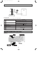
360 495 Sleeve w1 [90 MITSUBISHI ELECTRIC 150 or more m r.SLI m Through hole [90~[100 245 70 21 R52.5 Liquid pipe Gas pipe 990 705 Air outlet 80 715 Air intake 400 12-Louvers(manual) 340 Air intake ëOñ Å@ÇeÇqÇnÇmÇs ëOñ Å@ÇeÇqÇnÇmÇs 449 581 ÅrÇoÇoÅqÅ@ 1.6, 2 Model 225 40 86 54 70 35 MITSUBISHI ELECTRIC mr.SLIm 190 160 235 ON STAND COOL HEAT OFF BY 233 153 Knock out hole for right piping Refrigerant pipe.Drain pipe.
OC305--1.qxp 04.4.28 11:24 AM Page 27 WIRING DIAGRAM 7 PKA-RP1.6GAL PKA-RP2GAL INDOOR UNIT MF DC14V ZNR POWER 1 3 5 CN03 (RED) 1 3 5 FC TB4 YLW S1 ORN S2 BRN S3 1 2 3 CONT.BOARD CN02(WHT) BLK WHT YLW ORN BRN RED WHT BLK C FAN (WHT) F1 3 2 1 3 2 1 I.B P.B CN2S(WHT) 2 1 ] OUTDOOR CN01(BLU) VANE CN6V (WHT) 1 2 POWER CN2D(WHT) X4 CN41 CN2L X4 CN25 CN32 TO OUTDOOR UNIT 6 MV WIRELESS CN90 (WHT) 9 9 W.
OC305--1.qxp 8 04.4.28 11:24 AM Page 28 REFRIGERANT SYSTEM DIAGRAM PKA-RP1.
OC305--1.qxp 04.4.28 11:24 AM 9 Page 29 TROUBLESHOOTING 9-1. TROUBLESHOOTING Present and past error codes are logged and displayed on the wired remote controller or controller board of outdoor unit. Actions to be taken for service and the inferior phenomenon reoccurrence at field are summarized in the table below. Check the contents below before investigating details.
OC305--1.qxp 04.4.28 11:24 AM Page 30 9-2. Malfunction-diagnosis method by remote controller When a malfunction occurs to air conditioner, both indoor unit and outdoor unit will stop and operation lamp blinks to inform unusual stop. [Procedure] 1. Press the CHECK button twice. • "CHECK" lights, and refrigerant address "00" flashes. • Check that the remote controller's display has stopped before continuing. 2.
OC305--2.qxp 04.4.28 11:25 AM Page 31 Note: Refer to the manual of outdoor unit for the details of display such as F, U, and other E. 9-3. SELF-DIAGNOSIS ACTION TABLE Error Code Meaning of error code and detection method Abnormality of room temperature thermistor (TH1) 1 The unit is in three-minute resume prevention mode if short/open of thermistor is detected. Abnormal if the unit does not reset normally after three minutes. (The unit returns to normal operation, if it has normally reset.
OC305--2.qxp 04.4.28 11:25 AM Page 32 Error Code Meaning of error code and detection method Freezing/overheating protection is working 1 Freezing protection (Cooling mode) The unit is in six-minute resume prevention mode if pipe temperature stays under -15: for three minutes, three minutes after the compressor started. Abnormal if it stays under -15: for three minutes again within 16 minutes after six-minute resume prevention mode.
OC305--2.qxp 04.4.28 11:25 AM Page 33 Error Code Meaning of error code and detection method Abnormality of pipe temperature thermistor / Condenser-Evaporator (TH5) 1 The unit is in three-minute resume protection mode if short/open of thermistor is detected. Abnormal if the unit does not get back to normal within three minutes. (The unit returns to normal operation, if it has normally reset.
OC305--2.qxp 04.4.28 11:25 AM Page 34 9-4. TROUBLESHOOTING BY INFERIOR PHENOMENA Note: Refer to the manual of outdoor unit for the detail of remote controller. Phenomena (1)LED2 on indoor controller board is off. Cause Countermeasure • When LED1 on indoor controller board is also off. 1 Power supply of 220~240V is not supplied to outdoor 1 Check the voltage of outdoor power supply terminal block (L, N) unit. • When AC 220~240V is not detected. Check the power wiring to outdoor unit and the breaker.
OC305--2.qxp 04.4.28 11:25 AM Page 35 9-5. EMERGENCY OPERATION 9-5-1. When wireless remote controller troubles or its battery is exhausted 1. Emergency operation is available in such a case using emergency operation switch equipped next to the receiver of indoor unit. 2. To start operation • Cooling Operation·······Press (Cooling) switch. • Heating Operation·······Press (Heating) switch. wWhen the unit starts operating, the power lamp is lit.
OC305--2.qxp 04.4.28 11:25 AM Page 36 9-6. How to check the parts PKA-RP1.6GAL PKA-RP2GAL Parts name Check points Room temperature thermistor (TH1) Pipe temperature thermistor/liquid(TH2) Condenser/evaporator temperature thermistor (TH5) Fan motor (MF) Disconnect the connector then measure the resistance using a tester. (Surrounding temperature 10:~30:) Red 2 White 3 Black 1 2 4 Orange 2 Pink Open or short Red–Black 120.5" White–Black 111.
OC305--2.qxp 04.4.28 11:25 AM Page 37 9-7. TEST POINT DIAGRAM 9-7-1. Indoor controller board PKA-RP1.6GAL PKA-RP2GAL CN2D Connect to the indoor power board (CN2S) 12~16V DC + – LED1 Power supply (I.
OC305--2.qxp 04.4.28 11:25 AM Page 38 9-7-2. Indoor power board PKA-RP1.6GAL PKA-RP2GAL – + } CN2S Connect to the indoor controller board (CN2D) (12~16V DC) CN02 Connect to the indoor controller board (CN03) + Between 1 and 2 0~24V DC – (Indoor/Outdoor transmission) Between 2 and 3 220~240V AC } + – } Fuse 4A/250V CN01 Connect to the Terminal Block (TB4) (Indoor/outdoor connecting line) Between 1 and 2 220~240V AC Between 2 and 3 0~24V DC (Indoor/outdoor transmission) 9-8.
OC305--2.qxp 04.4.28 11:25 AM 10 Page 39 DISASSEMBLY PROCEDURE PKA-RP1.6GAL PKA-RP2GAL OPERATION PROCEDURE PHOTOS & ILLUSTRATION 1. REMOVE THE LOWER SIDE OF THE INDOOR UNIT FROM THE INSTALLATION PLATE. (1) Remove the left / right corner box of the indoor unit. (2) Hold and pull down the lower and both ends of the indoor unit, and remove the ▼ section from the square hole. (Refer to the figure 2.1) Or remove the front panel and push the ▼ section down by using hexagonal wrench ,etc.
OC305--2.qxp 04.4.28 11:25 AM Page 40 OPERATION PROCEDURE PHOTOS & ILLUSTRATION 4. REMOVING THE POWER BOARD (1) Remove the front panel.(see the photo 1) (2) Remove the electrical parts box(2screws).(see the photo 2) (3) Disconnect the whole connector in the control board. (4) After lifting the controller case with pressing it’s convex section, remove the controller case and the control board simultaneously.(see the photo 3) (5) Disconnect the connector in the power board. (6) Remove the power board.
OC305--2.qxp 04.4.28 11:25 AM Page 41 OPERATION PROCEDURE PHOTOS & ILLUSTRATION 9. REMOVING THE FAN MOTOR. (1) Remove the terminal block cover. (2) Remove the front panel.(see the photo 1) (3) Remove the electrical parts box.(see the photo 8) (4) Remove the nozzle assemble.(see the photo 7) (5) Remove the fan motor leg fixing 3screws. (6) Unscrew the set screws using by alankey and remove it by sliding the fan motor to right. (7) Remove the 4screws and remove the motor cover from the fan motor leg.
OC305--2.qxp 11 04.4.28 11:25 AM Page 42 PARTS LIST STRUCTURAL PARTS PKA-RP1.6GAL PKA-RP2GAL 1 2 4 3 12 5 6 11 13 14 8 7 10 9 Q'ty/set No. Parts No. 15 Parts Name Specifications Wiring RecomRemarks Diagram mended PKA-RP1.6GAL (Drawing No.
OC305--2.qxp 04.4.28 11:25 AM Page 43 ELECTRICAL PARTS PKA-RP1.6GAL 4 PKA-RP2GAL 1 3 2 33 32 5 6 30 7 9 26 31 25 1 24 23 29 27 17 8 28 10 11 12 16 15 10 19 20 14 13 No. 1 2 3 4 5 6 7 8 9 10 11 12 13 14 15 16 17 18 19 20 21 22 23 24 25 26 27 28 29 30 31 32 33 Parts No.
OC305--2.qxp 12 04.4.28 11:25 AM Page 44 OPTIONAL PARTS 12-1. Wired Remote Controller (with terminal bed). Part No. PAR-20MAAT-E 12-2. Program Timer Part No. PAC-SC32PTA 12-3. Remote Sensor Part No. PAC-SE41TS-E 12-4. Remote Operation Adapter Part No. PAC-SF40RM-E 12-5. Remote ON/OFF Adapter Part No. PAC-SE55RA-E HEAD OFFICE : MITSUBISHI DENKI BLDG., 2-2-3, MARUNOUCHI, CHIYODA-KU, TOKYO100-8310, JAPAN cCopyright 2004 MITSUBISHI ELECTRIC ENGINEERING CO.,LTD Distributed in May 2004 No.