M-SERIES & P-SERIES Pocket Reference Guide CounterPRO Your #1 Support Team mitsubishipro.com © 2012 Mitsubishi Electric & Electronics USA, Inc. I Form No.
Pre-visit Checklist 3 Verify appointment 3 Call 30 minutes before you arrive 3 Verify equipment in stock at distributor 3 Credit application/financing options 3 Local rebate information 3 Bring this booklet along so you have product information and the contact phone numbers below handy Inside Sales: 866-323-4822 Service: 877-391-5550 M-Series Applications: 800-433-4822 (press 3) Parts: 678-376-2940 www.mitsubishipro.
Advanced Technology. Superior Comfort. Split-zoning is the most popular type of air-conditioning technology in the world. Mitsubishi Electric takes split-zoning to a new level—our cooling and heating systems deliver year-round personal comfort even in the harshest of climates.
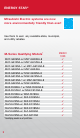
ENERGY STAR® Mitsubishi Electric systems are now more environmentally friendly than ever! Use them to earn any available state, municipal, and utility rebates.
Energy Star MXZ-2B20NA-1 with 2 non-ducted indoor units 2 MSZ-GE09NA-8 MXZ-3B24NA-1 with 3 non-ducted indoor units 2 MSZ-GE06NA-8 and 1 MSZ-GE09NA-8 or 1 MSZ-GE12NA-8 P-Series Qualifying Models* PUZ-HA30NHA4 PUZ-HA30NHA4 PUZ-HA30NHA4 PUZ-HA30NHA4 PUZ-HA36NHA4 PUZ-HA36NHA4 PUZ-HA36NHA4 PUZ-HA36NHA4 PUZ-HA36NHA4 w/ w/ w/ w/ w/ w/ w/ w/ w/ PCA-A30KA4 PEAD-A30AA4 PKA-A30KA4 PLA-A30BA4 PCA-A36KA4 PEAD-A36AA4 PKA-A36KA4 (2) PEA-A18AA4 PLA-A36BA4 3 3 3 3 Energy Star 3 3 3 3 3 3 3 3 3 *Qualifying model as of
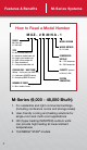
Features & Benefits M-Series Systems How to Read a Model Number M X Z - 2 B 20 N A - 1 FAMILY M = Mini-split S = Mini-split TYPE S = Wall-mounted indoor unit E = Horizontal-ducted indoor unit U = Single system outdoor unit X = Multi-system outdoor unit F = Floor-mounted unit L = Ceiling recessed indoor unit COOLING ONLY / HEAT PUMP Nothing = Cooling only (non-INVERTER) Y = Cooling only (INVERTER-driven) Z = Heat pump (INVERTER-driven) NUMBER OF ZONES MODEL VERSION WIRING METHOD A = A Control COMPRESS
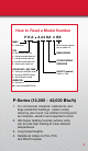
How to Read a Model Number pka a 24 Ka 4 bs FAMILY P = Professional TYPE K = Wall-mounted indoor unit C = Ceiling-suspended indoor unit L = Ceiling-recessed indoor unit E = Horizontal-ducted indoor unit U = Single system outdoor unit COOLING ONLY / HEAT PUMP Y = Cooling only (INVERTER-driven) Z = Heat pump (INVERTER-driven) A = Both heating and cooling BS = Seacoast protection pkg.
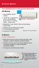
M-Series Models Our standard line is now greener than ever! GE Models Eight ENERGY STAR® models ▶▶ “Smart Set" programming (9,000 - 22,500 Btu/h) button with SETBACK down to 50º F in heating (9,000 - 18,000 only) ▶▶ Washable 10-year catechin filter and anti-allergy enzyme filter ▶▶ Cooling-only and heat pump models ▶▶ Five fan speeds plus AUTO See page 12-15 for more information.
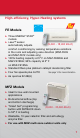
High-efficiency, Hyper-Heating systems FE Models Three ENERGY STAR® models ▶▶ i-see™ sensor (9,000 - 18,000 Btu/h) automatically adjusts comfort conditioning by sensing temperature variations in the room and adjusting vane direction (MSZ-FE09 and MSZ-FE12 models only) ▶▶ 100% heating capacity at 5º F on MSZ-FE09NA and MSZ-FE18NA; 92% capacity at 5º F on MSZ-FE12NA ▶▶ Standard filters plus platinum catalyst deodorizing filter ▶▶ Four fan speeds plus AUTO See page 14 for more information.
M-Series Models SEZ Models (8,100 – 17,200 Btu/h) Small compact design (7-7/8" height) Adjustable static pressure ▶▶ Built-in condensate lift mechanism (22-1/2" lift) ▶▶ Rear return or bottom return (with optional accessory) ▶▶ Low operating sound pressure levels; as low as 23 dB(A) ▶▶ All four models ENERGY STAR® rated ▶▶ ▶▶ See page 16-17 for more information.
M-Series Models Multi-Zone Heat Lineup MXZ Multi-Zone Heat Pumps In door U n i ts : 2:1, 3:1, 4:1, and 8:1 Zoned Solutions (20,000-48,000 Btu/h) hree combinations qualify T for ENERGY STAR® ▶▶ Precise, individual room comfort control ▶▶ Multiple indoor air handler options (ductless and ducted) ▶▶ Minimum of two indoor units must be installed ▶▶ MSZ-FE09 -18NA MSZ-GE06-24NA SLZ-KA09-15NA PLA-A12-24BA4 MF Z- K A 09-18NA (for use with MXZ-B only) select systems Outd o o r Uni ts: M XZ-2 B2 0NA -1 (2:
M-Series Models Di am ond C o m f o r t M X Z MXZ-8B48NA Outdoor Unit SEZ Horizontal-DUCTED INDOOR UNITS SEZ-KD09-18NA4 Models 10 MFZ FLOOR-MOUNTED Indoor units MFZ-KA09-18NA Models (for use with MXZ-B units only)
M ulti-zone S ys t e m s MSZ WALL-MOUNTED INDOOR UNITS MSZ-FE09-18NA MSZ-GE06-24NA PEAD Horizontal-DUCTED INDOOR UNITS PEAD-A24AA4 Models SLZ CEILING-RECESSED Indoor units SLZ-KA09-15NA PLA-A12-24BA4 Models 11
M-Series Cooling Only MS/MSY Model Specifications (air conditioners) *Non-INVERTER Models Indoor Model # Outdoor Model # *MS-A09WA *MS-A12WA MSY-GE09NA-8 MSY-GE12NA-8 *MU-A09WA *MU-A12WA MUY-GE09NA MUY-GE12NA Rated Cooling Capacity (Btu/h) 9,500 12,000 Cooling Capacity Range (Btu/h) 9,500 12,000 13 13 SEER Lineset Size (Liquid x Gas) 1/4" x 3/8" 1/4" x 1/2" 9,000 12,000 3,800-12,200 3,800-13,600 21 20.5 1/4" x 3/8" 1/4" x 3/8" Lineset Length/ Height Max.
MUY-GE15NA-1 MSY-GE15NA-8 MSY-GE15NA-8 MSY-GE18NA-8 MSY-GE24NA MSY-D30NA-8 MSY-D36NA-8 MUY-GE15NA-1 MUY-GE18NA-1 MUY-GE24NA MUY-D30NA-1 MUY-D36NA-1 14,000 17,200 22,500 30,700 34,600 3,100-18,200 3,700-18,700 8,200-31,400 9,800-30,700 9,800-34,600 21 19.2 19 16 15.1 1/4" x 1/2" 1/4" x 1/2" 3/8" x 5/8" 3/8" x 5/8" 3/8" x 5/8" 65'/40' 100'/50' 100'/50' 100'/50' 100'/50' 15 AMP 15 AMP 20 AMP 25 AMP 25 AMP M-Series units are pre-charged for up to a 25' line set.
M-Series Heat Pumps MSZ/MUZ Model Specifications (heat pumps) Indoor Model # MSZ-FE09NA-8 MSZ-FE12NA-8 MSZ-FE18NA MSZ-GE09NA-8 Outdoor Model # MUZ-FE09NA-1 MUZ-FE12NA1 MUZ-FE18NA MUZ-GE09NA Rated Cooling Capacity (Btu/h) 9,000 12,000 18,000 9,000 Cooling Capacity Range (Btu/h) 2,8009,000 2,80012,000 8,20025,200 3,80012,200 3,00018,000 3,00021,000 7,50029,700 4,50014,100 12,500 13,600 19,300 8,700 10,900 12,500 21,600 7,061 26/10 23/10.5 20.2/10.
MUZ-FE09NA-1 MSZ-FE09NA-8 MSZGE12NA-8 MUZ-GE12NA MSZGE15NA-8 MUZGE15NA-1 MSZMSZ-GE24NA GE18NA-8 MUZMUZ-GE24NA GE18NA-1 MSZD30NA-8 MUZD30NA-1 MSZD36NA-8 MUZD36NA-1 12,000 14,000 17,200 22,500 30,700 33,200 3,80013,600 3,10018,200 3,70018,700 8,20031,400 9,80030,700 9,80033,200 5,50018,100 4,80020,900 3,50025,200 7,50036,900 8,70034,000 8,70036,000 11,200 15,900 17,200 24,600 20,800 22,800 9,194 13,022 13,562 21,160 16,305 19,090 20.5/10 21/10 19.2/10 19/10 14.5/8.
SEZ/SLZ Models Specifications (heat pumps) SEZ-KD15NA4 SUZ-KA15NA Indoor Model # SEZ-KD09NA4 SEZ-KD12NA4 SEZ-KD15NA4 Outdoor Model # SUZ-KA09NA SUZ-KA12NA SUZ-KA15NA 8,100 11,500 14,100 Cooling Capacity Range (Btu/h) 3,800-10,900 3,800-13,300 3,800-17,000 Heating Capacity Range at 47ºF (Btu/h) 4,800-14,100 4,800-16,400 4,800-21,100 Max Heating Capacity at 17ºF (Btu/h) 6,700 9,000 11,900 SEER/HSPF 15/10 16/10 15.
All Controllers Ordered separately SLZ-KA15NA MHK1 TM SEZ-KD18NA4 SLZ-KA09NA SLZ-KA12NA SLZ-KA15NA SUZ-KA18NA SUZ-KA09NA SUZ-KA12NA SUZ-KA15NA 17,200 8,400 11,100 15,000 3,800-19,000 3,100-10,900 3,400-13,300 3,800-17,700 4,800-24,900 3,100-14,100 3,100-17,100 3,100-22,200 13,100 6,200 8,300 12,000 17.5/10 15/9.6 15.4/9.6 16/9.
MXZ Series MXZ Model Specifications (multi-zone heat pumps) Outdoor Model # MXZ-2B20NA-1 MXZ-3B24NA-1 MXZ-3B30NA-1 Rated Cooling Capacity (Btu/h) 18,000 22,000 28,400 Cooling Capacity Range (Btu/h) 7,800-20,000 12,600-25,500 12,600-28,400 Heating Capacity Range at 47°F (Btu/h) 8,500-25,500 11,400-30,600 11,400-36,000 Max. Heating Capacity at 17°F (Btu/h) 14,500 18,800 18,800 Max. Heating Capacity at 5°F (Btu/h) 11,113 13,336 15,704 Individual/Combined Max.
MXZ-4B36NA-1 MXZ-8B48NA 35,400 48,000 12,600-36,400 12,000-54,000 11,400-43,000 12,000-60,000 24,600 36,600 18,671 32,400 82'/230' 230'/377' 49'*/33’ 66'**/98' 25 AMP 50 AMP 18.0/9.3 15.0/8.7 16.5/9.2 14.8/8.8 15.0/9.0 14.7/8.9 MXZ-8B48NA BRANCH BOX FOR INDOOR UNIT CONNECTIONS Each MXZ-8B48NA requires at least one branch box with a maximum of two. Two sizes are available: 3-branch (PAC-AKA31BC) and 5-branch (PAC-AKA51BC, shown above).
MXZ-Series Port Adapters Port AdaptEr Guide Available Indoor Units Line set size MSZ Wall-mounted MSZ-GE06NA-8 3/8" gas x 1/4" liquid MSZ-GE09NA-8 3/8" gas x 1/4" liquid MSZ-FE09NA-8 3/8" gas x 1/4" liquid MSZ-GE12NA-8 3/8" gas x 1/4" liquid MSZ-FE12NA-8 3/8" gas x 1/4" liquid MSZ-GE15NA-8 1/2" gas x 1/4" liquid MSZ-FE18NA 5/8" gas x 3/8" liquid MSZ-GE18NA-8 1/2" gas x 1/4" liquid MSZ-GE24NA 5/8" gas x 3/8" liquid MFZ Floor-standing MFZ-KA09NA 3/8" gas x 1/4" liquid MFZ-KA12NA 3/8" ga
MXZ-2B20NA-1 MXZ-3B30NA-1 Port A = 3/8" gas x 1/4" liquid Port A = 1/2" gas x 1/4" liquid Port B = 3/8" gas x 1/4" liquid Port B = 3/8" gas x 1/4" liquid Port C = 3/8" gas x 1/4" liquid MXZ-3B24NA-1 Port A = 1/2" gas x 1/4" liquid MXZ-4B36NA-1 Port B = 3/8" gas x 1/4" liquid Port A = 1/2" gas x 1/4" liquid Port C = 3/8" gas x 1/4" liquid Port B = 3/8" gas x 1/4" liquid Port C = 3/8" gas x 1/4" liquid Port D = 3/8" gas x 1/4" liquid MXZ-8B48NA Branch Box Branch Box PAC-AKA31BC PAC-AKA51BC POR
M-Series Correction Factors Cooling Capacity Correction Factors Model Refrigerant piping length (one way) 25 ft (std) 40 ft 65 ft Capacity x 1.0 Capacity x 0.954 Capacity x 0.878 MU-A09WA MU-A12WA MUZ-GE09NA MUY-GE09NA MUZ-GE12NA MUY-GE12NA MUZ-GE15NA-1 MUY-GE15NA-1 MUZ-FE09NA-1 MUZ-FE12NA1 SUZ-KA09NA SUZ-KA12NA SUZ-KA15NA Model Refrigerant piping length (one way) 25 ft (std) 40 ft 65 ft 100 ft Capacity x 1.0 Capacity x 0.954 Capacity x 0.878 Capacity x 0.713 Capacity x 1.0 Capacity x 0.
M-Series Air Outlet Coverage Range* Model Number MS-A09WA MS-A12WA MSZ-GE06NA-8 MSY-GE09NA-8 MSZ-GE09NA-8 MSY-GE12NA-8 MSZ-GE12NA-8 MSY-GE15NA-8 MSZ-GE15NA-8 MSY-GE18NA-8 MSZ-GE18NA-8 MSY-GE24NA MSZ-GE24NA MSZ-FE09NA-8 MSZ-FE12NA-8 MSZ-FE18NA MSY-D30NA-8 MSZ-D30NA-8 MSY-D36NA-8 MSZ-D36NA-8 MFZ-KA09NA MFZ-KA12NA MFZ-KA18NA SLZ-KA09NA SLZ-KA12NA SLZ-KA15NA Mode Function Airflow (CFM) Coverage (ft) FAN DRY 335 25.4 COOL WET 300 22.8 FAN DRY 406 30.6 COOL WET 363 27.5 HEAT DRY 406 29.
MXZ-Series Accessories BV-Series Ball Valves zz zz zz zz zz Engineered for Single-split and Multi-split HVAC Units Full Port Design C US 700 PSIG Rated LISTED 891N R410A Compatible REFRIGERANT VALVE Flare Connections ▶▶ Sizes available: ▶▶ Teflon® seals and gaskets (no ▶▶ Fully assembled from ▶▶ Seal cap design permits 1/4"; 3/8"; 1/2"; 5/8". the factory ▶▶ Furnace brazed and pressure tested. ▶▶ Each ball valve is equipped with a Schrader Valve for refrigerant service.
M-Series Sizing Heating vs. Cooling It is very important that all contractors follow proper procedure and size units based on a Manual J calculation. A load calculation takes into account all the factors that cause the building to lose heat in the winter and gain heat in the summer. Some of the factors taken into consideration are exposed walls, insulation, windows, doors, and even the direction the building faces. Inverter technology has changed the way heat pumps are used.
Controllers MHK1 Wireless Remote Controller Kit Exclusive for INVERTER-driven M- and P-Series Systems TM MRCH1 Wireless Remote Controller Backlit, easy-to-read display Compatible with MCCH1 Portable Central Controller ▶▶ Enabled with RedLINK™ reliability ▶▶ ▶▶ MIFH1 Wireless Receiver Required for MRCH1 Wireless Remote Controller Dual set-point control with system changeover ▶▶ Enabled with RedLINK reliability ▶▶ ▶▶ Note: Compatible with all current INVERTER models 26
MHK1 Controllers Specifications Function Description ON/OFF On/Off operation for a single indoor unit Operation Mode Cool / Drying / Auto / Heat / Fan only Available operation modes dependent upon connected system. Temperature Setting Set temperature from 50° F – 87° F depending on operation mode and connected system System Changeover Deadband Value 2-8° F Schedule Operation 5-2, 5-1-1 Fan Speed Setting Hi/Mid-2/Mid-1/Low/Auto. Available fan speed settings dependant upon connected system.
Controllers Handheld Wireless Controller Wireless Standard for M-Series wall-mounted and floor-mounted systems and optional for P-Series indoor units Operation Select (Heat, Cool, Auto, Dry) Econo Cool Fan Speed Timer Vane Control HR/MIN (Time Set) Smart Set Button Reset Clock Set Sliding Cover Powerful Mode and Wide Vane Control buttons are available on models MSZ-FE18NA and MSY(Z)-GE24/D30/D36NA 28 GE model remote shown, models vary
Controllers Wired Controller Wired Optional, wired controller for all M-Series INVERTER indoor units.
P-Series Indoor Models Connect to cooling-only PUY and heat pump PUZ INVERTER-driven compressor outdoor units.
PLA Ceiling-recessed Series Cooling-only and Heat Pumps 12,000 to 42,000 Btu/h Built-in condensate lift mechanism (33" lift) ▶▶ Branch duct outlet ▶▶ i-see™ Sensor optional ▶▶ Knockout for ventilation air ▶▶ ▶▶ Multiple controller options PEA/PEAD Horizontal Ducted Series Cooling-only and Heat Pumps 12,000 to 42,000 Btu/h ▶▶ Automatic fan speed control Built-in condensate lift mechanism (21 11/16" PEA, 27 9/16" PEAD lift) ▶▶ Multiple controller options ▶▶ Adjustable static pressure ▶▶ 31
Specifications (air conditioners) P-Series Indoor Model # Outdoor Model # PEA-A12AA4 PKA-A12HA4 PLA-A12BA4 PEA-A18AA4 PKA-A18HA4 PLA-A18BA4 PEAD-A24AA4 PKA-A24KA4 PLA-A24BA4 PCA-A24KA4 PUY-A12NHA4(-BS) PUY-A18NHA4(-BS) PUY-A24NHA4(-BS) Cooling Capacity Range (Btu/h) 6,000-12,000 8,000-18,000 12,000-24,000 SEER Range 13.5-15.2 14.2-15.3 13.
PEAD-A30AA4 PKA-A30KA4 PLA-A30BA4 PCA-A30KA4 PEAD-A36AA4 PKA-A36KA4 PLA-A36BA4 PCA-A36KA4 PEAD-A42AA4 PLA-A42BA4 PCA-A42KA4 PUY-A30NHA4(-BS) PUY-A36NHA4(-BS) PUY-A42NHA4(-BS) 12,000-30,000 12,000-35,000 18,000-42,000 13.6-15.5 14-15 13.8-15.
Specifications (heat pumps) P-Series Indoor Model # PEA-A18AA4 PKA-A18HA4 PLA-A18BA4 PEAD-A24AA4 PKA-A24KA4 PLA-A24BA4 PCA-A24KA4 PEAD-A30AA4 PKA-A30KA4 PLA-A30BA4 PCA-A30KA4 Outdoor Model # PUZ-A18NHA4 (-BS) PUZ-A24NHA4 (-BS) PUZ-A30NHA4 (-BS) Cooling Capacity Range (Btu/h) 8,000-18,000 12,000-24,000 12,000-30,000 Heating Capacity Range (Btu/H) 8,000-20,000 12,000-28,000 12,000-34,000 SEER/ HSPF Range 14.2-15.3/ 9.5-10.0 13.7-17/ 8.5-10.2 13.6-15.5/ 8.7-9.
PEAD-A36AA4 PKA-A36KA4 PLA-A36BA4 PCA-A36KA4 PEAD-A42AA4 PLA-A42BA4 PCA-A42KA4 PEAD-A30AA4 PKA-A30KA4 PLA-A30BA4 PCA-A30KA4 (2) PEA-A18AA4 PEAD-A36AA4 PKA-A36KA4 PLA-A36BA4 PCA-A36KA4 PUZ-A36NHA4 (-BS) PUZ-A42NHA4 (-BS) PUZ-HA30NHA4 (-BS) PUZ-HA36NHA4 (-BS) 12,000-35,000 18,000-42,000 18,000-30,000 18,000-36,000 12,000-38,000 18,000-48,000 18,000-34,000 18,000-40,000 14-15/ 9.3-10.2 13.8-15.8/ 9.3-10.2 15.6-16.5/ 9.3-9.5 16.7-17/ 10-10.
P-Series Correction Factors Cooling Capacity Correction Factor Outdoor Unit PUY-A12/18NHA4 PUZ-A18NHA4 PUY-A24-36NHA4 PUZ-A24-36NHA4 PUY-A42NHA4 PUZ-A42NHA4 (x capacity) Refrigerant piping length (one way) 16 ft 33 ft 70 ft 100 ft 130 ft 165 ft 1.00 0.985 0.967 0.931 – – 1.00 0.988 0.966 0.946 0.929 0.913 1.00 0.985 0.967 0.931 0.908 0.
Heating Capacity Correction Factors Outdoor Unit PUZ-A18NHA4 PUZ-A24-36NHA4 PUZ-A42NHA4 (x capacity) Refrigerant piping length (one way) 16 ft 33 ft 70 ft 100 ft 130 ft 165 ft 1.00 1.00 1.00 0.997 0.997 0.997 0.991 0.991 0.991 0.985 0.985 0.985 – 0.979 0.979 – 0.973 0.973 Refrigerant piping length (one way) 165 ft 180 ft 195 ft 230 ft 260 ft 0.886 0.876 0.865 0.846 0.829 Refrigerant piping length (one way) 165 ft 180 ft 195 ft 230 ft 260 ft 0.973 0.970 0.967 0.961 0.
P-Series Air Coverage Range Outlet Air Speed and Coverage Range* Model Air Flow (CFM) Air Speed (ft/sec) Coverage Range (ft) PLA-A12BA4 530 8.5 13 PLA-A18BA4 640 10.5 15 PLA-A24BA4 640 10.5 15 PLA-A30BA4 740 12.1 18 PLA-A36BA4 1060 17.4 26 PLA-A42BA4 1090 17.7 26 PKA-A12HA4 425 20.0 35 PKA-A18HA4 425 20.0 35 PKA-A24KA4 775 19.7 47 PKA-A30KA4 775 19.7 47 PKA-A36KA4 920 22.3 53 PCA-A24KA4 670 10.2 32 PCA-A30KA4 705 10.5 33 PCA-A36KA4 990 11.
Installation Required Tools for Installation • • • • • • • • Phillips screwdriver Pipe cutter with reamer Level Flaring tool Scale Nitrogen Utility knife or scissors Vacuum pump • • • • • • Micron gauge 3" (75mm) hole saw Charge hose for R410A 1/4"-5/8" torque wrench Gauge manifold for R410A 5/32" (4mm) hexagonal wrench • Adjustable wrenches Condensate Drain Pipe Installation Yes: No: 39
M-Series Wall-mounted System Clearances 2-7/8" or more/ 4" or more for left & left back piping using spacer 4-3/4" or more 7-7/8" or more 5' or more from floor to bottom of unit Note: Do not obstruct air outlet 20" or more 4" o r mo 4" or re 20" ore or m 14" more or m ore Applies to all M-Series models except MXZ-8B48NA. Check installation instructions for your exact model.
P-Series Outdoor System Clearances Basically open To illustrate the space required around the outdoor unit, the required clearances for all P-Series models are shown below. See installation manual for the exact minimum clearances achievable for your model. 3-15/16" or more as long as no obstacle is placed at the rear or right or left side of the unit 3-15/16" or more 13-25/32" or more *1 *2 39-3/8" or more *1 5-29/32" or more 2 sides should be open in the right, left and rear side.
Installation Refrigerant Piping Installing Refrigerant Piping For “Twinning" indoor units for better airflow coverage in a large or L-shaped room (For A24/A36, and HA36 outdoor units only) a1 A1 C > = a2 A2 b > = d< = 100 ft e< = 3 ft Refrigerant piping limitations of length, height difference are shown in the figure below. B Max. length, PUY/PUZ-A24/36NHA systems: a1 + a2 + b < = 165 ft Max.
How to Check for Refrigerant Restriction: 1. Verify the refrigerant charge. • Remove the charge and weigh it back in. • Make sure the system has the refrigerant amount specified for the line length (see Service Manual). 2. Measure for temperature differences across evaporator. • Set unit operation to cooling and change temperature set point to lowest degree available, or switch system to emergency COOL mode. • Change fan operation to high speed.
Installation Wiring: M-Series and P-Series ▶▶ Indoor unit power is supplied from the outdoor unit. ▶▶ On M-Series models, use AWG-14-3 600 VAC-rated copper wiring between outdoor unit and indoor unit for high voltage and controls circuits. On P-Series models, use AWG-16-3 600 VAC-rated copper wiring between outdoor unit and indoor unit for high voltage and controls circuits.
INDOOR UNIT Notes: * A disconnect switch may be required at indoor unit. ** Use a ring tongue terminal if AWG12 wire is used.
Installation Test Run 1. Turn power on to outdoor unit. 2. P ress the emergency operation button once. The test will run for 30 minutes. If the LED light blinks every 0.5 seconds, verify the indoor/outdoor connecting wire is installed properly. After the test run, the emergency COOL mode (75°F) will operate. 3. To stop operation, press the emergency operation button several times until all LED lights turn off. See operation manual for details. Checking the Remote (Infrared) Signal Reception 1.
FYI Need help when you are on the jobsite? Check out www.mylinkdrive.com Here you can find: service bulletins, FAQs, Guide Specs, Install Manuals, MSDS sheets, Operation Manuals, Parts Lists, Service Manuals, Submittals, Accessories and the M&P troubleshooter Auto Restart Function: Mitsubishi Electric split systems are equipped with an auto restart function. If the power shuts off while the system is operating (blackouts, etc.
Ducting Considerations Ducting Considerations for the PEA/PEAD/SEZ Horizontal Ducted Indoor Unit With the introduction of ducted indoor unit products, some information on duct selection and design seems appropriate. Considering the performance and design of these indoor units, selection and proper duct sizing and installation will be necessary for satisfactory operation. The maximum available static pressure from the PEA and SEZ indoor units is 0.2 in. W.G. and for the PEAD indoor units 0.6 in. W.G.
LIMITED WARRANTY INFORMATION Effective July 4, 2009 All Mitsubishi Electric Split Air-conditioners and Heat pumps are covered by a Limited Warranty, which includes a five-year warranty on parts and a seven-year warranty on the compressor (7 & 7 Warranty reserved for Mitsubishi Electric Diamond Contractors). Equipment must be installed by a licensed HVAC contractor for warranty coverage to apply. The full text of this Limited Warranty is available on the Mitsubishi Electric website (http:// www.
For more information, visit: www.mitsubishipro.com Inside Sales: 866-323-4822 Service: 877-391-5550 M-Series and P-Series Applications: 800-433-4822 (press 3) Parts: 678-376-2940 Mitsubishi Electric, Mr. Slim, H2i and the three diamond logo are registered trademarks of Mitsubishi Electric Corporation. Hyper-heating technology is a pending patent of Mitsubishi Electric Corporation. RedLINK and RedLINK wireless technology logos are registered trademarks of Honeywell International. Form No.