
Service manual


128
OPERATING PROCEDURE
PHOTOS & ILLUSTRATION
Photo 4
Electrical
parts box
Screw1
Controller
circuit board
(C.B.)
Photo 5
Screw3
Screw2
Bottom plate of
electrical parts
box
A
Electrical parts
box
Photo 6
Screw5
Screw4
Bottom plate of electrical parts box
Clamp
Photo 7
Power circuit
board (P.B.)
Noise filter
circuit board
(N.F.)
Photo 8
Screw 6
Noise filter circuit board (N.F.)
Electrical parts box
B
Heatsink
Screw 7
Converter
circuit board
(CONV.B.)
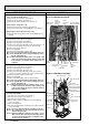
4. Disassembling the electrical parts box
(1) Remove the service panel. (See Figure 1)
(2) Remove the top panel. (See Figure 1)
(3) Disconnect the indoor/outdoor connecting wire and power
supply wire from the terminal block.
(4) Disconnect all the connectors on the controller circuit
board.
(5) Disconnect the lead wires from 3 clamps on the separator.
(6) Remove the 3 screws, screw 1, 2 and 3, that fix the
plate equipped with the outdoor controller circuit board,
and the electrical parts box, screw 1 from the front and
the screw 2 and 3 from the bottom of the electrical parts
box. (See Photo 4 and 5)
(7) Slide the plate in the direction of the arrow A and remove it.
(See Photo 4)
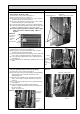
(8) Remove the lead wires from the clamp on the bottom of the
electrical parts box. (See Photo 6)
(9) Remove the 3 screws, screw 4 and 5, that fix the bottom
side of the electrical parts box and remove the bottom side
plate by sliding in the direction of the arrow B. (See Photo
6 and 7)
(10) Remove the 2 screws, screw 6 and 7, that fix the plate
equipped with the noise filter circuit board and converter
circuit board. (See Photo 8)
Note: When reassembling the electrical parts box, make
sure the wirings are correct.
OCH425F