OB369-1.qxp 04.10.14 1:37 PM Page 1 SPLIT-TYPE, AIR CONDITIONERS No. OB369 SERVICE MANUAL Wireless type Models MS-GA50VB MS-GA60VB MS-GA80VB - E1 (WH) E1 (WH) E1 (WH) CONTENTS Indication of model name MS-GA50VB MS-GA60VB MS-GA80VB - E1 E1 E1 1. TECHNICAL CHANGES ····································2 2. PART NAMES AND FUNCTIONS······················2 3. SPECIFICATION·················································4 4. NOISE CRITERIA CURVES ·······························5 5.
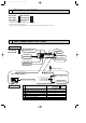
OB369-1.qxp 1 04.10.14 1:37 PM Page 2 TECHNICAL CHANGES MS-A18WV - E1 ➔MS-GA50VB - E1 MS-A24WV - E1 ➔MS-GA60VB - E1 MS-A30WV - E1 ➔MS-GA80VB - E1 1. Model name has been changed. Indication of capacity has been changed. (BTU➔kW) 2. Grille design has been changed. 3. Unit size has been changed.
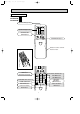
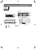
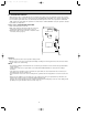
OB369-1.qxp 04.10.14 1:37 PM Page 3 REMOTE CONTROLLER MS-GA50VB - E1 MS-GA60VB - E1 MS-GA80VB - E1 Signal transmitting section Operation display section PM OPERATE/ STOP (ON/ OFF)button AM TOO ON/OFF WARM TOO COOL TEMPERATURE buttons Indication of remote controller model is on back. Open the front lid.
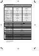
OB369-1.qxp 3 04.10.14 1:37 PM Page 4 SPECIFICATION Indoor model Function Power supply Special remarks Fan motor Electrical data Capacity Air flow(High/Med.w/Low w) K /h Power outlet A Running current A Power input W Auxiliary heater A(kW) Power factor % Fan motor current A Model Winding " resistance(at 20:) Dimensions WOHOD mm Weight kg Air direction Sound level(High/Med. w/Low w) dB Fan speed(High/Med.
OB369-1.qxp 04.10.14 1:37 PM Page 5 NOISE CRITERIA CURVES 4 MS-GA50VB - E1 MS-GA60VB - E1 FAN SPEED SPL(dB(A)) OCTAVE BAND SOUND PRESSURE LEVEL, dB re 0.0002 MICRO BAR Test conditions, Cooling : Dry-bulb temperature 27: 90 High 42 Test conditions, Cooling : Dry-bulb temperature 27: 90 Wet-bulb temperature 19: OCTAVE BAND SOUND PRESSURE LEVEL, dB re 0.
OB369-1.qxp 04.10.14 1:37 PM 5 Page 6 OUTLINES AND DIMENSIONS MS-GA50VB - E1 MS-GA60VB - E1 MS-GA80VB - E1 Unit: mm INDOOR UNIT Installation plate Indoor unit 7.5 173 98 414.5 414.5 173 47 2.5 47 255.5 1068 315 98 Wall hole [75 258 1100 Air in 5 Installation plate { Liquid line [ 6.35- 0.5m Gas line [ 12-0.43m Insulation [ 50 O.D [ 32 I.D for MS-GA50VB Liquid line [ 9.52- 0.5m Gas line [ 12-0.43m Insulation [ 50 O.D [ 32 I.
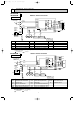
04.10.14 1:37 PM 6 Page 7 WIRING DIAGRAM MS-GA50VB - E1 MS-GA60VB - E1 INDOOR UNIT MODELS WIRING DIAGRAM TO OUTDOOR UNIT CONNECTING TB 12V CN202 BLK WHT 1 2 1 L NR11 3 2 1 BLU CN 102 CN 151 BLK GRY YLW BRN WHT RED 3 CN 121 1 3 4 C11 F11 TAB12 BRN RT12 CN112 CN201 N POWER SUPPLY CORD ~/N 230V 50Hz HIC1 1 2 2 SR141 ELECTRONIC CONTROL CN211 CN P. C. BOARD 111 CN 101 1 2 3 4 5 6 MF RT11 BRN 15 BLU 3 3 DISPLAY P. C. BOARD RECEIVER P. C.
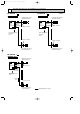
OB369-1.qxp 7 04.10.14 1:37 PM Page 8 REFRIGERANT SYSTEM DIAGRAM MS-GA50VB - E1 MS-GA60VB - E1 INDOOR UNIT INDOOR UNIT Refrigerant pipe [15.88 (with heat insulator) Refrigerant pipe [12.7 (with heat insulator) Indoor heat exchanger Indoor coil thermistor RT12 Distributor Indoor heat exchanger Flared connection Room temperature thermistor RT11 Indoor coil thermistor RT12 Distributor Flared connection Refrigerant pipe [6.35 (with heat insulator) Refrigerant pipe [6.
OB369-1.qxp 04.10.14 1:37 PM 8 Page 9 SERVICE FUNCTIONS MS-GA50VB - E1 MS-GA60VB - E1 MS-GA80VB - E1 8-1. TIMER SHORT MODE For service, set time can be shortened by short circuit of JPG and JPS on the electronic control P.C. board. The time will be shortened as follows. Set time : 1 minute ➔ 1-second Set time : 3 minute ➔ 3-second (It takes 3 minutes for the compressor to start operation. However, the starting time is shortened by short circuit of JPG and JPS.) 8-2. P.C.
OB369-1.qxp 04.10.14 1:37 PM Page 10 8-3. AUTO RESTART FUNCTION When the indoor unit is controlled with the remote controller, the operation mode, set temperature, and the fan speed are memorized by the indoor electronic control P.C.board. The “AUTO RESTART FUNCTION” sets to work the moment power has restored after power failure.Then, the unit will restart automatically. However if the unit is operated in “I FEEL CONTROL” mode before power failure, the operation is not memorized.
OB369-1.qxp 04.10.14 1:37 PM 9 Page 11 TROUBLESHOOTING MS-GA50VB - E1 MS-GA60VB - E1 MS-GA80VB - E1 9-1. Cautions on troubleshooting 1. Before troubleshooting, check the following: (1) Check the power supply voltage. (2) Check the indoor/outdoor connecting wire for mis-wiring. 2. Take care the following during servicing.
OB369-1.qxp 04.10.14 1:37 PM Page 12 9-2. Instruction of troubleshooting Start Indoor unit operates. Outdoor unit doesn't operate. Outdoor unit operates in only Test Run operation. Check room temperature thermistor. Refer to 9-6. "Test point diagram and voltage". Outdoor unit doesn't operate even in Test Run operation. Refer to "Check of outdoor unit". Indoor unit operates. Outdoor unit doesn't operate normally. Outdoor unit doesn't stop even if indoor unit stops.
OB369-1.qxp 04.10.14 1:37 PM Page 13 9-3. Troubleshooting check table • The following indication applies regardless of shape of the indicator. Operation Indicator Lighted Not lighted · Flashing of the OPERATION INDICATOR lamp (on the left-hand side) indicates possible abnormalities. · The OPERATION INDICATOR lamp (on the left-hand side) is lighted during normal operation. Before taking measures, make sure that the symptom reappears, for accurate troubleshooting. Self check table No.
OB369-1.qxp 04.10.14 1:37 PM Page 14 9-4. Trouble criterion of main parts MS-GA50VB - E1 MS-GA60VB - E1 MS-GA80VB - E1 Figure Part name Room temperature thermistor(RT11) Check method and criterion Measure the resistance with a tester.
OB369-1.qxp 04.10.14 1:37 PM Page 15 9-5. Troubleshoot flow When OPERATION INDICATOR lamp flashes 3-time. Indoor fan motor doesn’t operate. A Check of indoor fan motor Turn OFF the power supply. Check connector CN211 visually. No Are lead wires connected? Yes Is soldered point of the connector correctly soldered? No Resolder it. Yes Reconnect the lead wires. Disconnect lead wires from connector CN211 on the indoor electronic control P.C. board. Measure resistance between lead wires No.1 and No.
OB369-1.qxp 04.10.14 1:37 PM Page 16 The unit doesn’t operate with the remote controller. Also, the OPERATION INDICATOR lamp doesn’t light up by pressing the EMERGENCY OPERATION switch. C Check of indoor electronic control P.C. board Check the both “parts side” and “pattern side” of indoor electronic control P.C. board visually. Varistor (NR11) Turn OFF the power supply. Remove indoor fan motor connector CN211 and vane motor connector CN151 from the indoor electronic control P.C.
OB369-1.qxp 04.10.14 1:37 PM Page 17 When OPERATION INDICATOR lamp flashes ON and OFF in every 0.5-second. Outdoor unit doesn’t operate. D How to check mis-wiring MS-GA80VB w Short circuit of JPG and JPS on the indoor electronic control P.C. board enables self -check to be displayed in 3 seconds. Start • Turn ON the power supply. (indoor/ outdoor unit) • Press once EMERGENCY OPERATION switch. After 3 minutes, mis-wiring is indicated (0.5-second ON, 0.
OB369-1.qxp 04.10.14 1:37 PM Page 18 9-6. Test point diagram and voltage MS-GA50VB - E1 MS-GA60VB - E1 MS-GA80VB - E1 Indoor electronic control P.C. board Fan motor power supply } Power supply input 230V AC + Fuse (F11) 250V AC 3.15A } 5V DC Room temperature thermistor(RT11) Indoor coil thermistor(RT12(main)) R132 MS-GA80VB Indoor coil thermistor(RT13(sub)) Emergency operation switch Timer short mode point (JPS, JPG) (Refer to page 9.) + } Receiver P.C.
OB369-1.qxp 04.10.14 1:37 PM 10 Page 19 DISASSEMBLY INSTRUCTIONS <"Terminal with lock mechanism" Detaching points> In case of terminal with lock mechanism, detach the terminal as shown below. There are two types ( Refer to (1) and (2)) of the terminal with lock mechanism. The terminal with no lock mechanism can be removed by pulling it out. Check the shape of the terminal and work. (1) Slide the sleeve and check if there is a locking lever or not.
OB369-1.qxp 04.10.14 1:37 PM Page 20 OPERATING PROCEDURE PHOTOS 3. Removing the electrical box (1) Remove the front panel. (Refer to 1.) (2) Remove the electrical cover. (Refer to 2.) (3) Disconnect the connector of the indoor coil thermistor. (4) Disconnect the motor connector (CN211 and CN121) and the vane motor connector (CN151) on the electronic control P.C. board. (5) Remove the screws of ground wire. (6) Remove the fan motor lead wire and indoor coil thermistor from the electrical box.
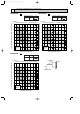
OB369-1.qxp 04.10.14 1:37 PM 11 Page 21 PARTS LIST MS-GA50VB - E1 (WH) MS-GA60VB - E1 (WH) MS-GA80VB - E1 (WH) 11-1. INDOOR UNIT STRUCTURAL PARTS 11-2. INDOOR UNIT HEAT EXCHANGER 1 2 10 3 8 4 CATCH Optional parts (See page 23.) 5 SCREW CAP 11 12 6 7 11-1. INDOOR UNIT STRUCTURAL PARTS Part number that is circled is not shown in the illustration. No. 1 2 3 4 5 6 7 8 9 Part No.
OB369-1.qxp 04.10.14 1:37 PM Page 22 MS-GA50VB - E1 (WH) MS-GA60VB - E1 (WH) MS-GA80VB - E1 (WH) 11-3. INDOOR UNIT FUNCTIONAL PARTS AND ELECTRICAL PARTS 1 20 11-4. ACCESSORY AND REMOTE CONTROLLER 19 23 24 2 3 SLEEVE BEARING 4 11 18 12 ROOM TEMPERATURE THERMISTOR 5 6 14 13 10 7 FUSE 8 9 VARISTOR 17 15 16 11-3. INDOOR UNIT FUNCTIONAL PARTS AND ELECTRICAL PARTS Part numbers that are circled are not shown in the illustration. No.
OB369-1.qxp 04.10.14 1:37 PM 12 Page 23 OPTIONAL PARTS AIR CLEANING FILTER ● AIR CLEANING FILTER removes fine dust of 0.01 micron from air by means of static electricity. ● Normal life of AIR CLEANING FILTER is 4 months. However, when it becomes dirty, replace it as soon as possible. ● Clogged AIR CLEANING FILTER may reduce the air conditioner capacity or cause frost on the air outlet. ● DO NOT reuse AIR CLEANING FILTER even if it is washed.
OB369-1.qxp 04.10.14 1:37 PM Page 24 HEAD OFFICE: MITSUBISHI DENKI BLDG.,2-2-3, MARUNOUCHI, CHIYODA-KU, TOKYO100-8310, JAPAN C Copyright 2004 MITSUBISHI ELECTRIC ENGINEERING CO.,LTD Distributed in Oct. 2004. No.OB369 6 Made in Japan New publication, effective Oct. 2004 Specifications subject to change without notice.