
Service manual


18
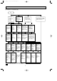
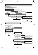
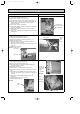
9-6. Test point diagram and voltage
MS-GA50VB - MS-GA60VB - MS-GA80VB -
Indoor electronic control P.C. board
E1E1E1
Fan motor power supply
Fuse (F11)
250V AC 3.15A
}
Power supply input
230V AC
+
}
5V DC
Indoor coil
thermistor(RT12(main))
Timer short mode point
(JPS, JPG)
(Refer to page 9.)
Emergency operation
switch
+
}
12V DC
Indoor coil thermistor(RT12(main), RT13(sub))
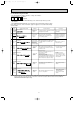
Room temperature thermistor (RT11)
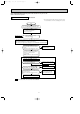
Resistance(k")
Room temperature ther-
mistor(RT11)
Release of “Auto restart function”
Solder jumper wire to JR07.
(Refer to page 10.)
MS-GA80VB
Indoor coil
thermistor(RT13(sub))
R132
Receiver P.C. board
OB369-1.qxp 04.10.14 1:37 PM Page 18