OB266--1.qxp 01.4.13 10:31 AM Page 1 Note: ●Refer to OB196 REVISED EDITION-A for the details of MCFH-24NV- EA and MUCFH-24NV- EA . FLOOR AND CEILING TYPE AIR CONDITIONERS No. OB266 SERVICE MANUAL Wireless type Models MCFH-24NV- EB (WH) ·MUCFH-24NV- EB (When installed on the floor) CONTENTS (When installed on the ceiling) 1. TECHNICAL CHANGES ····································2 2. PART NAMES AND FUNCTIONS······················2 3.
OB266--1.qxp 1 01.4.13 10:31 AM Page 2 TECHNICAL CHANGES MCFH-24NV - →MCFH-24NV - EA EB 1. Only model name has changed. MUCFH-24NV - EA →MUCFH-24NV - EB 1. Ball valve has changed to stop valve. 2. Deicer P.C. board has changed.
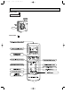
OB266--1.qxp 01.4.
OB266--1.qxp 3 01.4.13 10:31 AM Page 4 SPECIFICATION Fan motor Electrical data Capacity Indoor model Function Power supply Capacity kW Air flow(High) K /h Dehumidification L/h Power outlet A Running current A Power input W Auxiliary heater A(kW) Power factor % Starting current A Fan motor current A Coefficient of performance(C.O.P) Model Winding resistance(at20:) " Cooling Heating Single phase 220 - 240 V, 50Hz 6.0 6.2 840 3.1 25 12.5-11.7 2,720-2,750 99-98 11.7-11.3 2,540-2,650 98-98 59 0.
OB266--1.qxp 01.4.13 10:31 AM 4 Page 5 OUTLINES AND DIMENSIONS EB Unit: mm 114 MCFH-24NV - INDOOR UNIT 80.8 906 16 112.8 (When installed on the floor) 93 77 m o (When installed on the ceiling) rm 113 180 1100 Gas line {15.88 17.5 56 Liquid line {9.52 160 50cm or more 42.5 100cm or more 170 ore 5 143 50c 616.
Handle for moving 95 100 For 10 units or less Rear piping hole 10 138 200 Rear fresh air intake 23 Side air intake 1000 7 295(11-5/8) Outlet guide installation hole Handle for moving 24(1) 33 524 Drain hole 40 524 870(34-1/4) Drain hole 2-12o23 Oval holes (standard bolt M10) 302 Air outlet Service panel 10 Note:Allow adequate upper clearance 10 500 Front opening 12 R6 Service space 0 65 120 60 Knock out holes for power line 2-[27 Standard bolt length EB Front right pip
OB266--1.qxp 01.4.13 10:31 AM 5 Page 7 WIRING DIAGRAM MODEL MCFH-24NV- INDOOR UNIT EB TB GRN/YLW N L BLU WHT 3 2 1 CN201 N BLU TO OUTDOOR UNIT CONNECTING 2 WHT 4 3 52C TRANS F11 BRN CN CN 101 113 3 RED CN 151 RT12 WHT ORN RED BLK YLW BLU BRN LDCOM LDC11 C11 LDC12 LDFH SR144 LDFM SR143 LDFL SR142 LDFVL SR141 ELECTRONIC CONTROL P.C BOARD 1 2 3 4 5 6 7 8 WHT ORN RED BLK YLW BLU BRN MF GRN/YLW 6 4 MV 5 SW/THERMO P.C.BOARD DISP/ RECEIVER P.C.
OB266--1.qxp 6 01.4.13 10:31 AM Page 8 REFRIGERANT SYSTEM DIAGRAM MCFH-24NV- MUCFH-24NV- EB INDOOR UNIT Indoor heat exchanger Refrigerant pipe [15.88 (Option) (with heat insulator) OUTDOOR UNIT 4-way valve Muffler Stop valve (with service port) Distributor EB Outdoor heat exchanger Strainer Flared connection Coil temperature thermistor RT12 Compressor Accumulator Room temperature thermistor RT11 Capillary tube [3.0o[1.
OB266--1.qxp 01.4.13 10:31 AM 7 Page 9 PERFORMANCE CURVES The standard data contained in these specifications apply only to the operation of the air conditioner under normal condition. Operating conditions vary according to the areas where these units are installed. The following information has been provided to clarify the operating characteristics of the air conditioner under the conditions indicated by the performance curve.
01.4.13 10:31 AM Page 10 OUTDOOR LOW PRESSURE AND OUTDOOR UNIT CURRENT COOL operation 1 Both indoor and outdoor units are under the same temperature/humidity condition. Dry Bulb temperature (˚C) 20 25 30 Relative humidity (%) 50 60 70 2 Air flow should be set at MAX.. 3 The unit of pressure has been changed to MPa on the international system of units(SI unit system). The converted score against the traditional unit system can be gotten according to the formula below. f • G) 1(MPa • G) =10.
OB266--1.qxp 01.4.13 10:31 AM 8 Page 11 MICROPROCESSOR CONTROL MCFH-24NV - EB MUCFH-24NV - EB WIRELESS REMOTE CONTROLLER Once the operation mode are set, the same operation mode can be repeated by simply turning the OPERATE/STOP button ON. Indoor unit receives the signal with a beep tone. When the system turns off, 3-minute time delay will operate to protect system from overload and compressor will not restart for 3 minutes. 8-1.
OB266--1.qxp 01.4.13 10:31 AM Page 12 (4) The initial set temperature is decided by the initial room temperature.
OB266--1.qxp 01.4.13 10:31 AM Page 13 — COOL mode of “I FEEL CONTROL” — NOTE : Coil frost prevention during COOL mode of “I FEEL CONTROL” There are two types of controls in coil frost prevention as follows. 1 Temperature control When the indoor coil thermistor RT12 reads -1°C or below, the coil frost prevention mode starts immediately. However the coil frost prevention will not work for 5 minutes after the compressor starts.
OB266--1.qxp 01.4.13 10:31 AM Page 14 Operation time chart Example ON 1st ON Thermostat OFF OFF Indoor fan OFF OFF ON Outdoor fan compressor OFF ON OFF OFF ON ON ON 8 min. ON OFF 3 min. 4 min. 1 min. NOTE ● Coil frost prevention during DRY mode of “I FEEL CONTROL” The operation is same as that of coil frost prevention during COOL mode of “I FEEL CONTROL”. However the indoor fan speed becomes the set speed or Low. — HEAT mode of “I FEEL CONTROL” — 1.
OB266--1.qxp 01.4.13 10:31 AM Page 15 2. High pressure protection During heating operation, the outdoor fan motor is controlled by the indoor coil thermistor RT12 temperature for excess rise protection of compressor discharge pressure.
OB266--1.qxp 01.4.13 10:31 AM Page 16 (3) Defrosting time chart Defrost thermistor RT61 3.1: or more -3: or less Outdoor 52C relay (Compressor) ON OFF X62 (R.V.coil) SR61 Outdoor fan Defrost counter 15 sec. ON OFF 30 sec. 30 sec. 5 sec. ON OFF ON OFF Max. 10 min. NOTE ON Indoor fan Very Low OFF Position 1 Indoor vane Set Position NOTE ● When the indoor coil thermistor reads above 18°C, indoor fan operates at Very Low for 30 seconds.
OB266--1.qxp 01.4.13 10:31 AM Page 17 4. 4-way valve control Heating · · · · · ON Cooling · · · · · OFF Dry · · · · · · · · OFF NOTE: The 4-way valve reverses for 5 seconds right before start-up of the compressor. Compressor 4-way valve Outdoor fan 8-2. COOL ( (COOL / DRY) (HEAT) 5 sec. 5 sec. ON OFF ON OFF ON OFF )OPERATION (1) Press OPERATE/STOP button. OPERATION INDICATOR lamp of the indoor unit turns on with a beep tone. (2) Select COOL mode.
OB266--1.qxp 01.4.13 10:31 AM Page 18 8-5. AUTO VANE OPERATION (1) Vane motor drive This series is equipped with a stepping motor for the vane. The rotating direction, speed, and angle of the motor are controlled by pulse signals (approx. 12V, transmitted from indoor microprocessor.) (2) Each time the VANE CONTROL button is pressed, angle of horizontal vane is changed in sequence, from 1,2,3,4,5 to AUTO.
OB266--1.qxp 01.4.13 10:31 AM Page 19 8-6. TIMER OPERATION 1. How to set the timer (1) Press OPERATE/STOP button to start the air conditioner. (2) Check that the current time is set correctly. NOTE : Timer operation will not work without setting the current time. Initially “AM0:00” blinks at the current time display of TIME MONITOR, so set the current time correctly with CLOCK SET button. (3) Press ON-TIMER, OFF-TIMER button to select the operation. w➝| button ...
OB266--1.qxp 01.4.13 10:31 AM Page 20 8-7. EMERGENCY-TEST OPERATION When the remote controller is missing, has failed or the batteries run down, press the EMERGENCY OPERATION switch on the front of the indoor unit. The unit will start and the OPERATION INDICATOR lamp will light. The first 30 minutes of operation will be the test run operation. This operation is for servicing. The indoor fan runs at high speed and the system is in continuous operation.
OB266--1.qxp 01.4.13 10:31 AM 9 Page 21 SERVICE FUNCTIONS MCFH-24NV - EB 9-1. TIMER SHORT MODE For service, set time can be shortened by short circuit of JPG and JPS on the electronic control P.C. board. The time will be shortened as follows. 3-minute time delay : 3-minute → 3-second. AUTO START : 1 hour → 1-minute Short the connector during the timer mode. AUTO STOP : 1 hour → 1-minute } 9-2. P.C.
OB266--1.qxp 01.4.13 10:31 AM Page 22 9-3. COMPULSORY DEFROSTING MODE FOR SERVICE By short circuit of the connector JPG1 and R871 on the outdoor deicer P.C. board, defrosting mode can be accomplished regardless of the defrost interval restriction. See Page 33. Defrost thermistor RT61 must be below -3:. 9-4. DEFROST TERMINATION CHANGE when the JRF wire of the deicer P.C. board is cut, the defrost interval time will be changed.(See page 33.) when the JRG wire of the deicer P.C.
OB266--1.qxp 01.4.13 10:31 AM 10 Page 23 TROUBLESHOOTING MCFH-24NV - EB MUCFH-24NV - EB 10-1. Cautions on troubleshooting 10-1-1. Before troubleshooting, check the followings: 1) Check the power supply voltage. 2) Check the indoor/outdoor connecting wire for mis-wiring. 10-1-2. Take care the followings during servicing. 1) Be sure to unplug the power cord before removing the air inlet grille, the front panel, the cabinet, the top panel, and the electronic control P.C. boards.
OB266--1.qxp 01.4.13 10:55 AM Page 24 10-2. Instruction of troubleshooting MCFH-24NV- EB Start Indoor unit operates. Outdoor unit doesn't operate. Outdoor unit operates in only Test Run operation. Check room temperature thermistor. Refer to "Test point diagram and voltage" on page 32 or 33. Flash on and off at 0.5second intervals Cause: Indoor/ Outdoor unit • Mis-wiring Refer to G "How to check miswiring and serial signal error (When outdoor unit doesn't work)" on page 30.
OB266--1.qxp 01.4.13 10:31 AM Page 25 10-2-1. Troubleshooting check table OPERATION INDICATOR lamp Before taking measures, make sure that the symptom reappears, for accurate troubleshooting. Self check table No. Abnormal point Operation indicator lamp Symptom 0.5-second ON Detection method After 3 minutes from power supply turns ON, when serial signal is not received. • Refer to G "How to check mis-wiring and serial signal error" on page 30.
OB266--1.qxp 01.4.13 10:31 AM Page 26 10-2-2. Trouble criterion of main parts MCFH-24NV - EB MUCFH-24NV - EB Check method and criterion Part name Room temperature thermistor (RT11) Indoor coil thermistor (RT12) Defrost thermistor (RT61) Ambient temperature thermistor (RT63) Figure Measure the resistance with a tester. (Part temperature 10°C ~ 30°C) Normal Abnormal 8kΩ ~ 20kΩ Opened or short-circuited Measure the resistance with a tester.
OB266--1.qxp 01.4.13 10:31 AM Page 27 A Check of indoor fan motor Turn OFF power supply. Check connector (Fan motor) visually. Indoor fan does not operate. No No Yes Are lead wires connected? Is soldered point normal? Yes Reconnect the lead wires. Resolder it. Disconnect lead wires from connector (Fan motor). Measure resistance between lead wires No.1 and No.4 and then No.3 and No.4 of the fan motor.
OB266--1.qxp 01.4.13 10:31 AM Page 28 C Check of indoor electronic control P.C. board The unit doesn’t operate with the remote controller. Also, the OPERATION INDICATOR lamp doesn’t light up by pressing the EMERGENCY OPERATION switch. Replace the fuse. Yes No Is fuse(F11)blown? Check both “parts side”and “pattern side” of indoor electronic control P.C. board visually. Trouble of the indoor electronic control P.C. board. Be sure to check both fuse and varistor in any case.
OB266--1.qxp 01.4.13 10:31 AM Page 29 E Check of outdoor unit Compressor and / or outdoor fan motor doesn’t stop. 1 Turn OFF the power supply. 2 After 30 seconds, turn ON the power supply again. 3 Operate the unit in COOL or HEAT mode by pressing the EMERGENCY OPERATION switch. 4 Operate the unit for 1 minute or more and stop it by pressing the EMERGENCY OPERATION switch again.
OB266--1.qxp 01.4.13 10:31 AM Page 30 G How to check mis-wiring and serial signal error (when outdoor unit doesn’t work) Outdoor unit doesn’t operate. Start ❈1 Short circuit of JPG and JPS on the indoor electronic control P.C. board enables self-check to be displayed in 3 seconds. 1. Turn OFF the power supply. 2. Turn ON the power supply. 3. Press the EMERGENCY OPERATION switch. 3 min.
OB266--2.qxp 01.4.13 10:31 AM Page 31 H Check of outdoor thermistor Thermistors in the outdoor unit are abnormal. w Disconnect the connectors CN661 and/or CN662 from the deicer P.C. board. (Check the characteristics of each thermistor.) Defrost thermistor(RT61) Measure resistance between CN 661 1 and 2. Replace the deicer P.C. board. Does the resistance Yes of thermistor have the characteristics on page 33? Turn OFF the power supply. No Reconnect CN661 and CN662.
OB266--2.qxp 01.4.13 10:31 AM Page 32 TEST POINT DIAGRAM AND VOLTAGE MCFH-24NV - EB Indoor electronic control P.C. board Fan motor power supply AC 220 - 240V Very Low Med. 7 5 Low High 6 4 3 2 1 8 Fuse AC250V 3.
OB266--2.qxp 01.4.13 10:31 AM Page 33 MUCFH-24NV - EB Outdoor deicer P.C. board Defrost thermistor (RT61) Ambient temperature thermistor (RT63) 100 Resistance(k") 90 80 70 60 50 40 30 20 10 0 -20 -10 0 10 20 30 40 Temperature(:) CN661 1-2 Defrost thermistor (RT61) (Refer to page 31.) CN662 3-4 Ambient temperature thermistor (RT63) (Refer to page 31.) Fan motor connector Varistor (CN711) (NR62) coil } R.V. (CN721) Defrost interval time short pin(JPG1, R871) (Refer to page 22.) + } 12V DC Fuse 3.
OB266--2.qxp 11 01.4.13 10:31 AM Page 34 DISASSEMBLY INSTRUCTIONS ”w” shows the terminals with a lock mechanism, so they cannot be removed when you pull the lead wire. Be sure to pull the wire by pushing the locking lever (project part) of the terminal with a finger. 1Slide the sleeve. 2Pull the wire while pushing the locking lever. 11-1.MCFH-24NV- EB INDOOR UNIT OPERATING PROCEDURE PHOTOS 1. Removing the electronic control P. C . board. (1) Pull out the upper part of the grill.
OB266--2.qxp 01.4.13 10:31 AM Page 35 OPERATING PROCEDURE PHOTOS 3. Removing the indoor heat exchanger. Photo 5 (1) Remove the grill. (Refer to 1(1) (2)) (2) Remove the screws on both side and in front of the front panel. (Photo 5) (3) Remove the screws of the nozzle assembly. (Photo 6) (4) Remove the electronic box . (Refer to 1) (5) Remove the indoor fan motor . (Refer to 2) (6) Remove the screws of the motor support . (7) Remove the fan casing .
OB266--2.qxp 01.4.13 10:32 AM Page 36 11-2. MUCFH-24NV - EB OUTDOOR UNIT OPERATING PROCEDURE PHOTOS 1. Removing the cabinet (1) Remove the screws of the top panel and the top panel. (2) Remove the screw of the service panel. To remove the service panel, pull it down toward you and unhook the catches on the both sides. (3) Remove the screw of the cover panel. To remove the cover panel. (4) Remove the screws of the cabinet. Open the cabinet to a 45-degree angle.
OB266--2.qxp 01.4.13 10:32 AM Page 37 OPERATING PROCEDURE PHOTOS 4. Removing the heat exchanger and compressor (1) Remove the screws of the rear panel. Remove the screws of the valve bed and the valve bed. (The valve bed is fixed by the catches on the right and left sides. Lift it to remove.) Open the rear panel to the rear to remove. NOTE : All panels are fixed by catches, and must be removed by up and down. (2) Remove the screws of the side panel and the side panel.
OB266--2.qxp 12 01.4.13 10:32 AM Page 38 PARTS LIST MCFH-24NV - EB 12-1. INDOOR UNIT STRUCTURAL PARTS 1 14 15 13 2 12 11 3 10 9 6 5 7 8 4 Part number that are circled is not shown in the illustration. No. Part No.
OB266--2.qxp 01.4.13 10:32 AM Page 39 MCFH-24NV - EB (WH) 12-2. INDOOR UNIT ELECTRICAL PARTS MCFH-24NV- EB (WH) 12-3. ACCESSORY AND REMOTE CONTROLLER PARTS 11 6 5 7 8 12 1 4 2 3 12-2. INDOOR UNIT ELECTRICAL PARTS Part numbers that are circled is not shown in the illustration. Symbol in Wiring Diagram Q'ty/unit MCFH-24NV- EB No. Part No.
OB266--2.qxp 01.4.13 10:32 AM Page 40 MUCFH-24NV - EB 12-4.
OB266--2.qxp 01.4.13 10:32 AM Page 41 MUCFH-24NV - EB 12-4. OUTDOOR UNIT STRUCTURAL PARTS, ELECTRICAL PARTS AND FUNCTIONAL PARTS Part numbers that are circled are not shown in the illustration. Symbol NO. Part No. Part Name Q'ty/unit Remarks in Wiring Diagram MUCFH-24NV- 1 E02 214 297 TOP PANEL 2 E02 540 309 AMBIENT TEMPERATURE THERMISTOR 3 E02 444 961 4-WAY VALVE 4 E02 529 490 R.V.
OB266--2.qxp 13 01.4.13 10:32 AM Page 42 OPTIONAL PARTS 13-1. REFRIGERANT PIPES The air conditioner has flared connections its indoor and outdoor sides. Please use the optional extension pipe as follows. Pipe size O.D.mm Applied unit Models Pipe length Cross-section MCFH-24NV - EB MAC-860PI MAC-861PI MAC-862PI MAC-863PI MAC-864PI 3m 5m 7m 10m 15m Insulation D A-Gas B-liquid C {15.88 {9.52 {31 Additional refrigerant charge R22(g) 0 {27 195 520 13-2.
OB266--2.qxp 01.4.
OB266--2.qxp 01.4.13 10:32 AM Page 44 HEAD OFFICE: MITSUBISHI DENKI BLDG.,2-2-3, MARUNOUCHI, CHIYODA-KU, TOKYO100-8310, JAPAN C Copyright 2001 MITSUBISHI ELECTRIC ENGINEERING CO.,LTD Distributed in Apr. 2001. No.OB266 223 Made in Japan New publication, effective Apr. 2001 Specifications subject to change without notice.