OBH488A-1.qxp 07.9.25 11:33 AM Page 1 Revision A: SPLIT-TYPE, HEAT PUMP AIR CONDITIONERS • 3. SPECIFICATION has been corrected. • 10-5. TROUBLE CRITERION OF MAIN PARTS has been corrected. Please void OBH488. INDOOR UNIT SERVICE MANUAL No. OBH488 REVISED EDITION-A Wireless type Models MSZ-FD25VA MSZ-FD25VAS MSZ-FD35VA MSZ-FD35VAS E1 E1 E1 E1 Outdoor unit service manual MUZ-FD·VA Series(OBH489) MXZ-A·VA Series (OB377) MXZ-8A140A (OC316) CONTENTS 1.
OBH488A-1.qxp 07.9.25 11:33 AM Page 2 Revision A: • 3. SPECIFICATION has been corrected. • 10-5. TROUBLE CRITERION OF MAIN PARTS has been corrected.
OBH488A-1.qxp 1 07.9.25 11:33 AM Page 3 TECHNICAL CHANGES MSZ-FD25VA - E1 MSZ-FD25VAS - E1 MSZ-FD35VA - E1 MSZ-FD35VAS - E1 1.
OBH488A-1.qxp 2 07.9.
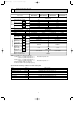
OBH488A-1.qxp 07.9.25 11:33 AM 3 Page 5 SPECIFICATION Indoor model MSZ-FD25VA Electrical data Power input ✽1 Cooling Heating Running current ✽1 Cooling Heating Fan motor current ✽1 Cooling Heating Fan motor model Dimensions WOHOD Weight Color Air direction Air flow Cooling (Super High) Heating Air flow Cooling (High/Med./Low) Heating Sound level Cooling (Super High) Heating Sound level Cooling (High/Med./Low) Heating Fan speed Cooling (Super High) Heating Fan speed Cooling (High/Med.
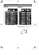
OBH488A-1.qxp 4 07.9.25 11:33 AM Page 6 NOISE CRITERIA CURVES MSZ-FD25VA MSZ-FD25VAS MSZ-FD35VA MSZ-FD35VAS FAN SPEED FUNCTION Super High SPL(dB(A)) LINE FAN SPEED FUNCTION COOLING Super High 42 43 HEATING 90 OCTAVE BAND SOUND PRESSURE LEVEL, dB re 0.0002 MICRO BAR OCTAVE BAND SOUND PRESSURE LEVEL, dB re 0.
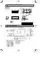
07.9.25 11:33 AM 5 Page 7 OUTLINES AND DIMENSIONS MSZ-FD25VA MSZ-FD25VAS MSZ-FD35VA MSZ-FD35VAS Unit : mm 11 X 20 Oblong hole 64 21.5 231.5 253 225 6.5 155 345 54 330 42 155 Indoor unit 3 41 47 254 798 785 225 64 Installation plate 211.5 11 X 26 Oblong hole 212.5 OBH488A-1.
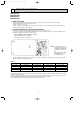
OBH488A-1.qxp 7 07.9.25 11:33 AM Page 8 REFRIGERANT SYSTEM DIAGRAM MSZ-FD25VA MSZ-FD25VAS MSZ-FD35VA MSZ-FD35VAS Unit : mm Refrigerant pipe [9.52 (with heat insulator) Indoor heat exchanger Indoor coil thermistor RT12 (main) Flared connection Indoor coil thermistor RT13 (sub) Room temperature thermistor RT11 Flared connection Refrigerant pipe [6.
OBH488A-1.qxp 07.9.25 11:33 AM 8 Page 9 SERVICE FUNCTIONS MSZ-FD25VA MSZ-FD25VAS MSZ-FD35VA MSZ-FD35VAS 8-1. TIMER SHORT MODE For service, set time can be shortened by short circuit of JPG and JPS on the electronic control P.C. board. The time will be shortened as follows. (Refer to 10-7.) Set time : 1-minute ➔ 1-second Set time : 3-minute ➔ 3-second (It takes 3 minutes for the compressor to start operation. However, the starting time is shortened by short circuit of JPG and JPS.) 8-2. P.C.
OBH488A-1.qxp 07.9.25 11:33 AM Page 10 8-3. AUTO RESTART FUNCTION When the indoor unit is controlled with the remote controller, the operation mode, the set temperature, and the fan speed are memorized by the indoor electronic control P.C. board. “AUTO RESTART FUNCTION” automatically starts operation in the same mode just before the shutoff of the main power. Operation 1 If the main power has been cut, the operation settings remain.
OBH488A-1.qxp 9 07.9.
OBH488A-1.qxp 07.9.25 11:33 AM 9-1. COOL ( Page 12 ) OPERATION (1) Press OPERATE/STOP(ON/OFF) button. POWER lamp of the indoor unit turns on with a beep tone. (2) Select COOL mode with OPERATION SELECT button. (3) Press TEMPERATURE buttons (TOO WARM or TOO COOL button) to select the desired temperature. The setting range is 16 ~ 31 °C. 1. Coil frost prevention The compressor operational frequency is controlled by the temperature of the indoor heat exchanger to prevent the coil from frosting.
OBH488A-1.qxp 07.9.25 11:33 AM Page 13 NOTE 2 FOR MULTI SYSTEM AIR CONDITIONER OUTDOOR UNIT : MXZ series Multi system air conditioner can connect two or more indoor units with one outdoor unit. •When you try to operate two or more indoor units with one outdoor unit simultaneously, one for the cooling and the others for heating, the operation mode of the indoor unit that operates earlier is selected. The other indoor units cannot operate, indicating as shown in the figure below.
OBH488A-1.qxp 07.9.25 11:33 AM Page 14 (7) SWING ( ) mode By selecting SWING mode with VANE CONTROL button, the horizontal vane swings vertically. (8) Cold air prevention in HEAT operation The horizontal vane position is set to Upward. NOTE : When 2 or more indoor units are operated with multi outdoor unit, even if any indoor unit turns thermostat off, this control doesn’t work in the indoor unit. (9) To change the airflow direction not to blow directly onto your body.
OBH488A-1.qxp 07.9.25 11:33 AM Page 15 9-6. i-see CONTROL OPERATION The sensors constantly measure the room and floor/wall temperatures to automatically adjust to the set temperature by estimating the temperature actually perceived by a person inside the room (“sensory temperature”). Advantages · The air inside the room is conditioned quickly to a comfortable condition. · The room will not become too cold or hot even when the air conditioner is kept on for a long period.
OBH488A-1.qxp 07.9.25 11:33 AM Page 16 ●Indoor unit installation location and air-conditioning area Installed at left LEFT Installed at center RIGHT LEFT Installed at right RIGHT LEFT RIGHT · Be sure to set the slide switch inside the remote controller to an appropriate position in accordance with the installed position of the indoor unit. If the switch is not set correctly, the air conditioner may not function properly. (Refer to "Remote controller in SERVICE FUNCTIONS".
OBH488A-1.qxp 07.9.25 11:33 AM Page 17 Operation and operating range i-see sensor moves 30 degrees from the center in both right and left side. i-see Sensor turning to the left i-see Sensor turning to the center i-see Sensor turning to the right i-see Sensor operates as follows in accordance with AREA setting made with the remote controller. “AUTO” in AREA setting; first turning to the LEFT for adjusting the position then..... CENTER RIGHT CENTER LEFT CENTER......
OBH488A-1.qxp 07.9.25 11:33 AM 9-9. CLEAN ( Page 18 ) OPERATION • When CLEAN operation is set, it performs for 40 minutes when unit is stopped after COOL/DRY operation. CLEAN operation performs when: COOL is operated more than 3 minutes / DRY is operated more than 6 minutes. • The horizontal vane is slightly opened and the fan is stopped for the first 15 minutes. Then, the horizontal vane is set to higher than angle 1 and the fan is operaed for 25 minutes. 9-10. TIMER OPERATION 1.
OBH488A-1.qxp 07.9.25 11:33 AM Page 19 9-11. EMERGENCY/TEST OPERATION In case of test run operation or emergency operation, use EMERGENCY OPERATION switch on the right side of the indoor unit. Emergency operation is available when the remote controller is missing, has failed or the batteries of the remote controller run down. The unit will start and AREA lamp will light. The first 30 minutes of operation is the test run operation. This operation is for servicing.
OBH488A-1.qxp 10 07.9.25 11:34 AM Page 20 TROUBLESHOOTING MSZ-FD25VA MSZ-FD25VAS MSZ-FD35VA MSZ-FD35VAS 10-1. CAUTIONS ON TROUBLESHOOTING 1. Before troubleshooting, check the following 1) Check the power supply voltage. 2) Check the indoor/outdoor connecting wire for miswiring. 2.
OBH488A-1.qxp 07.9.25 11:34 AM Page 21 10-2. FAILURE MODE RECALL FUNCTION Outline of the function This air conditioner can memorize the abnormal condition which has occurred once. Even though LED indication listed on the troubleshooting check table (10-4.) disappears, the memorized failure details can be recalled. This mode is very useful when the unit needs to be repaired for the abnormality which doesn't recur. 1.
OBH488A-1.qxp 07.9.25 11:34 AM Page 22 2. Flow chart of PLASMA operation failure mode recall function Operational procedure The plasma electrode unit might be abnormal. Confirm if plasma electrode unit is abnormal according to the following procedures. Confirm that the remote controller is in the failure mode recall function. With the remote controller headed towards the indoor unit, press TOO COOL or TOO WARM button to adjust the set temperature to 23 :.
OBH488A-1.qxp 07.9.25 11:34 AM Page 23 4. Indoor unit failure mode table POWER lamp Abnormal point (Failure mode) Condition Correspondence Normal — — Not lighted 1-time flash every 0.5-second Room temperature thermistor The room temperature thermistor short or open circuit is detected every 8 seconds during operation. Refer to the characteristics of the room temperature thermistor (10-7.). 2-time flash 2.
OBH488A-1.qxp 07.9.25 11:34 AM Page 24 10-3. INSTRUCTION OF TROUBLESHOOTING w"Test Run operation" means the operation within 30 minutes after EMERGENCY OPERATION switch is pressed. Start Indoor unit operates. Outdoor unit doesn't operate. Indoor unit operates. Outdoor unit doesn't operate normally. Indoor unit doesn't receive the signal from remote controller. If blinking of OPERATION INDICATOR lamp cannot be checked, it can be checked with failure mode recall function.
OBH488A-1.qxp 07.9.25 11:34 AM Page 25 10-4. TROUBLESHOOTING CHECK TABLE Before taking measures, make sure that the symptom reappears for accurate troubleshooting. When the indoor unit has started operation and the following detection method has detected an abnormality (the first detection after the power ON), the indoor electronic control P.C. board turns OFF the indoor fan motor with OPERATION INDICATOR lamp flashing. L AREA R POWER Lighted CLEAN PLASMA Blinking Not lighted No.
OBH488A-1.qxp 07.9.25 11:34 AM L AREA R No. Abnormal point Page 26 POWER CLEAN PLASMA Operation indicator lamp All lamps flash at the same time. Attachment 0.5-second ON of the 1 horizontal vane 0.5-second OFF L AREA R No. 1 Abnormal point Operation indicator lamp Abnormal point PLASMA 1 control POWER Indoor unit and outdoor unit do not operate. The electricity is not conducted to the interlock switch (Fan) of the horizontal vane. Correspondence • Refer to 10-6.
OBH488A-1.qxp 07.9.25 11:34 AM Page 27 10-5. TROUBLE CRITERION OF MAIN PARTS MSZ-FD25VA MSZ-FD25VAS MSZ-FD35VA MSZ-FD35VAS Part name Room temperature thermistor(RT11) Indoor coil thermistor (RT12, RT13) Indoor fan motor(MF) Horizontal vane motor(MV1) Vertical vane motor(MV2) i-see Sensor motor(MT) Check method and criterion Figure Measure the resistance with a tester. Refer to 10-7. "Test point diagram and voltage", "Indoor electronic control P.C. board", the chart of thermistor. Check 10-6. A.
OBH488A-1.qxp 07.9.25 11:34 AM Page 28 10-6. TROUBLESHOOTING FLOW POWER lamp flashes 3-time. Indoor fan does not operate. A Check of indoor fan motor The indoor fan motor error has occurred, and the indoor fan doesn't operate. Turn OFF the power supply. Pay careful attention to the high voltage on the fan motor connector CN211. Is there any foreign matter that interferes the rotation of the line flow fan? Turn ON the power supply, wait 5 seconds or more, and then press EMERGENCY OPERATION switch.
OBH488A-1.qxp 07.9.25 11:34 AM Page 29 Indoor unit operates by pressing EMERGENCY OPERATION switch, but does not operate with the remote controller. B Check of remote controller and indoor electronic control P.C. board wCheck if the remote controller is exclusive for this air conditioner. Press OPERATE/STOP(ON/OFF) button on the remote controller. Is LCD display on the remote controller visible? No Replace the batteries. (Refer to 10-1.4.
OBH488A-1.qxp 07.9.25 11:34 AM Page 30 The unit does not operate with the remote controller. Also, POWER lamp does not light up by pressing EMERGENCY OPERATION switch. C Check of indoor P.C. board and indoor fan motor Turn OFF the power supply. Remove indoor fan motor connector CN211, vane motor connector CN151 and the i-see Sensor motor connector CN110 from the indoor electronic control P.C. board and turn ON the power supply.
OBH488A-2.qxp 07.9.25 11:35 AM Page 31 • Unit cannot operate neither by the remote controller nor by EMERGENCY OPERATION switch. Indoor unit does not operate. • POWER lamp flashes ON and OFF every 0.5-seconds. Outdoor unit does not operate. D How to check miswiring and serial signal error Turn OFF the power supply. Is there rated voltage in the power supply? Check the power supply. No Yes Turn ON the power supply. Is there rated voltage between outdoor terminal block S1 and S2? Check the wiring.
OBH488A-2.qxp 07.9.25 11:35 AM Page 32 All lamps flash ON and OFF every 0.5-second. Indoor unit and outdoor unit do not operate. E Check of installation of the horizontal vane Turn OFF the power supply. Is the stopper of the horizontal vane locked to the indoor unit correctly? No Relock the stopper of the horizontal vane to the indoor unit. (Refer to 10-1.5.) Yes Turn ON the power supply.
OBH488A-2.qxp 07.9.25 11:35 AM Page 33 G Electromagnetic noise enters into TV sets or radios No Is the unit earthed? Earth the unit. Yes Is the distance between the antennas and the indoor unit within 3 m, or is the distance between the antennas and the outdoor unit within 3 m? Yes Extend the distance between the antennas and the indoor unit, and/or the antennas and the outdoor unit.
OBH488A-2.qxp 07.9.25 11:35 AM Page 34 10-7. TEST POINT DIAGRAM AND VOLTAGE MSZ-FD25VA MSZ-FD25VAS MSZ-FD35VA MSZ-FD35VAS 1. Indoor electronic control P.C. board. 5 VDC 12 VDC Cement resistor (R111) Indoor fan motor (CN211) 1325 VDC 3(-) Fiducial terminal of cathode side on measuring high-voltage DC 415 VDC 5(+)3-6 VDC 6(+)0 or 15 VDC Power supply input 230 VAC { Interlock switch(Fan) (CN1R1) Room temperature thermistor RT11 (CN111) Varistor (NR11) SW P.C.
OBH488A-2.qxp 07.9.25 11:35 AM Page 35 2. Power monitor receiver P.C. board 3. Monitor P.C. board 4. Plasma power P.C. board CN1 3DC 2.5 V during PLASMA DEODORIZING operation 2GND 1DC 12.
OBH488A-2.qxp 11 07.9.25 11:35 AM Page 36 DISASSEMBLY INSTRUCTIONS <"Terminal with locking mechanism" Detaching points> The terminal which has the locking mechanism can be detached as shown below. There are two types ( Refer to (1) and (2)) of the terminal with locking mechanism. The terminal without locking mechanism can be detached by pulling it out. Check the shape of the terminal before detaching. (1) Slide the sleeve and check if there is a locking lever or not.
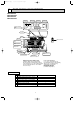
OBH488A-2.qxp 07.9.25 11:35 AM Page 37 OPERATING PROCEDURE PHOTOS 2. Removing the electronic control P.C. board, the power monitor receiver P.C. board, i-see Sensor, SW P.C. board and the terminal block (1) Remove the panel (Refer to 1.) and the corner box. (2) Remove the screw of the V.A. clamp. Remove the V.A. clamp and then the indoor/outdoor connecting wire. (See Photo 2) (3) Remove the sensor holder from the electrical cover.
OBH488A-2.qxp 07.9.25 11:35 AM Page 38 OPERATING PROCEDURE PHOTOS 3. Removing the electrical box (1) Remove the panel (Refer to 1.) and the corner box. (2) Remove the indoor/outdoor connecting wire, the sensor holder, the electrical cover and the earth wire. (Refer to 2.) (3) Disconnect the following connectors on the electronic control P.C. board; fan motor , indoor coil thermistor , vane motor , interlock switch , plasma power P.C. board .
OBH488A-2.qxp 07.9.25 11:36 AM Page 39 OPERATING PROCEDURE PHOTOS 6. Removing the horizontal vane motor (1) Remove the nozzle assembly.(Refer to 4.) (2) Remove the screws of the horizontal vane motor unit, and pull out the horizontal vane motor unit. (4) Remove the screws of the horizontal vane motor unit cover. (5) Remove the horizontal vane motor from the horizontal vane motor unit. (3) Disconnect the connector from the horizontal vane motor.
OBH488A-2.qxp 07.9.25 11:36 AM Page 40 HEAD OFFICE: TOKYO BLDG., 2-7-3, MARUNOUCHI, CHIYODA-KU, TOKYO 100-8310, JAPAN C Copyright 2007 MITSUBISHI ELECTRIC ENGINEERING CO.,LTD Distributed in Oct. 2007. No. OBH488 REVISED EDITION-A 6 Distributed in Aug. 2007. No. OBH488 6 Made in Japan New publication, effective Oct. 2007 Specifications subject to change without notice.