
Engineering Manual

B-107
Unit: mm (inch)
3
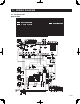
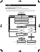
OUTLINES AND DIMENSIONS
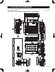
3-1. OUTDOOR UNIT
MXZ-8C48NA MXZ-4C36NAHZ MXZ-5C42NAHZ MXZ-8C48NAHZ
2-12×36 Oval holes
(Foundation Bolt M10<W3/8>)
2-U Shaped notched holes
(Foundation Bolt M10<W3/8>)
Installation Feet
Air Discharge
Rear Air Intake
Side Air Intake
417 <16-13/32>
70
<2-3/4>
225
<8-27/32>
600
<23-5/8>
225
<8-27/32>
330 <13>25 <1>
42
<1-21/32>
60.5
<2-3/8>
28 <1-3/32> 370 <14-9/16> 19 <3/4>
39.5 <1-9/16>
56 <2-7/32>
53 <2-3/32>
0
Drain hole
Bottom piping hole
(Knock-Out)
154
<6-1/16>
136
<5-11/32>
45
<1-25/32>
110
<4-11/32>
160
<6-5/16>
160
<6-5/16>
160
<6-5/16>
81
<3-3/16>
86 <3-3/8>
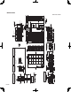
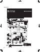
Rear piping cover
Front piping cover
Air intake
Ground for the
branch box
power supply
For the
power supply
For the
branch box
power supply
For the
transmission line
For concentration
control
Terminal connection
From left to right
Handle for moving
Ground for the transmission line
Ground for concentration control
1
2
Handle for moving
Service panel
Ground for the power supply
("GR"marking position)
26 <1-1/32>
1050 <41-11/32>
362 <14-1/4>
1338 <52-11/16>
632 <24-7/8>369 <14-17/32>
485 <19-3/32>
426 <16-25/32>
1067 <42>
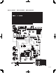
Side Air Intake
Handle for
moving
Rear Air Intake
Handle for
moving
1
2
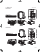
Example of Notes
Rear piping hole
(Knock-Out)
Rear trunking hole
(Knock-Out)
Conduit hole
Conduit hole
60 <2-3/8>
5<3/16>
55 <2-3/16>
55 <2-3/16>27 <1-1/16>
26 <1-1/32> 73 <2-7/8>
92 <3-5/8>
60 <2-3/8>
75 <2-15/16>
<3-5/8>
Conduit hole
Front piping hole
(Knock-Out)
Front trunking hole
(Knock-Out)
Conduit hole
60 <2-3/8>
5
<3/16>
60
<2-3/8>
55 <2-3/16>
26 <1-1/32> 73<2-7/8>
75 <2-15/16>
92 <3-5/8>
27 <1-1/16> 55 <2-3/16>
<3-5/8>
Right trunking hole
(Knock-Out)
Conduit hole
Conduit hole
Right piping hole
(Knock-Out)
73 <2-7/8>
29 <1-5/32>
27 <1-1/16>26 <1-1/32>
92
<3-5/8>
53 <2-3/32>
55 <2-3/16>
60 <2-3/8>
5<3/16>
60 <2-3/8>
92 <3-5/8>
<3-5/8>
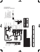
Scale 1:5
1 inch Conduit
attachment
When installing the conduit.
Set the attachment to the
inner side of each panel.
1/2 inch Conduit
attachment
101.5 <4>
24 <15/16>60 <2-3/8>
5<3/16>
24.7 <31/32>
mm<inch>
Piping Knock-Out Hole Details
Min.
Min.
Min.
Min.
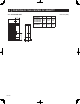
Service space
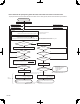
FOUNDATION
<Foundation bolt height>
Max.
Dimensions of space needed
for service access are
shown in the below diagram.
Please secure the unit firmly
with 4 foundation (M10<W3/8>) bolts.
(Bolts and washers must be
purchased locally.)
Piping and wiring connections
can be made from 4 directions:
FRONT, Right, Rear and Below.
1 FREE SPACE (Around the unit)
2 SERVICE SPACE
3 FOUNDATION BOLTS
4 PIPING-WIRING DIRECTIONS
30 <1-3/16>
150
<5-29/32>
500
<19-11/16>
500
<19-11/16>
15 <19/32>
Min. 15mm<19/32>
Min. 15mm<19/32>
FREE
Min. 1000mm<39-3/8> Min. 150mm<5-29/32>
The diagram below shows a basic example.
Explantion of particular details are
given in the installation manuals etc.