
Engineering Manual

A-52
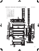
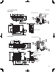
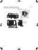
PEAD-A09AA7 PEAD-A12AA7 PEAD-A15AA7 PEAD-A18AA7
Unit: mm(inch)
P-ø2.9(1/8)
6(1/4)
K
L
K
LX(M-1)=N
11(7/16)
112112
(4-7/16) (4-7/16)
Less than 700(27-9/16)
Less than 300
(11-13/16)
(Actual length)
Drain hose(I.D ø32(1-1/4))
(Accessory)
0
-10
0
-7/16
(2-9/16 )
65
Min. 10mm
(7/16)
Min. 300mm
Control box
Access door 2(450×450)
(11-13/16)
(17-3/4X17-3/4)
Ceiling
Ceiling beam
Access door 3
Ceiling
Ceiling beam
Control box
Min. 10mm
(7/16)
Min. 20mm
(13/16)
475(18-3/4)
450
700 Min. 300mm
(11-13/16)
(27-9/16)
(17-3/4)
450
(17-3/4)
100~200
Q
Access door 2
(450×450)
(17-3/4X17-3/4)
450R
50~150 450
(17-3/4)
(17-3/4)
Maintenance
access space
50(2)
700(27-9/16)
Q
50
777(30-5/8)
S
475(18-3/4)
450
Min. 300mm
450
100~200
(3-15/16~7-7/8)
(17-3/4)
(11-13/16)
(2~5-15/16)
(2)
50(2)
700(27-9/16)
Min. 300mm
T
777(30-5/8)
50
Q
(17-3/4)
(11-13/16)
(2)
Access door 4
Bottom of
indoor unit
Access door 1
(450×450)
(17-3/4X17-3/4)
Control box
Maintenance
access space
Maintenance
access space
Control box
Control box
Access door 1
(450×450)
(17-3/4X17-3/4)
Access door 3
(3-15/16~7-7/8)
Y
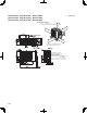
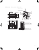
Fig.3
Fig.4
Fig.2
Fig.1
Fig.5
Z
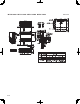
Intake air
Supply air
Intake air
(Viewed from the direction
of the arrow Y)
Bottom of
indoor unit
(Viewed from the direction
of the arrow Y)
(Viewed from the direction
of the arrow Z)
Bottom of
indoor unit
Supply air
Intake
air
Supply
air
Supply
air
Supply
air
Intake
air
Intake
air
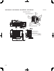
Unit:mm(in.)
Model
P
NK L M
Q
R T
or
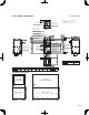
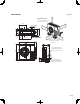
(Access door 2 is not required if enough space is available below the unit for a maintenance worker to work in.)
• Create access door 1 and 2 (450x450mm each) as shown in Fig.2.
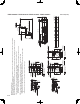
(1) When a space of 300mm or more is available below the unit between the unit and the ceiling. (Fig.1)
and control box in one of the following ways.
Secure enough access space to allow for the maintenance, inspection, and replacement of the motor, fan, drain pump, heat exchanger,
[Maintenance access space]
• Create access door 4 below the control box and the unit as shown in Fig.5.
(At least 20mm of space should be left below the unit as shown in Fig.3.)
• Create access door 1 diagonally below the control box and access door 3 below the unit as shown in Fig.4.
(2) When a space of less than 300mm is available below the unit between the unit and the ceiling.
Select an installation site for the indoor unit so that it's maintenance access space will not be obstructed by beams or other objects.
PEAD-A09,12,15,18AA7
54
260
4
780
10
(2-3/16) (10-1/4) (30-3/4)
900
(35-7/16)
150~250 1500
(59-1/16)(5-15/16)~(9-7/8)
S
1000
(39-3/8)