
Branch Box Installation Manual

12
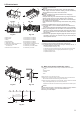
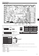
8. Electrical work
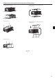
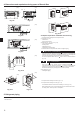
䠆Power supply from Outdoor unit
Power supply
䠆Supply power separately to branch box and outdoor unit
Power supply
L
N
Isolator (Switch)
L
N
Outdoor unit
L
N
B1
B2
L
N
Branch box
S1
S2
S3
S1
S2
S3
"A-control
Indoor unit"
3 pole isolator
(Switch)
2 pole isolator
(Switch)
L
N
Isolator (Switch)
L
N
Branch box
S1
S2
S3
S1
S2
S3
"A-control
Indoorunit"
3 pole isolator
(Switch)
L
N
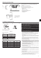
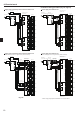
Caution:
After using the isolator, be sure to turn off and on the main power supply to reset the system. Otherwise, the outdoor unit may not be able to detect the
branch box(es) or indoor units.
Warning:
In case of A-control wiring, there is high voltage potential on the S3 terminal caused by electrical circuit design that has no electrical insulation between power
line and communication signal line. Therefore, please turn off the main power supply when servicing. And do not touch the S1, S2, S3 terminals when the power
is energized. If isolator should be used between outdoor unit and branch box/indoor unit and branch box, please use 2-pole or 3-pole type, as shown in the
following fi gures.
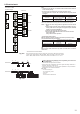
Condition: Branch Box × 2 + SEZ-KD•VA × 5, C=8 (refer to right sample chart)
F2 = 5.1 × 2/8 + 19.8 × 5/8
= 13.65
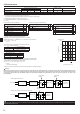
*3 Current sensitivity is calculated using the following formula.
G1 = V2 + V3 × (Wire length[km])
G1 Current sensitivity
30 or less 30 mA 0.1sec or less
100 or less 100 mA 0.1sec or less
Wire thickness (mm
2
)V3
1.5 48
2.5 56
4.0 66
When connecting 3 units of the PLA-ZRP series respectively to the Branch Box
1.5mm
2
using 20m of wiring and connecting the Branch Box and PEFY-VMA to
a single breaker using wiring totaling 100m in length;
G1
= 2.4 × 3 + 3 + 1.6 + 48 × 0.02 × 3 + 56 × 0.1
= 20.28
→ 30 mA Current sensitivity
*5 When the ecodan is connected, the master controller (G-50A etc.) cannot be connected.
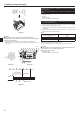
6000
600
60
10
Tripping Time [s]
1
0.1
0.01
12
Rated Tripping current (x)
34 68
C
10 20
SAMPLE
Sample chart
Total operating current of the indoor unit
Minimum wire thickness (mm²)
Capacity (A) Fuse (A)
Breaker for wiring
(NFB)
Ground-fault interrupter *1
Main cable Branch Ground
F0 = 16A or less *2 1.5 1.5 1.5 16 16 20 20A current sensitivity *3
F0 = 25A or less *2 2.5 2.5 2.5 25 25 30 30A current sensitivity *3
F0 = 32A or less *2 4.0 4.0 4.0 32 32 40 40A current sensitivity *3
Apply to IEC61000-3-3 about max. permissive system impedance.
*1 The Ground-fault interrupter should support inverter circuit.
The Ground-fault interrupter should combine using of local switch or wiring breaker.
*2 Please take the larger of F1 or F2 as the value for F0.
F1 = Total operating maximum current of the indoor units × 1.2
F2 = (V1/C)
Connect to Branch box (PAC-MK•BC)
Indoor unit V1 V2
Type 1 SEZ-KD•VA, PCA-RP•KAQ, PLA-ZRP•BA(.UK),
SLZ-KF•VA
19.8
2.4
Type 2 PEAD-RP•JAQ(L).UK 26.9
Type 3 MLZ-KA•VA, SLZ-KA•VAQ(L)3 9.9
Type 4
MSZ-FH•VE, MSZ-SF•VE, MSZ-EF•VE, MSZ-SF•VA,
MSZ-GF•VE
6.8
Type 5 MFZ-KJ•VE, MSXY-FJ 7.4
Type 6 Branch box (PAC-MK•BC) 5.1 3.0
Type 7 ecodan C generation*5 5.1 5.0*
*This value may increase due to a locally connected actuator.
C : Multiple of tripping current at tripping time 0.01s
Please pick up "C" from the tripping characteristic of the breaker.
Connect to Connection kit (PAC-LV11M)
Indoor unit V1 V2
Type 1
MSY-EF•VE, MSY-GE•VA, MSY-GH, MSZ-GE•VA,
MSZ-SF•VA, MSZ-SF•VE, MSZ-EF•VE, MSZ-FH•VE
6.8
2.4
Type 2 MFZ-KJ•VE 7.4
Type 3 Connection kit (PAC-LV11M) 3.5
Indoor unit V1 V2
Type 1
PMFY-VBM, PLFY-VBM, PEFY-VMS1, PCFY-VKM
PKFY-VHM, PKFY-VKM, PFFY-VLRMM, PFFY-VKM,
PLFY-VFM
19.8
2.4
Type 2 PLFY-VCM 9.9
Type 3 PKFY-VBM 3.5
Type 4 PEFY-VMA 38.0 1.6
Type 5
PLFY-VLMD, PEFY-VMH,PEFY-VMR, PDFY-VM
PFFY-VLEM, PFFY-VLRM, PWFY-VM
00