
Branch Box Installation Manual


3
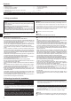
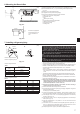
3. Confi rming supplied accessories
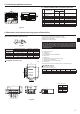
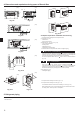
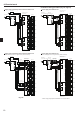
4. Dimensions and required servicing space of Branch Box
PAC-MK51BC (5-branches type)
(mm)
3.1. Check the Branch Box accessories and parts
Accessory name
Q’ty
PAC-
MK31BC
PAC-
MK51BC
1
Washer
(with insulation)
44
2
Washer 4 4
3
Pipe cover (Liquid) 1 1 TO OUTDOOR UNIT
4
Pipe cover (Gas) 1 1 TO OUTDOOR UNIT
5
Pipe cover (Liquid) 3 5 TO INDOOR UNITS
6
Pipe cover (Gas) 3 5 TO INDOOR UNITS
7
Joint cover (Liquid) 1 3
8
Joint cover (Gas) 1 3
9
Band 16 24
Fig. 3-1
29
8
56
4371
B
A
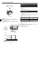
Optional different-diameter (deformed) joints
Fig. 4-1
* Please connect 2 indoor units or more with 1 system.
* Up to 2 branch boxes may be connected to 1 outdoor unit.
* Suspension bolt : W3/8 (M10)
* Refrigerant pipe fl ared connection
* The piping connection size differs according to the type and capacity of
indoor units. Match the piping connection size for indoor unit and branch
box. If the piping connection size of branch box does not match the pip-
ing connection size of indoor unit, use optional different-diameter (de-
formed) joints to the branch box side. (Connect deformed joint directly to
the branch box side.)
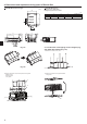
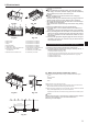
A
Suspension bolt pitch
B
To indoor unit
C
To outdoor unit
D
Service panel (for LEV, THERMISTOR)
E
Electric cover
F
Rubber bush
G
Terminal block (to indoor unit on control board)
H
Terminal block (to outdoor unit)
J
Terminal block (for communication cable)
K
Cable clamp
* Ensure that the branch box is installed as shown on the below drawing.
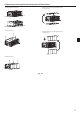
PAC-MK51BC (Fig.4-2)
Suspension bolt: W3/8 (M10)
Refrigerant pipe fl ared connection
ABCDE
To outdoor unit
Liquid pipe
ø6.35 ø6.35 ø6.35 ø6.35 ø6.35 ø9.52
Gas pipe
ø9.52 ø9.52 ø9.52 ø9.52 ø12.7 ø15.88
Model name
Connected pipes diameter Diameter A Diameter B
mm mm mm
MAC-A454JP ø9.52 → ø12.7 ø9.52 ø12.7
MAC-A455JP ø12.7 → ø9.52 ø12.7 ø9.52
MAC-A456JP ø12.7 → ø15.88 ø12.7 ø15.88
PAC-493PI ø6.35 → ø9.52 ø6.35 ø9.52
PAC-SG76RJ-E ø9.52 → ø15.88 ø9.52 ø15.88
mm
81
96450
70707070
25
25
25
25
25
170
4765
93
24
12
320
402
40278
7087
102
90
DK
FE
H
G
J
EDCBA
EDCBA
C
A
B
A
Fig. 4-2
Conversion formula
1/4 F ø6.35
3/8 F ø9.52
1/2 F ø12.7
5/8 F ø15.88
3/4 F ø19.05