
M-Series SEZ-KA Engineering Manual


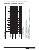


Table Of Contents
- Contents
- 1. INDOOR UNITS
- 2. OUTDOOR UNITS
- 3. SYSTEM
- 3-1. SPECIFICATIONS
- 3-2. EXTERNAL DIMENSIONS
- 3-3. CENTER OF GRAVITY
- 3-4. ELECTRICAL WIRING DIAGRAMS
- 3-5. REFRIGERANT SYSTEM DIAGRAMS
- 3-6. CAPACITY CORRECTION CURVE BY TEMPERATURE
- 3-7. CAPACITY CORRECTION TABLE BY TEMPERATURE
- 3-8. Capacity correction curve by refrigerant piping length
- 3-9. CAPACITY CORRECTION TABLE BY REFRIGERANT PIPING LENGTH
- 3-10. CHARGE CALCULATIONS
- 3-11. AIR FLOW DATA
- 3-12. SOUND PRESSURE LEVELS
- 3-13. STANDARD OPERATION RANGE
- 3-14. ACCESSORIES

SEZ-22
SEZ Ducted Heat Pump Systems (August 2014)
Due to continuing improvement, above specication may be subject to change without notice.
© 2014 Mitsubishi Electric US, Inc.
3-6. CAPACITY CORRECTION CURVE BY TEMPERATURE
For The Combination Of Outdoor Unit SUZ-KA·NA
(1) Cooling Performance Curve
71
67
63
71
67
63
1.4
1.3
1.2
1.1
0.8
1.0
0.9
Indoor intake air WB temperature (°F)
65 75 85 95 105 115
Outdoor intake air DB temperature (°F)
1.2
1.1
1.0
0.9
0.8
0.7
Indoor intake air WB temperature (°F)