
MXZ-SM42NAMHZ Installation Manual


14
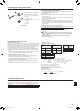
Example of a group operation system with multiple outdoor units (Shielding wires and address setting are necessary.)
<Examples of Transmission Cable Wiring: When Not Using a Branch Box>
■ M-NET Remote Controller (Fig. 6-2)
■ MA Remote Controller (Fig. 6-3)
<Wiring Method and Address Settings: without Branch box system>
a. Always use shielded wire when making connections between the outdoor unit (OC) and the indoor unit (M-IC).
b. Use feed wiring to connect terminals M1 and M2 and the ground terminal on the transmission cable terminal block (TB3) of each outdoor unit (OC) to terminals M1, M2
and terminal S on the transmission cable terminal block of the indoor unit (M-IC).
c. Connect terminals 1 (M1) and 2 (M2) on the transmission cable terminal block of the indoor unit (M-IC) that has the most recent address within the same group to the
terminal block on the remote controller (M-NET RC).
d. Connect together terminals M1, M2 and terminal S on the terminal block for centralized control (TB7) for the outdoor unit (OC).
e. The jumper connector CN41 on the control panel does not change.
f. Connect shield ground of the indoor units transmission line to the shield (S) terminal of (TB3).
Connect shield ground of the line between outdoor units and the centralized control system transmission line to the shield (S) terminal of (TB7).
g. Set the address setting switch as follows.
Unit Range Setting Method
M-IC (Main) 01 to 50 Use the most recent address within the same group of indoor units
M-IC (Sub) 01 to 50
Use an address, other than that of the M-IC (Main) from among the units within the same group of indoor units. This
must be in sequence with the M-IC (Main)
OC 51 to 100
Use the most recent address of all the indoor units plus 50
* The address automatically becomes “100” if it is set as “01 - 50”.
M-NET RC (Main) 101 to 150 Set at an M-IC (Main) address within the same group plus 100
M-NET RC (Sub) 151 to 200 Set at an M-IC (Main) address within the same group plus 150
MA-RC – Unnecessary address setting (Necessary main/sub setting)
h. The group setting operations among the multiple indoor units is done by the remote controller (M-NET RC) after the electrical power has been turned on.
<Wiring Method and Address Setting: include Branch box system>
Please refer to the Branch box Installation Manual.
6. Electrical work
<Example of Transmission Cable Wiring: Not using Branch box>
■
M-NET Remote Controller
■
MA Remote Controller
Fig. 6-3Fig. 6-2
A
: Group 1
B
: Group 2
C
: Group 3
D
: Shielded Wire
E
: Sub Remote
Controller
( ): Address
<Permissible Lengths>
• Maximum line length via outdoor units: L
1
+L
2
+L
3
+L
4
,
L
3
+L
4
+L
5
+L
6
and L
1
+L
2
+L
5
+L
6
{ 500 m [1640 ft]
(1.25 mm² [AWG16] or more)
• Indoor/outdoor transmission line Maximum length: L
1
,
L
3
+L
4
, L
2
+L
5
and L
6
{ 200 m [656 ft] (1.25 mm² [AWG16]
or more)
• Remote controller cable length:
R
1
, R
2
+R
3
{ 10 m [33 ft] (0.5 to 1.25 mm² [AWG20 to
AWG16])
If the length exceeds 10 m [33 ft], use a 1.25 mm²
[AWG16] shielded wire. The section of the cable that
exceeds 10 m [33 ft] must be included in the max
length via outdoor units and max transmission cable
length.
<Permissible Lengths>
• Maximum line length via outdoor units (M-NET cable): L
1
+L
2
+L
3
+L
4
,
L
3
+L
4
+L
5
+L
6
and L
1
+L
2
+L
5
+L
6
{ 500 m [1640 ft] (1.25 mm² [AWG16] or more)
• Indoor/outdoor transmission line Maximum length (M-NET cable): L
1
, L
3
+L
4
,
L
2
+L
5
and L
6
{ 200 m [656 ft] (1.25 mm² [AWG16] or more)
• Remote controller cable length: m
1
, m
1
+m
2
+m
3
and m
1
+m
2
+m
3
+m
4
{ 200 m
[656 ft] (0.3 to 1.25 mm² [AWG22 to AWG16])
A
B
C
E
M-IC
S 2M 1M
TB5
M-NET RC
(01)
M-IC
S 2M 1M
TB5
(03)
M-IC
S 2M 1M
TB5
(02)
M-IC
M1 M2 S
TB5
(04)
M-IC
S 2M 1M
TB5
(05)
S 2M 1M
TB5
(07)
M-IC
S 2M 1M
TB5
(06)
L1
(101)
M-NET RC
(105)
(104)
M-NET RC
(155)
L3 L4
AB AB AB
AB
A
B
C
E
M-IC
S 21 2M 1M
TB5 TB15
12
TB15
12
TB15
12
TB15
12
TB15
12
TB15
12
TB15
MA-RC
(01)
M-IC
S 2M 1M
TB5
(03)
M-IC
M1 M2 S
TB5
(02)
M-IC
M1 M2 S
TB5
(04)
M-IC
M1 M2 S
TB5
(05)
M-IC
M1 M2 S
TB5
(07)
M-IC
M1 M2 S
TB5
(06)
L1
m 3
L3 L4
m
3
AB
AB
AB
m
1
m 1
m 2 m 2
AB
M-NET RC
MA-RC
MA-RC
MA-RC
M-IC
R2
R
3
R1
m
4
m1
S
S
L6
M1M2
M1M2
M1M2S
M1M2S
L
6
D
M1M2S
TB7
M1M2S
TB3
(51)
OC
L2
L5
M1M2SM1M2S
TB3
(53)
OC
TB7
D
M1M2S
TB7
M1M2S
TB3
(51)
OC
L2
L5
M1M2SM1M2S
TB3
(53)
OC
TB7
Power
Supply Unit
System
controller
Power
Supply Unit
System
controller
en
RG79F368H03_01en.indd 14 2021/10/05 17:04:25
015