
MXZ-SM42NAMHZ Installation Manual


13
6. Electrical work
6.1. Caution
1 Follow ordinance of your governmental organization for technical standard
related to electrical equipment, wiring regulations and guidance of each electric
power company.
2 Use self-extinguishing distribution cables for power supply wiring.
3 Wiring for control (hereinafter referred to as transmission line) shall be (5 cm
[2inch]ormore)apartfrompowersourcewiringsothatitisnotinuencedby
electric noise from power source wiring. (Do not insert transmission line and
power source wire in the same conduit.)
4 Be sure to provide designated grounding work to outdoor unit.
5 Give some allowance to wiring for electrical part box of indoor and outdoor
units, because the box is sometimes removed at the time of service work.
6 Never connect the main power source to terminal block of transmission line. If
connected, electrical parts will be burnt out.
7 Use 2-core shield cable for transmission line. If transmission lines of different
systems are wired with the same multiplecore cable, the resultant poor trans-
mitting and receiving will cause erroneous operations.
8 Onlythetransmissionlinespeciedshouldbeconnectedtotheterminalblock
for outdoor unit transmission.
(Transmission line to be connected with indoor unit : Terminal block TB3 for
transmission line, Other : Terminal block TB7 for centralized control)
Erroneous connection does not allow the system to operate.
9 In case to connect with the upper class controller or to conduct group operation
in different refrigerant systems, the control line for transmission is required
between the outdoor units each other.
Connect this control line between the terminal blocks for centralized control.
(2-wire line with no polarity)
When conducting group operation in different refrigerant systems without con-
necting to the upper class controller, replace the insertion of the short circuit
connector from CN41 of one outdoor unit to CN40.
0 Before turning outdoor unit on, be sure to turn the indoor units and the branch
boxes on.
6.3. Wiring transmission cables
1 Types of control cables
1. Wiring transmission cables
Types of transmission cable Shielding wire (2-core) CVVS, CPEVS or MVVS
Cable diameter More than 1.25 mm
2
[AWG 16]
Maximum wiring length Within 200 m
[656 ft]
2. M-NET Remote control cables
Types of remote control cable Shielding wire (2-core) CVVS, CPEVS or MVVS
Cable diameter 0.5 to 1.25 mm
2
[AWG 20 to AWG 16]
Remarks
When the wiring length exceeds 10 m [32 ft], use
cablewiththesamespecicationsastransmis-
sion line wiring.
3. MA Remote control cables
Type of remote control cable Sheathed 2-core cable (unshielded) CVV
Cable diameter
0.3 to 1.25 mm
2
[AWG 22 to AWG 16] (0.75 to
1.25 mm
2
[AWG 18 to AWG 16])*
Remarks Within 200 m [656 ft]
* Connected with simple remote controller.
2 Wiring examples
• Controller name, symbol and allowable number of controllers.
Name Symbol Allowable number of controllers
Outdoor unit controller OC –
Indoor unit
controller
CITY
MULTI
series
M-IC
MXZ-SM36 1 to 11 units per 1 OC
MXZ-SM42
1 to 12 units per 1 OCMXZ-SM48
MXZ-SM60
M, S, P
series
A-IC
MXZ-SM36 2 to 4 units per 1 OC *1
MXZ-SM42 2 to 5 units per 1 OC *1
MXZ-SM48
2 to 8 units per 1 OC *1
MXZ-SM60
Branch box BC 0 to 2 units per 1 OC *1
Remote
controller
M-NET M-NET RC *2
Maximum of 12 controllers for 1 OC (Can
not be connected if Branch box is used.) *1
MA MA-RC Maximum of 2 per group
Wireless WL-RC –
Note:
*1. The number of connectable units may be limited by some conditions such
as an indoor unit’s capacity or each unit’s equivalent power consumption.
*2. Don’t use the Lossnay controller (PZ-61DR-E, PZ-43SMF-E, PZ-52SF-E, PZ-
60DR-E).
L1
L2
GR
M1
S
M2 M1
S
M2
TB3TB1 TB7
B1 B2
TB1B
D
A
F
B
C
E
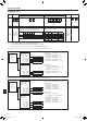
A : Power source
B : Power supply for branch box
C : Screw on the electrical component box
6.2. Control box and connecting position of wiring
(Fig. 6-1)
1. Connect the wiring between the outdoor unit and the indoor unit or branch box
to the transmission terminal block (TB3) of the outdoor unit.
Connect the wiring between the outdoor unit and the centralized control system
to the transmission terminal block (TB7) of the outdoor unit.
When using shielded wiring, connect the ground of the shielded wiring to the
shield terminal (S) of the terminal block (TB3) or (TB7).
If the connection of the outdoor unit’s transmission power supply connector has
been changed from CN41 to CN42, connect the shield terminal (S) of the termi-
nal block (TB7) to the screw F using the included lead wire.
* The shield (S) terminal of the transmission terminal block (TB3) is connected to
the ground E when the unit is shipped from the factory.
2. Conduit mounting plates are being provided. Remove the knock-out pieces
from the piping cover, pass the power supply and transmission wires through
the appropriate knock-out holes, and connect the wires to the terminal block.
3. The terminal block (TB1B) is for supplying power to the branch box
(208
/ 230 V, max. 6A).
4. Fix power source wiring to the terminal block by using buffer bushing for tensile
force (PG connection or the like).
Caution:
Never connect the transmission line for the branch box or the central control
system transmission line to this terminal block (TB1B). If the transmission
lines are connected, the indoor unit, branch box or system controller could
be damaged.
Fig. 6-1
D : Transmission line
E : Screw on the electrical component box for
ground connection (TB3)
F : Screw on the electrical component box for
ground connection (TB7)
CONDUIT PLATE:
accessory
ø24 knock-out hole
(For transmission wires)
ø37 knock-out hole
(For power supply wires)
en
RG79F368H03_01en.indd 13 2021/10/05 17:04:25
014