HFC utilized R410A SPLIT-TYPE, HEAT PUMP AIR CONDITIONERS November 2021 No. OCH789 TECHNICAL & SERVICE MANUAL [Model Name] MXZ-SM36NAM MXZ-SM48NAM MXZ-SM60NAM MXZ-SM36NAMHZ MXZ-SM42NAMHZ MXZ-SM48NAMHZ [Service Ref.] MXZ-SM36NAM-U1 MXZ-SM48NAM-U1 MXZ-SM60NAM-U1 MXZ-SM36NAMHZ-U1 MXZ-SM42NAMHZ-U1 MXZ-SM48NAMHZ-U1 Note: • This service manual describes technical data of the outdoor units only. CONTENTS Model name indication OUTDOOR UNIT 1. SAFETY PRECAUTION························ 2 2.
1 SAFETY PRECAUTION 1-1. ALWAYS OBSERVE FOR SAFETY Before obtaining access to terminal, all supply circuit must be disconnected. Preparation before the repair service Precautions during the repair service • Prepare the proper tools. • Prepare the proper protectors. • Provide adequate ventilation. • After stopping the operation of the air conditioner, turn off the power-supply breaker. • Discharge the condenser before the work involving the electric parts.
The refrigerant oil applied to flare and flange connections must be ester oil, ether oil or alkylbenzene oil in a small amount. Use the specified refrigerant only. Never use any refrigerant other than that specified. Doing so may cause a burst, an explosion, or fire when the unit is being used, serviced, or disposed of. Correct refrigerant is specified in the manuals and on the spec labels provided with our products.
Cautions for refrigerant piping work New refrigerant R410A is adopted for replacement inverter series. Although the refrigerant piping work for R410A is same as for R22, exclusive tools are necessary so as not to mix with different kind of refrigerant. Furthermore as the working pressure of R410A is 1.6 times higher than that of R22, their sizes of flared sections and flare nuts are different.
2 OVERVIEW OF UNITS 2-1. Auxiliary HEATING ON/OFF CONTROL SET-UP (1) Auxiliary heating operation controls another heat source that depends on the main system's operations, which means the interlock operation shown in "b)" will be possible. a) Indoor unit must be R410A UL model for this function to operate. b) Different Indoor unit applications that can be applied: (2) Outdoor unit DIPSW5-4 for auxiliary heating control: Set DIPSW5-4 when power is turned off at unit.
(4) Determine fan speed setting during indoor thermo-OFF conditions: a) These settings are done within Indoor DIPSW1-7 and DIPSW1-8, see chart below for options. b) Recommended SW1-7 OFF and SW1-8 ON will determine airflow based on "Setting on the remote controller".
(6) Locally procured wiring A basic connection method is shown. (i.e.
2-2. SYSTEM CONSTRUCTION 4HP 4.
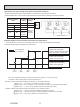
Outdoor unit Rated capacity (kBtu/h) Cooling Heating Refrigerant Connectable Capacity class indoor unit MXZ-SM36NAM-U1 MXZ-SM36NAMHZ-U1 4HP 36 42 MXZ-SM48NAM-U1 MXZ-SM48NAMHZ-U1 5HP 48 54 R410A MXZ-SM42NAMHZ-U1 MXZ-SM60NAM-U1 4.5HP 42 48 7HP 60 66 Type 06 to Type 36 Caution: The indoor unit which rated capacity exceeds 36 kBtu/ h (Type 36) can NOT be connected.
2-3. SYSTEM SPECIFICATIONS (1) Outdoor Unit MXZ-SM48NAM-U1 MXZ-SM36NAM-U1 MXZ-SM60NAM-U1 MXZ-SM42NAMHZ-U1 MXZ-SM48NAMHZ-U1 MXZ-SM36NAMHZ-U1 Capacity Cooling (kBtu/h) 36 42 48 60 Heating (kBtu/h) 42 48 54 66 Compressor (kW) 2.8 2.9 3.4 3.9 Service Ref. Cooling/Heating capacity indicates the maximum value at operation under the following condition. Cooling Indoor D.B. 80°F/W.B. 67°F: [D.B. 26.7°C/W.B. 19.4°C] Outdoor D.B. 95°F/W.B. 75°F: [D.B. 35°C/W.B. 23.9°C] Heating Indoor D.B. 70°F/W.B. 60°F: [D.B. 21.
SPECIFICATIONS 3 Service Ref. Indoor type Capacity Rated*1 Rated power consumption*1 Current input (208/230V) EER SEER Capacity Rated 47°F*1 Capacity Max. 17°F*2 Heating Cooling Btu/h W A Btu/h/W Btu/h Btu/h Btu/h W A W/W - Capacity Max. 5°F Rated power consumption 47°F*1 Current input (208/230V) COP 47°F*1 HSPF 4/5 Power supply Breaker Size/Max. fuse size Min.
Heating Cooling Service Ref. Indoor type Capacity Rated*1 Rated power consumption*1 Current input (208/230V) EER SEER Capacity Rated 47°F*1 Capacity Max. 17°F*2 Capacity Max. 5°F Rated power consumption 47°F*1 Current input (208/230V) COP 47°F*1 HSPF 4/5 Power supply Breaker Size/Max. fuse size Min.
Service Ref. Indoor type Capacity Rated*1 Rated power consumption*1 Current input (208/230V) EER SEER Capacity Rated 47°F*1 Capacity Max. 17°F*2 Capacity Max. 5°F Rated power consumption 47°F*1 Current input (208/230V) COP 47°F*1 HSPF 4/5 Power supply Breaker Size/Max. fuse size MXZ-SM60NAM-U1 Heating Cooling Btu/h W A Btu/h/W Btu/h Btu/h Btu/h W A W/W - Non-Ducted 60,000 4,510 21.9/19.8 13.30 20.0 66,000 65,000 57,000 4,720 22.9/20.7 4.10 12.0/8.8 Mix Ducted 60,000 60,000 4,920 5,405 23.9/21.6 26.
4 DATA 4-1. SELECTION OF COOLING/HEATING UNITS How to determine the capacity when less than or equal 100% indoor model size units are connected in total: The purpose of this flow chart is to select the indoor and outdoor units. For other purposes, this flow chart is intended only for reference.
How to determine the capacity when greater than 100% indoor model size units are connected in total: The purpose of this flow chart is to select the indoor and outdoor units. For other purposes, this flow chart is intended only for reference.
Design Condition 98.6ºF (37.0ºC) 30.3 kBtu/h Outdoor Design Dry Bulb Temperature Total Cooling Load Room1 Indoor Design Dry Bulb Temperature Indoor Design Wet Bulb Temperature Cooling Load Room2 Indoor Design Dry Bulb Temperature Indoor Design Wet Bulb Temperature Cooling Load Indoor/Outdoor Equivalent Piping Length 80.6ºF (27.0ºC) 68.0ºF (20.0ºC) 13.6 kBtu/h 75.2ºF (24.0ºC) 66.2ºF (19.0ºC) 16.
(7) Comparison with Essential Load Against the essential load 30.3 kBtu/h, the maximum system capacity is 32.4 kBtu/h: Proper outdoor units have been selected. (8) Calculation of Maximum Indoor Unit Capacity of Each Room CTx = CTi, thus, calculate by the calculation below Room1 Indoor Unit Rating × Indoor Design Temperature Correction = 15.0 × 1.02 = 15.3 kBtu/h OK: fulfills the load 13.6 kBtu/h Room2 Indoor Unit Rating × Indoor Design Temperature Correction = 18.0 × 0.95 = 17.
Total capacity of indoor unit Total Outdoor Unit Capacity (CTo) CTo = Outdoor Unit Rating × G(CTi)*1× Outdoor Design Temperature Correction × Piping Length Correction × Defrost Correction = 42.0 × 1.0 × 0.94 × 0.89 = 35.1 kBtu/h *1 G(CTi) is used only when greater than 100% indoor model size are connected in total, refer to STANDARD CAPACITY DIAGRAM. Table 1 Table of correction factor at frost and defrost Outdoor Intake temperature Correction factor 43(6) 1.0 37(4) 0.98 36(2) 0.
(1) Rated power input of outdoor unit 3.02 kW (2) Calculation of the average indoor temperature power input coefficient Coefficient of the outdoor unit for indoor unit 1 (Outdoor temp. 26.6°F [−3°C] W.B., Indoor temp. 70°F [21.1°C] D.B.) 1.16 (Refer to “4-2. CORRECTION BY TEMPERATURE”.) Coefficient of the outdoor unit for indoor unit 2 (Outdoor temp. 26.6°F [−3°C] W.B., Indoor temp. 78.8°F [26°C] D.B.) 1.09 (Refer to “4-2. CORRECTION BY TEMPERATURE”.) n n k=1 k=1 Average indoor temp.
4-2. CORRECTION BY TEMPERATURE CITY MULTI could have varied capacity at different designing temperature. Using the nominal cooling/heating capacity value and the ratio below, the capacity can be observed at various temperature. Figure 7 Indoor unit temperature correction To be used to correct indoor unit capacity only Ratio of cooling capacity 1.2 1.0 0.8 0.6 0.4 59 15 60.8 16 62.6 17 64.4 66.2 68 69.8 18 19 20 21 Indoor Temperature 71.6 22 73.4 23 75.2 [°FW.B.] 24 [°CW.B.
MXZ-SM36NAM-U1 MXZ-SM48NAM-U1 MXZ-SM60NAM-U1 Figure 9 Indoor unit temperature correction To be used to correct indoor unit capacity only 1.3 Ratio of heating capacity 1.2 1.1 1.0 0.9 0.8 0.7 0.6 59 15 60.8 62.6 64.4 66.2 68 69.8 71.6 73.4 75.2 16 17 18 19 20 21 22 23 24 Indoor Temperature 77 25 78.8 80.6 [°F D.B.] 26 27 [°C D.B.] Figure 10 Outdoor unit temperature correction To be used to correct outdoor unit capacity only Indoor Temperature 1.4 Ratio of heating capacity 1.3 1.2 1.
MXZ-SM36NAMHZ-U1 MXZ-SM42NAMHZ-U1 MXZ-SM48NAMHZ-U1 Figure 11 Indoor unit temperature correction To be used to correct indoor unit capacity only 1.3 Ratio of heating capacity 1.2 1.1 1.0 0.9 0.8 0.7 0.6 59 15 60.8 62.6 64.4 66.2 16 17 18 19 68 20 69.8 71.6 73.4 75.2 21 22 23 24 77 25 78.8 80.6 [°F D.B.] 26 27 [°C D.B.] Indoor Temperature Figure 12 Outdoor unit temperature correction To be used to correct outdoor unit capacity only Indoor Temperature 1.4 Ratio of heating capacity 1.
4-3. STANDARD OPERATION DATA (REFERENCE DATA) Operation MXZ-SM36NAM-U1 Operating Ambient Indoor conditions temperature Outdoor Indoor unit No. of connected units Piping No. of units in operation Model Main pipe Branch pipe Total pipe length Fan speed Amount of refrigerant Outdoor unit LEV opening Pressure Temp.
4-4. STANDARD CAPACITY DIAGRAM Before calculating the sum of total capacity of indoor units, please convert the value into the kW model capacity following the formula on "4-1-1. Method for obtaining system cooling and heating capacity". 4-4-1. MXZ-SM36NAM-U1 MXZ-SM36NAMHZ-U1 G(x) Ratio of capacity 1.0 0.8 0.6 0.4 0.2 0.0 0 10 20 30 40 50 40 50 Total capacity of indoor units (kBtu/h) Ratio of power input 1.6 1.4 1.2 1.0 0.8 0.6 0.4 0.2 0.
4-4-2. MXZ-SM36NAM-U1 MXZ-SM36NAMHZ-U1 G(x) Ratio of capacity 1.0 0.8 0.6 0.4 0.2 0.0 0 10 20 30 40 50 40 50 Total capacity of indoor units (kBtu/h) Ratio of power input 1.6 1.4 1.2 1.0 0.8 0.6 0.4 0.2 0.0 0 10 20 30 Total capacity of indoor units (kBtu/h) 1.6 Ratio of current 1.4 1.2 208, 230 V 1.0 0.8 0.6 0.4 0.2 0.
4-4-3. MXZ-SM42NAMHZ-U1 Nominal cooling capacity Input Current (208V) Current (230V) Non-Ducted Mix Ducted 42,000 3,130 15.5 14.0 42,000 3,470 17.1 15.4 42,000 3,890 19.0 17.2 Btu/h W A A G(x) Ratio of capacity 1.2 1.0 0.8 0.6 0.4 0.2 0.0 0 10 20 30 40 50 60 50 60 Total capacity of indoor units (kBtu/h) Ratio of power input 1.6 1.4 1.2 1.0 0.8 0.6 0.4 0.2 0.0 0 10 20 30 40 Total capacity of indoor units (kBtu/h) 1.6 Ratio of current 1.4 1.2 208, 230 V 1.0 0.8 0.
4-4-4. MXZ-SM42NAMHZ-U1 Non-Ducted Mix Ducted 48,000 3,430 16.8 15.2 48,000 3,750 18.3 16.6 48,000 4,140 20.2 18.3 Nominal heating capacity Btu/h Input W Current (208V) A Current (230V) A G(x) Ratio of capacity 1.2 1.0 0.8 0.6 0.4 0.2 0.0 0 10 30 20 40 60 50 Total capacity of indoor units (kBtu/h) Ratio of power input 1.6 1.4 1.2 1.0 0.8 0.6 0.4 0.2 0.0 0.0 7.5 15.0 22.5 30.0 37.5 45.0 52.5 60.0 Total capacity of indoor units (kBtu/h) Ratio of current 1.6 1.4 1.
4-4-5. MXZ-SM48NAM-U1 MXZ-SM48NAMHZ-U1 G(x) 1.2 Ratio of capacity 1.0 0.8 0.6 0.4 0.2 0.0 0 10 20 30 40 50 60 70 60 70 Total capacity of indoor units (kBtu/h) Ratio of power input 1.6 1.4 1.2 1.0 0.8 0.6 0.4 0.2 0.0 0 10 20 30 40 50 Total capacity of indoor units (kBtu/h) 1.6 Ratio of current 1.4 208, 230 V 1.2 1.0 0.8 0.6 0.4 0.2 0.
4-4-6. MXZ-SM48NAM-U1 MXZ-SM48NAMHZ-U1 G(x) 1.2 Ratio of capacity 1.0 0.8 0.6 0.4 0.2 0.0 0 10 20 30 40 50 60 70 60 70 Total capacity of indoor units (kBtu/h) Ratio of power input 1.6 1.4 1.2 1.0 0.8 0.6 0.4 0.2 0.0 0 10 20 30 40 50 Total capacity of indoor units (kBtu/h) 1.6 Ratio of current 1.4 208, 230 V 1.2 1.0 0.8 0.6 0.4 0.2 0.
4-4-7. MXZ-SM60NAM-U1 G(x) 1.2 Ratio of capacity 1.0 0.8 0.6 0.4 0.2 0.0 0 10 20 30 40 50 60 70 80 70 80 Total capacity of indoor units (kBtu/h) Ratio of power input 1.2 1.0 0.8 0.6 0.4 0.2 0.0 0 10 20 30 40 50 60 Total capacity of indoor units (kBtu/h) 1.2 Ratio of current 1.0 208, 230 V 0.8 0.6 0.4 0.2 0.
4-4-8. MXZ-SM60NAM-U1 G(x) Ratio of capacity 1.2 1.0 0.8 0.6 0.4 0.2 0.0 0 10 20 30 40 50 60 70 80 70 80 Total capacity of indoor units (kBtu/h) Ratio of power input 1.2 1.0 0.8 0.6 0.4 0.2 0.0 0 10 20 30 40 50 60 Total capacity of indoor units (kBtu/h) 1.2 Ratio of current 1.0 208, 230 V 0.8 0.6 0.4 0.2 0.
4-5. CORRECTING CAPACITY FOR CHANGES IN THE LENGTH OF REFRIGERANT PIPING (1) During cooling, obtain the ratio (and the equivalent piping length) of the outdoor units rated capacity and the total in-use indoor capacity, and find the capacity ratio corresponding to the standard piping length from Figure 13 to 17. Then multiply by the cooling capacity from Figure 7 and 8 in "4-2. CORRECTION BY TEMPERATURE" to obtain the actual capacity.
Figure 15 M XZ-SM48NAM-U1 MXZ-SM48NAMHZ-U1 Total capacity of indoor unit 1.00 0.95 24 [kBtu/h] 0.90 Capacity ratio 0.85 0.80 36 [kBtu/h] 0.75 0.70 48 [kBtu/h] 0.65 62.4 [kBtu/h] 0.60 0.55 0.50 0 50 100 150 200 Figure 16 MXZ-SM60NAM-U1 250 300 350 400 Piping equivalent length (ft) 450 500 550 600 Total capacity of indoor unit 1.00 Capacity ratio 0.95 30 [kBtu/h] 45 [kBtu/h] 0.90 60 [kBtu/h] 0.85 0.80 78 [kBtu/h] 0.75 0.
Figure 17 M XZ-SM36NAM-U1 MXZ-SM42NAMHZ-U1 MXZ-SM48NAM-U1 MXZ-SM36NAMHZ-U1 MXZ-SM48NAMHZ-U1 Total capacity of indoor unit 1.00 0.95 Capacity ratio 0.90 0.85 0.80 0.75 0.70 0 50 100 150 200 Figure 18 MXZ-SM60NAM-U1 250 300 350 400 Piping equivalent length (ft) 450 500 550 600 Total capacity of indoor unit 1.00 Capacity ratio 0.95 0.90 0.85 0.80 0.75 0.
4-6.
FREE Front trunking hole (Knock-Out) 60<2-3/8> Conduit hole ( 37<1-15/32>Knock-Out) Front piping hole (Knock-Out) > 92<3-5/8> 75<2-15/16> 92 <3-5/8 > 92 55<2-3/16> 29<1-5/32> 92<3-5/8> <3-5/8 Right piping hole (Knock-Out) Conduit hole ( 24<15/16>Knock-Out) Min. 500 <19-11/16> 53<2-3/32> Handle for moving Service space 9.52 (3/8F) 55<2-3/16> Piping Knock-Out Hole Details *1 • • • Indication of STOP VALVE connection location. 2 • • • Refrigerant LIQUID pipe connection (FLARE) A Min.
6 WIRING DIAGRAM MXZ-SM36NAM-U1 MXZ-SM48NAM-U1 OCH789 37
MXZ-SM60NAM-U1 OCH789 38
MXZ-SM36NAMHZ-U1 OCH789 MXZ-SM42NAMHZ-U1 39 MXZ-SM48NAMHZ-U1
901 901 Address SW 061 Outdoor unit 901 901 901 1 161 901 901 Address SW M-NET remote controller 901 Address SW D 2 WL-RC 901 Address SW CITY MULTI Indoor unit 012 901 3 4 A Control Indoor unit D (004) 1 Note: The refrigerant system which includes branch box cannot be operated as a group.
7-2. Special Function Operation and Settings for M-NET Remote Controller For the detailed procedure of "group settings" and "paired settings", refer to the remote controller's manuals. 7-3.
MXZ-SM36NAMHZ-U1 MXZ-SM42NAMHZ-U1 MXZ-SM48NAMHZ-U1 Refrigerant flow in cooling Refrigerant flow in heating Thermistor (TH7) Check valve Service port 4-way valve Strainer Refrigerant Gas pipe Ball valve Solenoid valve (SV1) Check valve Strainer Thermistor (TH6) Strainer Low pressure sensor(63LS) Oil separator High pressure sensor (63HS) Capillary tube High pressure switch (63H) Thermistor (TH4) Distributor Thermistor (TH3)
MXZ-SM36NAM-U1 MXZ-SM48NAM-U1 Thermistor(TH-A to E) Check valve Service port Strainer Room temperature thermistor (TH1 or RT11) Solenoid valve(SV1) Ball valve Check valve Strainer Thermistor(TH6) Oil separator High pressure switch(63H) Capillary tube1 Strainer Thermistor(TH4) Restrictor valve LEV-A to E (Linear expansion) Pipe temperature thermistor (TH2 or RT13) Thermistor(TH2) Stop valve S
MXZ-SM60NAM-U1 Thermistor(TH-A to E) Check valve Service port Strainer Room temperature thermistor (TH1 or RT11) Ball valve Solenoid valve(SV1) Check valve Strainer Strainer Thermistor(TH6) Strainer Low pressure sensor(63LS) Condenser / evaporator temperature thermistor LEV-A to E (Linear expansion) Pipe temperature thermistor (TH2 or RT13) Indoor Capillary tube1 Capillary tube2 Strainer Strainer High pressure swit
7-4. SYSTEM CONTROL 7-4-1. Example for the System • Example for wiring control cables, wiring method and address setting, permissible lengths, and the constraint items are listed in the standard system with detailed explanation. A. Example of an M-NET remote controller system (address setting is necessary.) Example of wiring control cables 1.
• Name, Symbol and the Maximum Remote controller Units for Connection Name Outdoor unit CITY MULTI series indoor unit M-NET remote controller Symbol OC M-IC M-NET RC Maximum units for connection — Refer to "3. SPECIFICATIONS". Maximum 2 M-NET RC for 1 indoor unit, Maximum 12 M-NET RC for 1 OC Permissible Lengths Indoor/outdoor transmission line Maximum length AWG 16 [1.25 mm²] L1 + L2 [ 656 ft [200 m] M-NET Remote controller cable length 1. If AWG 20 to AWG 16 [0.5 to 1.25 mm²] R1, R2 [ 33ft [10 m] 2.
B. Example of a group operation system with 2 or more outdoor units and an M-NET remote controller. (Address settings are necessary.
Permissible Length • Name, Symbol, and the Maximum Units for Connection • Maximum line length via outdoor unit: L1+L2+L3+L4, L3+L4+L5+L6, L1+L2+L5+L6 [ 1640 ft [500 m] (AWG16 [1.25 mm² ]) • Indoor/outdoor transmission line Maximum length: L1, L3+L4, L2+L5, L6 [ 656 ft [200 m] (AWG16 [1.25 mm²]) • M-NET Remote controller cable length: R1,R2+R3 [ 33 ft [10 m] (AWG20 to AWG16 [0.5 to 1.25 mm²]) If the length exceeds 33 ft [10 m], use an AWG16 [1.25 mm²] shielded wire.
C. Example of a MA remote controller system (address setting is not necessary.) NOTE: In the case of same group operation, need to set the address that is only main CITY MULTI series indoor unit. Example of wiring control cables 1. Standard operation L1 Wiring Method and Address Setting a. Use feed wiring to connect terminals M1 and M2 on transmission cable block (TB3) for the outdoor unit (OC) to terminals M1 and M2 on the transmission cable block (TB5) of each CITY MULTI series indoor unit (M-IC).
Permissible Lengths Prohibited items The MA remote controller and the M-NET remote controller cannot be used together with Indoor/outdoor transmission line the CITY MULTI series indoor unit of the same group. Maximum length: L1 + L2 [ 656 ft [200 m] (AWG 16 M-NET remote controller cannot be connected without address setting. [1.25 mm²]) OC MA remote controller cable length: (00) M-IC M-IC R1, R2 [ 656 ft [200 m] (AWG 22 (00) (00) to AWG 16 [0.3 to 1.
D. Example of a group operation with 2 or more outdoor units and an MA remote controller. (Address settings are necessary.
Permissible Length • Name, Symbol, and the Maximum Units for Connection Maximum line length via outdoor unit (M-NET cable): L1+L2+L3+L4 and L1+L2+L6+L7 [1640 ft [500 m] (AWG 16 [1.25 mm²] or more) Indoor/outdoor transmission line Maximum length (M-NET cable): L1 and L3+L4 and L2+L6 and L7 [656 ft [200 m] (AWG 16 [1.25 mm²] or more) MA Remote controller cable length: m1 and m1+m2+m3 and m1+m2+m3+m4 [ 656 ft [200 m] (AWG 22 to AWG 16 [0.3 to 1.
E.
Permissible Length • Name, Symbol, and the Maximum Units for Connection Longest length via outdoor unit (M-NET cable): L1+L2+L3+L4+L5 [ 1640 ft [500 m] (AWG16 [1.25 E] or more) Branch box/outdoor transmission line Maximum length (M-NET cable): L1+L2, L3+L4, L5 [ 656 ft [200 m] (AWG16 [1.25 E] or more) Indoor/branch box transmission line Maximum length (A-Control cable): L6 [ 82 ft [25 m] (AWG14 [1.5] E) Remote controller cable length: m1 [ 656 ft [200 m] (AWG22 to AWG16 [0.3 to 1.
8 TROUBLESHOOTING 8-1. CHECKPOINTS FOR TEST RUN 8-1-1. Procedures before test run (1) Before a test run, make sure that the following work is completed. • Installation related: Make sure that the panel of cassette type and electrical wiring are done. Otherwise electrical functions like auto vane will not operate normally. • Piping related: Perform leakage test of refrigerant and drain piping. Make sure that all joints are perfectly insulated. Check stop valves on both liquid and gas side for full open.
8-1-1-2. Test run for wired remote controller MENU MENU ON OFF RETURN SELECT HOLD RETURN SELECT ON/OFF Function buttons F1 1 Select "Service" from the Main menu, and press the [SELECT] button. Select "Test run" with the F1 or F2 button, and press the [SELECT] button. F2 F3 F4 Service menu Test run Input maintenance info.
8-1-2. Countermeasures For Error During Test Run If a problem occurs during test run, a code number will appear on the remote controller (or LED on the outdoor unit), and the air conditioning system will automatically cease operating. Determine the nature of the abnormality and apply corrective measures.
8-1-3. SELF-DIAGNOSIS ACTION BY FLOWCHART Check code Serial communication error 0403 (Ed) Abnormal points and detection methods If serial communication between the outdoor multi controller circuit board and outdoor power circuit board is defective.
Check code Compressor temperature trouble 1102 (U2) Chart 1 of 2 Abnormal points and detection methods (1) If TH4 falls into following temperature conditions; ●exceeds 230°F [110 ] continuously for 5 minutes ●exceeds 257°F[125 ] (2) If a pressure detected by the high pressure sensor and converted to saturation temperature exceeds 104°F [40 ] during defrosting, and TH4 exceeds 230°F [110 ].
Check code Compressor temperature trouble 1102 (U2) Chart 2 of 2 ●Diagnosis of defects Make sure to turn the power OFF before connecting/disconnecting any connectors, or replacing boards. Diagnosis Remedy Continued from the previous page. Disconnect the thermistor wiring to check the resistance. Is the resistance detected? No Replace the thermistor. No Replace the outdoor controller board. No Replace the indoor LEV. Yes Check the voltage and appearance of the outdoor controller board.
Check code High pressure trouble 1302 (UE) Chart 1 of 4 Abnormal points and detection methods (1) High pressure abnormality (63H operation) If 63H operates(*) during compressor operation. (*602 PSIG [4.15 MPaG]) (2) High pressure abnormality (63HS detected) 1. If a pressure detected by 63HS is 625 PSIG [4.31 MPaG]or more during compressor operation. 2. If a pressure detected by 63HS is 600 PSIG [4.14 MpaG] or more for 3 minutes during compressor operation.
Check code High pressure trouble 1302 (UE) Chart 2 of 4 ●Diagnosis of defects Make sure to turn the power OFF before connecting/disconnecting any connectors, or replacing boards. Diagnosis Remedy Continued from the previous page. Is the indoor unit filter clogged? No Yes (Clogged filter) (No clog) Is there dirt on the indoor heat exchanger? No Clean the filter. Yes Wash the indoor heat exchanger. (dirty) (no dirt) Is the outdoor unit short-cycled? Yes Solve the short cycle.
Check code High pressure trouble 1302 (UE) Chart 3 of 4 ●Diagnosis of defects Make sure to turn the power OFF before connecting/disconnecting any connectors, or replacing boards. Diagnosis Remedy Continued from the previous page. Is the resistance detected? No Replace the TH7. No Replace the indoor LEV. Yes Disconnect the indoor LEV wiring to check the resistance. Is the resistance detected? Yes Check the voltage(*) and appearance of the indoor controller board.
Check code High pressure trouble 1302 (UE) Chart 4 of 4 ●Diagnosis of defects Make sure to turn the power OFF before connecting/disconnecting any connectors, or replacing boards. Diagnosis Remedy Continued from the previous page. Is the resistance detected? No Replace the SV1. Yes Reconnect the connector or connect it tightly. No Replace the 63HS. Yes Is the connector for outdoor controller board 63H disconnected or loose? No Check the 63HS voltage.
Check code Superheat due to low discharge temperature trouble 1500 (U7) Chart 1 of 2 Abnormal points and detection methods If the discharge superheat is continuously detected −27°F [−15 ](*) or less for 5 minutes even though the indoor LEV has minimum open pulse after the compressor starts operating for 10 minutes.
Check code Superheat due to low discharge temperature trouble 1500 (U7) Chart 2 of 2 ●Diagnosis of defects Make sure to turn the power OFF before connecting/disconnecting any connectors, or replacing boards. Diagnosis Remedy Continued from the previous page. Is the resistance detected? No Replace the indoor LEV. No Replace the indoor controller board. No Replace the 63HS. Yes Check the voltage and appearance of the indoor controller board.
Check code Refrigerant shortage trouble 1501 (U2) Chart 1 of 2 Abnormal points and detection methods (1) When all of the following conditions have been satisfied for 15 consecutive minutes: 1. The compressor is operating in HEAT mode. 2. Discharge super heat is 176°F [80 ] or more. 3. Difference between TH7 and the TH3 applies to the formula of (TH7−TH3 < 9°F [5 ]). 4.The saturation temperature converted from a high pressure sensor detects below 95°F [35 ].
Check code Refrigerant shortage trouble 1501 (U2) Chart 2 of 2 ●Diagnosis of defects Make sure to turn the power OFF before connecting/disconnecting any connectors, or replacing boards. Diagnosis Remedy Continued from the previous page. Is the resistance detected? No Replace the thermistor. No Replace the 63HS. No Replace the outdoor controller board. No Replace the indoor LEV. Yes Check the 63HS voltage.
Check code Closed valve in cooling mode 1501 (U2) Abnormal points and detection methods If stop valve is closed during cooling operation. When both of the following temperature conditions have been satisfied for 20 minutes or more during cooling operation. 1. TH22j − TH21j ] −3.6°F [−2°C] 2. TH23j − TH21j ] −3.6°F [−2°C] Note: For indoor unit, the abnormality is detected if an operating unit satisfies the condition. Causes and checkpoints Outdoor liquid/gas valve is closed.
Check code Freeze protection of Branch box or Indoor unit 1503 (P6) Abnormal points and detection methods Causes and checkpoints The purpose of the check code is to prevent indoor unit from freezing or dew condensation which is caused when a refrigerant keeps flowing into the unit in STOP.
Check code 4-way valve trouble in heating mode 1508 (EF) Abnormal points and detection methods If 4-way valve does not operate during heating operation. When any of the following temperature conditions is satisfied for 3 minutes or more during heating operation when the outdoor temperature is −4°F [−20°C] or more: 1. TH22j − TH21j [ −18°F [−10°C] 2. TH23j − TH21j [ −18°F [−10°C] 3. TH22j [ 37.4°F [3:] 4. TH23j [ 37.
Check code Out-of-range outside air temperature 3121 Abnormal points and detection methods When the thermistor temperature of -24°F[-31.1°C] or below has continuously been detected for 3 minutes during heating operation (during compressor operation), the unit makes an error stop and "3121" appears on the LED1 and LED2. The compressor restarts when the thermistor temperature is -14°F [-25.6°C] or above. If the unit is turned OFF, the outdoor temperature error will be canceled.
Check code Compressor current interruption (Locked compressor) 4100 (UF) Chart 1 of 2 Abnormal points and detection methods If overcurrent of DC bus or compressor is detected before 30 seconds after the compressor starts operating.
Check code Compressor current interruption (Locked compressor) 4100 (UF) Chart 2 of 2 ●Diagnosis of defects Make sure to turn the power OFF before connecting/disconnecting any connectors, or replacing boards. Diagnosis Remedy Continued from the previous page. Are they connected properly? No Connect the wiring properly, then turn the power back ON. No Replace the outdoor power circuit board (Defective outdoor power circuit board). Yes Check whether the compressor is faultily grounded or not.
Compressor overcurrent interruption/failure in 12 VDC power supply circuit on power circuit board Check code 4210 (UP) Chart 1 of 2 Abnormal points and detection methods Causes and checkpoints If overcurrent of compressor is detected after 30 seconds since the compressor starts operating. If 12 VDC power is not supplied from the 12 VDC supply circuit on the power circuit board.
Compressor overcurrent interruption/failure in 12 VDC power supply circuit on power circuit board Check code 4210 (UP) Chart 2 of 2 ●Diagnosis of defects Make sure to turn the power OFF before connecting/disconnecting any connectors, or replacing boards. Diagnosis Remedy Continued from the previous page. Are they connected properly? No Connect the compressor wiring (U, V and W phase) properly, then turn the power back ON. Yes Check the operation of indoor/outdoor fan motors.
Check code Voltage shortage /Overvoltage/PAM error/L1 open phase/ Primary current sensor error/Power synchronization signal error 4220 (U9) Chart 1 of 2 Abnormal points and detection methods Causes and checkpoints If any of following symptoms are detected; Decrease/increase of power supply voltage ● Decrease of DC bus voltage to 200 V (Single-phase), 350 V (3-phase) ● Increase of DC bus voltage to 400 V (Single-phase), 760 V (3-phase) ● DC bus voltage stays at 310 V or less for consecutive 30 second
Check code Voltage shortage/overvoltage/PAM error/L1 open phase/primary current sensor error/power synchronization signal error 4220 (U9) Chart 2 of 2 ●Diagnosis of defects Make sure to turn the power OFF before connecting/disconnecting any connectors, or replacing boards. The black square (■) indicates a switch position. Diagnosis Remedy Continued from the previous page.
Check code Heat sink temperature trouble 4230 (U5) Abnormal points and detection methods If TH8 detects a temperature outside the specified range during compressor operation.
Check code Power module trouble or overcurrent trouble 4250 (U6) Abnormal points and detection methods If overcurrent of DC bus or compressor is detected 30 seconds after the compressor starts operating. To determine the source of abnormality, either the compressor or the power module, drive the power module forcedly.
Check code Fan trouble 4400 (U8) Abnormal points and detection methods If no rotational frequency is detected, or detected a value outside the specified range during fan motor operation. Causes and checkpoints Malfunction of fan motor Disconnection of CNF connector Defective outdoor controller board ●Diagnosis of defects Make sure to turn the power OFF before connecting/disconnecting any connectors, or replacing boards. Diagnosis Remedy Check the fuse on the outdoor controller board.
Check code Compressor temperature thermistor (TH4) open/short 5101 (U3) Abnormal points and detection methods Causes and checkpoints If TH4 detects to be open/short. (The open/short detection is disabled for 10 minutes after compressor starts, during defrosting operation, or for 10 minutes after returning from the defrosting operation. The detection is also disabled when the outdoor temperature is 41°F [5°C] or less in cooling operation, and −4°F [−20°C] or less in heating.
Check code Suction pipe temperature thermistor (TH6) open/short 5102 (U4) Abnormal points and detection methods Causes and checkpoints If TH6 detects to be open/short. (The open/short detection is disabled during 10 seconds to 10 minutes. after compressor starts, during defrosting operation, or for 10 minutes after returning from the defrosting operation.
Check code Outdoor liquid pipe temperature thermistor (TH3) open/short 5105 (U4) Abnormal points and detection methods Causes and checkpoints If TH3 detects to be open/short. (The open/short detection is disabled during 10 seconds to 10 minutes. after compressor starts, during defrosting operation, or for 10 minutes after returning from the defrosting operation.
Check code Ambient temperature thermistor (TH7) open/short 5106 (U4) Abnormal points and detection methods If TH7 detects to be open/short Open: −40°F [−40:] or less Short: 194°F [90:] or more Causes and checkpoints Disconnection or contact failure of connectors Characteristic defect of thermistor Defective outdoor controller board TH7: Thermistor ●Diagnosis of defects Make sure to turn the power OFF before connecting/disconnecting any connectors, or replacing boards.
Check code HIC pipe temperature thermistor (TH2) open/short 5109 (U4) Abnormal points and detection methods If TH2 detects to be open/short. Open: −40°F [−40:] or less Short: 194°F [90:] or more Causes and checkpoints Disconnection or contact failure of connectors Characteristic defect of thermistor Defective outdoor controller board TH2: Thermistor ●Diagnosis of defects Make sure to turn the power OFF before connecting/disconnecting any connectors, or replacing boards.
Check code Heat sink temperature thermistor(TH8) open/short 5110 (U4) Abnormal points and detection methods Causes and checkpoints If TH8 detects to be open/short. Open: −31.2°F [−35.1 ] or less Short: 338.5°F [170.3 ] or more Disconnection or contact failure of connectors Characteristic defect of thermistor Defective outdoor controller board TH8: Thermistor ●Diagnosis of defects Make sure to turn the power OFF before connecting/disconnecting any connectors, or replacing boards.
Check code High pressure sensor (63HS) trouble 5201 (F5) Abnormal points and detection methods Causes and checkpoints When the detected pressure in the high pressure sensor is 14 PSIG or less during operation, the compressor stops operation and enters into an anti-restart mode for 3 minutes. When the detected pressure is 14 PSIG or less immediately before restarting, the compressor falls into an abnormal stop with a check code <5201>.
Check code Low pressure sensor (63LS) trouble 5202 (F3) Abnormal points and detection methods Causes and checkpoints When the detected pressure in the low pressure sensor is −33 PSIG or less, or 329 PSIG or more during operation, the compressor stops operation with a check code <5202>. For 3 minutes after compressor restarting, during defrosting operation, and for 3 minutes after returning from defrosting operation, above mentioned symptoms are not determined as abnormal.
Check code Primary current error 5300 (UH) Abnormal points and detection methods Causes and checkpoints If any of the following conditions is detected: 1 Primary current sensor detects any of the following conditions (single phase unit only): Model name MXZ-SM36/48NAM MXZ-SM36/42/48NAMHZ MXZ-SM60NAM 10 consecutivesecond detection 34 A One-time detection 38 A 37 A 40 A Decrease/trouble of power supply voltage Disconnection of compressor wiring Current sensor trouble on outdoor power circuit board W
Check code Duplex address error 6600 (A0) Abnormal points and detection methods If 2 or more units with the same address are existing. Causes and checkpoints There are 2 units or more with the same address in their controller among outdoor unit, indoor unit, Fresh Master, Lossnay or remote controller Noise interference on indoor/outdoor connectors ●Diagnosis of defects Make sure to turn the power OFF before connecting/disconnecting any connectors, or replacing boards.
Check code Transmission processor hardware error 6602 (A2) Abnormal points and detection methods If the transmission line shows "1" although the transmission processor transmitted "0".
Check code Transmission bus BUSY error 6603 (A3) Abnormal points and detection methods An abnormality when no transmission status caused by transmitting data collision continues for 8 to 10 minutes. An abnormality when data cannot be output on the transmission line consecutively because of noise etc. for 8 to 10 minutes. Causes and checkpoints The transmission processor is unable to transmit due to a short-cycle voltage such as noise is mixed on the transmission line.
Check code 6606 (A6) Signal communication error with transmission processor Abnormal points and detection methods If the data of unit/transmission processor were not normally transmitted. If the address transmission from the unit processor was not normally transmitted.
Check code 6607 (A7) No ACK error Chart 1 of 4 Abnormal points and detection methods Represents a common error detection An abnormality detected by the sending side controller when receiving no ACK from the receiving side, though signal was once sent. The sending side searches the error in 30 seconds interval for 6 times continuously. Causes and checkpoints The previous address unit does not exist since the address switch was changed while in electric continuity status.
Check code 6607 (A7) No ACK error Chart 2 of 4 Abnormal points and detection methods Causes and checkpoints The cause of displayed address and attribute is on the Fresh Master side. An abnormality detected by the indoor unit if receiving no ACK when transmitting signal from the indoor unit to the Fresh Master.
Check code No ACK error 6607 (A7) ●Diagnosis of defects Make sure to turn the power OFF before connecting/disconnecting any connectors, or replacing boards. Diagnosis Chart 3 of 4 Note: When the address of the outdoor unit is displayed as abnormal, the outdoor circuit board may be faulty. If the unit is not restored after conducting the following procedure, check the outdoor circuit board.
Check code No ACK error 6607 (A7) Chart 4 of 4 ●Diagnosis of defects Make sure to turn the power OFF before connecting/disconnecting any connectors, or replacing boards. Diagnosis Remedy Continued from the previous page. Is the correct kind of transmission line used? No Apply the correct kind of transmission line, then perform the procedure 1. No When operating in a single refrigerant system (single indoor unit), the controller of the displayed address/attribute is defective.
Check code No response frame error 6608 (A8) Abnormal points and detection methods If receiving no response command while already received ACK. The sending side searches the error in 30 seconds interval for 6 times continuously.
Check code MA communication receive error 6831, 6834 (E0/E4) Chart 1 of 2 Abnormal points and detection methods Causes and checkpoints Detected in remote controller or indoor unit: When the main or sub remote controller cannot receive signal from indoor unit which has the "0" address. When the sub remote controller cannot receive signal. When the indoor controller board cannot receive signal from remote controller or another indoor unit. When the indoor controller board cannot receive signal.
Check code MA communication receive error 6831, 6834 (E0/E4) Chart 2 of 2 ●Diagnosis of defects Make sure to turn the power OFF before connecting/disconnecting any connectors, or replacing boards Diagnosis Remedy Continued from the previous page. Refer to the chapter "Electrical Work". Is the wiring connected properly, meeting the condition? Connect the wiring properly as specified in the chapter "Electrical Work" in the indoor unit Installation Manual.
Check code MA communication send error 6832, 6833 (E3/E5) Chart 1 of 2 Abnormal points and detection methods Causes and checkpoints Detected in remote controller or indoor unit. There are 2 remote controllers set as main.
Check code MA communication send error 6832, 6833 (E3/E5) Chart 2 of 2 ●Diagnosis of defects Make sure to turn the power OFF before connecting/disconnecting any connectors, or replacing boards Diagnosis Remedy Continued from the previous page. Refer to the chapter "Electrical Work". Is the wiring connected properly, meeting the condition? Connect the wiring properly as specified in the chapter "Electrical Work" in the indoor unit Installation Manual.
Check code Total capacity error 7100 (EF) Abnormal points and detection methods Causes and checkpoints When the total capacity of connected indoor units exceeds the specified capacity (130% of the outdoor unit capacity), a check code <7100> is displayed. The total capacity of connected indoor units exceeds the specified capacity (without Branch Box / with Branch Box).
Check code Capacity code error 7101 (EF) Abnormal points and detection methods Causes and checkpoints When the capacity of connected indoor unit is over, check code <7101> is displayed. The model name of connected indoor unit (model code) is read as incompatible. ●Diagnosis of defects Make sure to turn the power OFF before connecting/disconnecting any connectors, or replacing boards.
Check code Connecting excessive number of units and branch boxes 7102 (EF) Abnormal points and detection methods Causes and checkpoints When the connected indoor units exceed the limit, a check code <7102> is displayed. Connecting more indoor units than the limit. Abnormal if connecting status does not comply with the following limit; Maximum connectable indoor unit. Connect at least 1 indoor unit (Abnormal if connected none). Connectable up to 2 branch boxes.
Check code Address setting error 7105 (EF) Abnormal points and detection methods The address setting of outdoor unit or branch box is wrong. Causes and checkpoints Wrongly set address of branch box The outdoor unit is not set in 000, or in the range of 51 to 100. ●Diagnosis of defects Make sure to turn the power OFF before connecting/disconnecting any connectors, or replacing boards. Diagnosis Remedy Check whether the outdoor unit address is set in 000, or in the range of 51 to 100.
Check code Incompatible unit combination error 7130 (EF) Abnormal points and detection methods When the connected indoor unit is not compatible with the outdoor unit, the outdoor unit detects the error at startup. Causes and checkpoints Connecting indoor unit(s) which is not authorized to connect to the outdoor unit. ●Diagnosis of defects Make sure to turn the power OFF before connecting/disconnecting any connectors, or replacing boards.
8-2. REMOTE CONTROLLER DIAGNOSIS For the detailed procedure, refer to the remote controller's manuals. 8-3. REMOTE CONTROLLER TROUBLE For the troubleshooting, refer to the remote controller's manuals. 8-4. THE FOLLOWING SYMPTOM DO NOT REPRESENT TROUBLE (EMERGENCY) Symptom Display of remote controller CAUSE Even the cooling (heating) operation selection button is pressed, the indoor unit cannot be operated.
OCH789 110 SW5 Function switch SW3 Trial operation SW4/ SW8/ (SW9) Model Switch SW2 Function Switch SW1 Digital Display Switch 78 1 2 1 2 3 4 5 6 SW4 1 2 3 4 5 6 1 2 ON OFF 1 2 SW8 ON OFF 1 2 ON OFF Change the indoor unit's LEV opening at startup Enable Enable Change the indoor unit's LEV opening at defrost Switching the target sub cool (Heating mode) 5 6 — Enable Heating — ON 1 2 1 2 Enable 3 MXZ-SM48NAMHZ ON OFF ON MXZ-SM42NAMHZ OFF 1 2 SW2 ON MXZ-SM36NAMHZ OFF Auxil
OCH789 111 3 4 — *5 — — — — — Silent mode Disable Auto change over from remote Enable controller (IC with the minimum address) 1 Demand control Normal Manual defrost Manual defrost 6 Switching the Silent/ Demand mode Disable Enable Simultaneous cooling and heating with external heater 5 2 Normal Enable Maximum frequency down at 1 hour after COOL operation 4 1 2 3 4 5 6 7 8 SW6-6 OFF ON Target Pdm (kg/cm²) 31.5 33.
8-6. OUTDOOR UNIT INPUT/OUTPUT CONNECTOR State (CN51) X L1 ~ X Y L2 Y 5 4 3 Distant control board Relay circuit External output adapter (PAC-SA88HA-E) Outdoor unit control board CN51 Lamp power supply Procure locally Max. 33 ft [10 m] L1: Error display lamp L2: Compressor operation lamp X, Y: Relay (coil rating: ≤ 0.
8-7. HOW TO CHECK THE PARTS Parts name Checkpoints Thermistor (TH2) Disconnect the connector then measure the resistance with a multimeter. (At the ambient temperature 50 to 80°F [10 to 30°C] Thermistor (TH3) Normal Abnormal Thermistor (TH4) TH4 160 to 410 k TH2 TH3 Thermistor (TH6) 4.3 to 9.
Check method of DC fan motor (fan motor/outdoor multi controller circuit board) 1. Notes • High voltage is applied to the connecter (CNF1, 2) for the fan motor. Pay attention to the service. • Do not pull out the connector (CNF1, 2) for the motor with the power supply on. (It causes trouble of the outdoor multi controller circuit board and fan motor.) 2. Self check Symptom: The outdoor fan cannot rotate. Fuse check Check the fuse (F500) on outdoor controller board.
Check method of multi controller circuit board Multi controller circuit board check Fuse check Check the fuse on multi controller circuit board Did the fuse blow? Yes (blow) Yes Disconnect the FAN motor connector and measure the resistance of connector pins. Refer to “8-7. HOW TO CHECK THE PARTS”. Is the fan motor normal? Replace outdoor multi controller circuit board (MULTI.B.). No No Replace outdoor multi controller circuit board (MULTI.B.) and the defective fan motor.
Check method of power circuit board Power circuit board check Note: To check the voltage of the parts on this board with a multimeter is difficult due to its location. Test points are limited. No Is the voltage of main incoming power 208/230 V AC ±10%? • Check the breaker and power supply. Yes Is the voltage of CNAC (RD) on multi controller circuit board 208/230 V AC ±10%? No • Check wiring. • Replace power circuit board. No • Check wiring. • Check M-NET power circuit board.
MXZ-SM36NAM-U1 MXZ-SM48NAM-U1 M-NET power circuit board Multi controller circuit board 1 CNAC (RD) 3 1 208/230 V AC 10% 3 Power circuit board 5 CN1 (WH) L1 208/230 V AC ±10% L2 208/230 V AC ±10% TB1 COMP U-V 10–180 V AC V-W 10–180 V AC W-U 10–180 V AC Multi controller circuit board 7 6 5 4 3 2 1 15V 15V GND(15V) GND(15V) 15V Signals Signals Power supply for Inverter gate drive Power supply for PAM gate drive Multi controller circuit board 1 Power supply for multi controller circuit board
8-8. HOW TO CHECK THE COMPONENTS 50 Low temperature thermistors 40 (TH2) (TH3) (TH6) (TH7) Resistance (k") • Thermistor • Thermistor • Thermistor • Thermistor Thermistor R0 = 15 k" ± 3 % B constant = 3480 ± 1 % Rt =15exp{3480( 32°F [0:] 50°F [10:] 68°F [20:] 77°F [25:] 1 – 1 )} 273+t 273 15 k" 86°F [30:] 9.6 k" 104°F [40:] 6.3 k" 5.2 k" 30 20 10 4.3 k" 3.
• Comparing the Low Pressure Sensor Measurement and Gauge Pressure By configuring the digital display setting switch (SW1) as shown in the figure below, the pressure as measured by the low pressure sensor appears on the LED1 on the control board. SW1 ON 1 2 3 4 5 6 7 8 ON The figure at left shows that the switches 1 through 4 are set to ON and 5 through 8 are set to OFF.
• Comparing the High Pressure Sensor Measurement and Gauge Pressure By configuring the digital display setting switch (SW1) as shown in the figure below, the pressure as measured by the high pressure sensor appears on the LED1, 2 on the control board. SW1 ON 1 2 3 4 5 6 7 8 ON The figure at left shows that the switches 1 through 4 are set to ON and 5 through 8 are set to OFF.
8-9. TEST POINT DIAGRAM Outdoor multi controller circuit board TEST POINT 1 is high voltage. SW8 Model selection SW2 Pump down SW3 Test run SW7 Manual defrost SW4 CN51 Model selection External signal output CN102 SW6 Connect to the M-P.
Outdoor power circuit board Brief Check of POWER MODULE If they are short-circuited, it means that they are broken. Measure the resistance in the following points (connectors, etc.). MXZ-SM60NAM-U1 MXZ-SM36NAMHZ-U1 MXZ-SM42NAMHZ-U1 MXZ-SM48NAMHZ-U1 1.
Outdoor power circuit board Brief Check of POWER MODULE If they are short-circuited, it means that they are broken. Measure the resistance in the following points (connectors, etc.). MXZ-SM36NAM-U1 MXZ-SM48NAM-U1 1.
Outdoor noise filter circuit board MXZ-SM60NAM-U1 MXZ-SM36NAMHZ-U1 MXZ-SM42NAMHZ-U1 MXZ-SM48NAMHZ-U1 LI, NI POWER SUPPLY Voltage of 208/230 V AC is input (Connect to the terminal block (TB1)) CNAC1 208/230 V AC Connect to the M-NET power circuit board (CN1) CNAC2 208/230 V AC Connect to the outdoor multi controller circuit board (CNAC) El, E2, E3, E4 Connect to the electrical parts box TB1, TB2 POWER SUPPLY Voltage of 208/230 V AC (Connect to the outdoor power circuit board (TB3, TB4) OCH789 124
M-NET power circuit board CN2 Connect to the outdoor multi controller circuit board (CN102) 1–2: 24–30 V DC 3–4: 24–30 V DC TB1 Connect to the electrical parts box CN1 Connect to the outdoor power circuit board (CNAC1) 1–3 : 208/230 V AC OCH789 125
OCH789 01000000 11000000 00100000 10100000 Abnormality delay display 1 01100000 Abnormality delay display 2 11100000 Abnormality delay display 3 00010000 Abnormality delay history 1 10010000 Abnormality delay history 2 2 3 4 5 6 7 8 9 126 00110000 Abnormality code history 2 10110000 Abnormality code history 3 01110000 Abnormality code history 4 12 13 14 1211 1205 Discharge/Comp.
OCH789 127 11100100 39 Number of compressor ON/OFF 0000–9999 (unit: x10) 11010100 00110100 10110100 01110100 11110100 00001100 10001100 01001100 11001100 44 45 46 47 48 49 50 51 SHd decrease prevention 63LS abnormality HIC abnormality Secondary current control Input current control State of compressor frequency(Hz) control Discharge pressure control Compressor temperature control SV control Abnormal rise of Pd control Heat sink over heat prevention control Secondary current control I
OCH789 128 01101100 11101100 00011100 10011100 54 55 56 57 69 70 71 72 73 74 75 76 77 78 80 81 82 83 84 85 10100010 01100010 11100010 00010010 10010010 01010010 11010010 00110010 10110010 01110010 00001010 10001010 01001010 11001010 00101010 10101010 66 01000010 58 01011100 59 11011100 60 00111100 61 10111100 62 01111100 63 11111100 64 00000010 65 10000010 10101100 00101100 52 53 SW1 setting 12345678 No.
OCH789 129 00101110 10101110 01101110 11101110 00011110 10011110 01011110 11011110 127 11111110 126 01111110 125 10111110 124 00111110 116 117 118 119 120 121 122 123 115 11001110 Fan 0–2000 (pulse) SCm/SHm (0.0–20.0) (:) STOP No.10 unit operation Cooling Thermo-ON No.11 unit operation Cooling thermo-OFF No.12 unit operation No.10 unit mode No.11 unit mode No.12 unit mode No.9 unit operation No.10 unit check No.11 unit check No.12 unit check SCm/SHm (0.0–20.0) (:) No.
OCH789 130 SW1 setting 12345678 150 01101001 149 10101001 148 00100001 147 11001001 146 01001001 145 10001001 144 00001001 143 11110001 142 01110001 141 10110001 140 00110001 139 11010001 138 01010001 137 10010001 136 00010001 135 11100001 134 01100001 133 10100001 132 00100001 131 11000001 129 10110001 128 00000001 No.
OCH789 131 SW1 setting 12345678 11111001 00000101 10000101 01000101 11000101 00100101 10100101 01100101 IC9 LEV opening pulse at time of abnormality IC10 LEV opening pulse at time of abnormality IC11 LEV opening pulse at time of abnormality IC12 LEV opening pulse at time of abnormality IC9 SC/SH at time of abnormality IC10 SC/SH at time of abnormality IC11 SC/SH at time of abnormality IC12 SC/SH at time of abnormality IC9 Capacity code IC10 Capacity code IC11 Capacity code IC12 Capacity code IC9 SC/SH I
OCH789 132 SW1 setting 12345678 History of voltage error (U9/4220) Display mode - 1 214 01101011 215 11101011 216 00011011 CN3D 1-2 input Heating thermo-OFF Over voltage error 8 Notes IC6 operation mode IC7 operation mode IC8 operation mode STOP 0–255 Fan Cooling thermo-ON Cooling thermo-OFF −99.9–999.9(:) During heating: subcool (SC) During cooling; superheat (SH) (Fixed to "0" during cooling operation) −99.9–999.9 (°F) −99.9–999.
OCH789 133 SW1 setting 12345678 10011011 01011001 11011001 00111011 10111011 01111011 11111011 00000111 10000111 01000111 11000111 00100111 10100111 01100111 11100111 250 251 252 253 01011111 11011111 00111111 10111111 246 01101111 245 10101111 244 00101111 243 11001111 242 01001111 241 10001111 240 00001111 239 11110111 238 01110111 237 10110111 236 00110111 235 11010111 234 01010111 233 10010111 232 00010111 217 218 219 220 221 222 223 224 225 226 227 228 229 230 231 No.
ELECTRICAL WIRING 9 This chapter provides an introduction to electrical wiring for MULTI-S series, together with notes concerning power wiring, wiring for control (transmission wires and remote controller wires), and the frequency converter. 9-1. OVERVIEW OF POWER WIRING (1) Use a separate power supply for the outdoor unit and indoor unit. (2) Bear in mind ambient conditions (ambient temperature, direct sunlight, rain water, etc.) when proceeding with the wiring and connections.
B F A 208/230V AC 60Hz A 208/230V AC 60Hz L1/L2 GR C C S1/S2/S3 ; L1/L2 S1/S2/S3 ; ; S1/S2/S3 ; D D S1/S2/S3 ; L1/L2 S1/S2/S3 ; D ; D D S1/S2/S3 ; A Switch (Breakers for Wiring and Current Leakage) B Outdoor Unit C Branch Box D A-Control Indoor Unit E CITY MULTI series Indoor unit F Pull Box 9-2-2.
Total operating current Minimum wire thickness (mm2/AWG) of the indoor unit Main Cable Branch Ground F0 = 15 A or less *2 2.1/14 2.1/14 2.1/14 F0 = 20 A or less *2 3.3/12 3.3/12 3.3/12 F0 = 30 A or less *2 5.3/10 5.3/10 5.3/10 Ground-fault interrupter *1 Local switch (A) (If you use) Capacity Fuse 15 A current sensitivity *3 15 15 20 A current sensitivity *3 20 20 30 A current sensitivity *3 30 30 Breaker for wiring (NFB) 15 20 30 Apply to IEC61000-3-3 about max. permissive system impedance.
9-4. WIRING TRANSMISSION CABLES 9-4-1. Types of control cables 1. Wiring transmission cables Types of transmission cables Shielding wire CVVS, CPEVS, or MVVS More than 13.5 ft [1.25 mm Cable diameter 2 Maximum wiring length 2] Within 656 ft [200 m] 2. M-NET Remote control cables Types of remote control cable Cable diameter Shielding wire (2-core) CVVS, CPEVS, or MVVS AWG 20 to AWG 16 [0.5 to 1.25 mm ] 2 When 10 m is exceeded, use a cable with the same specifications as transmission line wiring.
9-5. SYSTEM SWITCH SETTING In order to identify the destinations of signals to the outdoor units, indoor units, and remote controller of MULTI-S series, each microprocessor must be assigned an identification number (address). The addresses of outdoor units, indoor units, and remote controller must be set using their settings switches. Please consult the installation manual that comes with each unit for detailed information on setting procedures. 9-6.
9-7. METHOD FOR OBTAINING ELECTRICAL CHARACTERISTICS WHEN A CAPACITY AGREEMENT IS TO BE SIGNED WITH AN ELECTRIC POWER COMPANY The electrical characteristics of connected indoor unit system for air conditioning systems, including CITY MULTI series, depend on the arrangement of the indoor and outdoor units.
10 REFRIGERANT PIPING TASKS 10-1. REFRIGERANT PIPING SYSTEM 10-1-1.
A Outdoor Unit A B First Branch C Indoor unit A Header-Branch Method Connection Examples (Connecting to 4 Indoor Units) L r H B b C C c d c h a C Total Piping Length A+a+b+c+d [ 984 ft [300 meters] Permissible Farthest Piping Length (L) A+d [ 492 ft [150 meters] Length Farthest Piping Length After First Branch (R) d is 98 ft [30 meters] The outdoor unit is upper: 164ft [50m] or less Permissible High/ High/Low Difference (H) The outdoor unit is lower: 131ft [40m] or less (98ft [30,] or less if
A Note: Pipe re-branching after the header branching is not possible.
10-1-2.
A A Header-Branch Method Connection Examples (Connecting to 4 Indoor Units) L r H B a b C C c d h c C A Outdoor Unit B First Branch C Indoor unit Total Piping Length Permissible Farthest Piping Length (L) Length Farthest Piping Length After First Branch (R) Permissible High/ High/Low Difference in Indoor/Outdoor Section (H) Low Difference High/Low Difference in Indoor/Indoor Section (h) ■ Selecting the Refrigerant Branch Kit A+a+b+c+d [ 492 ft [150 meters] A+d [ 262 ft [80 meters] d is 100 f
A Note: Pipe re-branching after the header branching is not possible.
A AOutdoor unit BBranching joint CBranch box DIndoor unit L A C Branch box Method Connection Examples (Connecting to 8 Indoor Units) B B C h2 C l H h1 a D b D c D d Permissible height difference (One-way) Total piping length Farthest piping length (L) Piping length between outdoor unit and branch boxes Farthest piping length after branch box (I) Total piping length between branch boxes and indoor units In indoor/outdoor section (H)*1 In branch box/indoor unit section (h1) In each branch unit
10-2. PRECAUTIONS AGAINST REFRIGERANT LEAKAGE 10-2-1. Introduction R410A refrigerant of this air conditioner is non-toxic and non-flammable but leaking of large amount from an indoor unit into the room where the unit is installed may be deleterious. To prevent possible injury, the rooms should be large enough to keep the R410A concentration specified by ISO 5149-1 as follows. Outdoor unit Maximum concentration Maximum refrigerant concentration of R410A of a room is 0.44kg/K accordance with ISO 5149-1.
DISASSEMBLY PROCEDURE 11 MXZ-SM36NAM-U1 MXZ-SM48NAM-U1 Note: Turn OFF the power supply before disassembly. : Indicates the visible parts in the photos/figures. OPERATING PROCEDURE 1. Removing the service panel and top panel (1) Remove 3 service panel fixing screws (5 × 12) and slide the hook on the right downward to remove the service panel. (2) Remove screws (2 for front, 3 for rear/5 × 12) of the top panel and remove it.
From the previous page. OPERATING PROCEDURE (6) Remove 2 electrical parts box fixing screws (4 × 10) and detach the electrical parts box by pulling it upward. The electrical parts box is fixed with 2 hooks on the left and 1 hook on the right. Photo 5 PHOTOS/FIGURES Electrical parts box Hook Hooks Electrical parts box fixing screws 4. Removing the thermistor (TH6) Photo 6 (1) Remove the service panel. (See Photo 1) (2) Remove the top panel.
OPERATING PROCEDURE 6. Removing the thermistor (TH3) and Photo 9 thermistor (TH4), thermistor (TH2) (1) Remove the service panel. (See Photo 1) (2) Disconnect the connectors, TH3 (white) and TH4 (white), TH2 (black) on the multi controller circuit board in the electrical parts box. (3) Pull out the thermistor (TH3) and thermistor (TH4) from the sensor holder.
OPERATING PROCEDURE 9. Removing bypass valve coil (SV1) and bypass valve (1) Remove the service panel. (See Photo 1) (2) Remove the top panel. (See Photo 1) (3) Remove the cover panel (front). (Refer to procedure 8 (5)) (4) Remove the cover panel (rear). (Refer to procedure 8 (6)) (5) Remove the side panel (R). (Refer to procedure 8 (7)) (6) Remove the bypass valve coil fixing screw (M4 × 6). (7) Remove the bypass valve coil by sliding the coil upward.
OPERATING PROCEDURE 13. Removing the compressor (MC) (1) Remove the service panel. (See Photo 1) (2) Remove the top panel. (See Photo 1) (3) Remove the cover panel (front). (Refer to procedure 8(5)) (4) Remove the cover panel (rear) (Refer to procedure 8(6)) (5) Remove the side panel (R). (Refer to procedure 8 (7)) (6) Remove 2 front cover panel fixing screws (5 × 12) and remove the cover panel (front). (See Photo 4) (7) Remove the electrical parts box. (See Photo 5) (8) Remove the valve bed.
OPERATING PROCEDURE 15. Removing the reactor (DCL) Figure 3 (1) Remove the service panel. (See Photo 1) (2) Remove the top panel. (See Photo 1) (3) Remove the electrical parts box (See photo 5) (4) Remove 6 screws (4 x 10) for reactors to remove the reactors.
MXZ-SM60NAM-U1 Note: Turn OFF the power supply before disassembly. : Indicates the visible parts in the photos/figures. OPERATING PROCEDURE 1. Removing the service panel and top panel (1) Remove 3 service panel fixing screws (5 × 12) and slide the hook on the right downward to remove the service panel. (2) Remove screws (2 for front, 3 for rear/5 × 12) of the top panel and remove it.
From the previous page. OPERATING PROCEDURE (6) Remove 2 electrical parts box fixing screws (4 × 10) then Photo 5 detach the electrical parts box by pulling it upward. The electrical parts box is fixed with 2 hooks on the left and 1 hook on the right. PHOTOS/FIGURES Electrical parts box Hook Hooks 4. Removing the thermistor (TH6) (1) Remove the service panel. (See Photo 1) (2) Remove the top panel.
OPERATING PROCEDURE 6. Removing the thermistor (TH3) and Photo 9-1 thermistor (TH4), thermistor (TH2) (1) Remove the service panel. (See Photo 1) (2) Disconnect the connectors, TH3 (white) and TH4 (white), TH2 (black) on the multi controller circuit board in the electrical parts box. (3) Pull out the thermistor (TH3) and thermistor (TH4) from the sensor holder.
OPERATING PROCEDURE Photo 11 9. Removing bypass valve coil (SV1) and bypass valve PHOTOS/FIGURES (1) Remove the service panel. (See Photo 1) (2) Remove the top panel. (See Photo 1) (3) Remove the cover panel (front). (Refer to procedure 8(5)) Bypass valve (4) Remove the cover panel (rear) (Refer to procedure 8(6)) coil fixing screw (5) Remove the side panel (R). (Refer to procedure 8 (7)) (6) Remove the bypass valve coil fixing screw (M4 × 6).
OPERATING PROCEDURE 13. Removing the compressor (MC) (1) Remove the service panel. (See Photo 1) (2) Remove the top panel. (See Photo 1) (3) Remove the cover panel (front). (Refer to procedure 8(5)) (4) Remove the cover panel (rear) (Refer to procedure 8(6)) (5) Remove the side panel (R). (Refer to procedure 8 (7)) (6) Remove 2 front cover panel fixing screws (5 × 12) and remove the front cover panel. (See Photo 4) (7) Remove the electrical parts box. (See Photo 5) (8) Remove the valve bed.
OPERATING PROCEDURE 14. Removing the accumulator (1) Remove the service panel. (See Photo 1) (2) Remove the top panel. (See Photo 1) (3) Remove the electrical parts box. (See Photo 5) (4) Remove the valve bed. (See procedure 8 (4)) (5) Remove the cover panel (front). (Refer to procedure 8(5)) (6) Remove the cover panel (rear) (Refer to procedure 8(6)) (7) Remove the side panel (R). (Refer to procedure 8 (7)) (8) Recover refrigerant. (9) Remove 2 welded pipes of accumulator inlet and outlet.
MXZ-SM36NAMHZ-U1 MXZ-SM42NAMHZ-U1 MXZ-SM48NAMHZ-U1 : Indicates the visible parts in the photos/figures. OPERATING PROCEDURE 1. Removing the service panel and top panel (1) Remove 3 service panel fixing screws (5 × 12), then slide the hook on the right downward to remove the service panel. (2) Remove screws (2 for front, 3 for rear/5 × 12) of the top panel and remove it.
From the previous page. OPERATING PROCEDURE (6) Remove 2 electrical parts box fixing screws (4 × 10), then detach the electrical parts box by pulling it upward. The electrical parts box is fixed with 2 hooks on the left and 1 hook on the right. Photo 5 PHOTOS/FIGURES Electrical parts box Hook Hooks 4. Removing the thermistor (TH6) (1) Remove the service panel. (See Photo 1) (2) Remove the top panel.
OPERATING PROCEDURE 6. Removing the thermistor (TH3) and Photo 9 thermistor (TH4), thermistor (TH2) (1) Remove the service panel. (See Photo 1) (2) Disconnect the connectors, TH3 (white) and TH4 (white), TH2 (black) on the multi controller circuit board in the electrical parts box. (3) Pull out the thermistor (TH3) and thermistor (TH4) from the sensor holder.
OPERATING PROCEDURE 9. Removing bypass valve coil (SV1, SV2) and bypass valve Photo 11 (1) Remove the service panel. (See Photo 1) (2) Remove the top panel. (See Photo 1) Switching (3) Remove the cover panel (front). (Refer to procedure 8(5)) valve coil (4) Remove the cover panel (rear) (Refer to procedure 8(6)) (SV2) (5) Remove the side panel (R). (Refer to procedure 8 (7)) (6) Remove the bypass valve coil fixing screw (M4 × 6). (7) Remove the bypass valve coil by sliding the coil upward.
OPERATING PROCEDURE 13. Removing the compressor (MC) (1) Remove the service panel. (See Photo 1) (2) Remove the top panel. (See Photo 1) (3) Remove the cover panel (front). (Refer to procedure 8(5)) (4) Remove the cover panel (rear) (Refer to procedure 8(6)) (5) Remove the side panel (R). (Refer to procedure 8 (7)) (6) Remove 2 front cover panel fixing screws (5 × 12) and remove the cover panel (front). (See Photo 4) (7) Remove the electrical parts box. (See Photo 5) (8) Remove the valve bed.
OPERATING PROCEDURE 15. Removing the reactor (DCL) (1) Remove the service panel. (See Photo 1) (2) Remove the top panel. (See Photo 1) (3) Remove the electrical parts box (See Photo 5) (4) Remove 6 screws (4 x 10) for reactor to remove the reactors. (See Figure 3) PHOTOS/FIGURES Figure 3 Reactors Screws for reactors 16. Removing the base heater (1) Remove the service panel. (See Photo 1) (2) Remove the top panel.
HEAD OFFICE: TOKYO BUILDING, 2-7-3, MARUNOUCHI, CHIYODA-KU, TOKYO100-8310, JAPAN cCopyright 2021 MITSUBISHI ELECTRIC CORPORATION Published: Nov. 2021 No. OCH789 Made in Japan Specifications are subject to change without notice.