
MXZ-SM42NAMHZ Service Manual


165
OCH789
OPERATING PROCEDURE PHOTOS/FIGURES
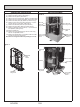
15. Removing the reactor (DCL)
(1) Remove the service panel. (See Photo 1)
(2) Remove the top panel. (See Photo 1)
(3) Remove the electrical parts box (See Photo 5)
(4) Remove 6 screws (4 x 10) for reactor to remove the
reactors. (See Figure 3)
Figure 3
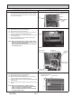
16. Removing the base heater
(1) Remove the service panel. (See Photo 1)
(2) Remove the top panel. (See Photo 1)
(3) Remove 4 fan grille fixing screws (5 × 12) to detach the
fan grille. (See Photo 1)
(4) Remove a nut (for right handed screw of M6) to detach
the propeller. (See Photo 2)
(5) Remove all of the following connectors from multi control-
ler circuit board;
<Diagram symbol in the connector housing>
• Fan motor (CNF1, CNF2)
• Base heater (SS)
Pull out the disconnected wire from the electrical parts
box. (See Photo 4)
(6) Loosen the wire clamps on the side of the motor support
and separator.
(7) Remove 2 motor support fixing screws (5 x 12), then
remove the motor support with fan motor still attached.
(See Photo 16)
(8) Remove 4 base heater cover fixing screws (4 x 10), then
remove the base heater cover.
(9) Remove the base heater. (See Photo 17)
Notes:
1. Tighten the propeller fan with a torque of 5.7 ± 0.3
N·m [4.2 ± 0.2 ft = lbs]
2. Rotate the propeller fan and make sure that the base
heater and the lead wires do not interfere with the
movement of the propeller fan.
Photo 16
Photo 17
Motor support xing screws
Base heater cover
xing screws
Motor support
Base heater cover
Base heater
Clamps
Separator
Reactors
Screws for
reactors