
MSZ-FS Installation Manual


5-3. PUMPING DOWN
When relocating or disposing of the air conditioner, pump down the system following
the procedure below so that refrigerant is not released into the atmosphere.
1) Connect the gauge manifold valve to the service port of the stop valve on the gas pipe
side of the outdoor unit.
2) Fully close the stop valve on the liquid pipe side of the outdoor unit.
3) Close the stop valve on the gas pipe side of the outdoor unit almost completely so that
it can be easily closed fully when the pressure gauge shows 0 psi [Gauge] (0 Mpa).
4) Start the emergency COOL operation.
To start the emergency operation in COOL mode, disconnect the power supply plug
and/or turn off the breaker. After 15 seconds, connect the power supply plug and/or turn
on the breaker, and then press the E.O. SW once. (The emergency COOL operation
can be performed continuously for up to 30 minutes.)
5) Fully close the stop valve on the gas pipe side of the outdoor unit when the pressure
gauge shows (0.1 to 0 psi [Gauge] (0.05 to 0 Mpa)).
6) Stop the emergency COOL operation.
To stop operation, press the E.O. SW several times until all LED lamps turn off. Refer
to operating instructions for details.
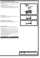
5-2. REMOVING THE INDOOR UNIT
Remove the bottom of the indoor unit from the installation plate.
When releasing the corner part, release both left and right bottom corner part of indoor
XQLWDQGSXOOLWGRZQZDUGDQGIRUZDUGDVVKRZQLQWKH¿JXUHRQWKHULJKW
Installation procedure
1) Install the panel assembly following the removal procedure in reverse.
2) Be sure to press the positions as indicated by the arrows in order to attach the assembly
completely to the unit.
3) Install the front panel and the horizontal vanes.
HEAD OFFICE: TOKYO BUILDING, 2-7-3, MARUNOUCHI, CHIYODA-KU,
TOKYO 100-8310, JAPAN
Upper and
lower vanes
Unlock
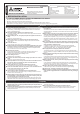
WARNING
When pumping down the refrigerant, stop the compressor before disconnecting
the refrigerant pipes. The compressor may burst if air etc. get into it.
5. RELOCATION AND MAINTENANCE
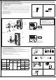
Removal procedure
1) Unlock the upper and lower vanes as shown in
and using a thin instrument.
Then, remove the horizontal vanes.
2) Remove the front panel.
5HPRYHWKHVFUHZVZKLFK¿[WKHSDQHODVVHPEO\
4) The panel assembly consists of 3 components. Remove them in the following order:
right, left, and center bottom. To remove the right component, pull out the right top
corner. To remove the left component, pull out the left bottom corner. To remove the
center bottom component, detach the hook on its upper center part.
5-1. REMOVING AND INSTALLING THE PANEL ASSEMBLY