
MXZ-SM48NAM Service Manual


138
OCH789
9-5. SYSTEM SWITCH SETTING
In order to identify the destinations of signals to the outdoor units, indoor units, and remote controller of MULTI-S series,
each microprocessor must be assigned an identification number (address). The addresses of outdoor units, indoor units, and
remote controller must be set using their settings switches. Please consult the installation manual that comes with each unit for
detailed information on setting procedures.
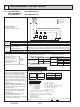
9-6. EXAMPLE EXTERNAL WIRING DIAGRAM FOR A BASIC SYSTEM
Outdoor
unit
Group operation
Remote controller wire
Pull box
Indoor unit
Breaker for Wiring
and Current Leakage
(If you use)
1.25 mm
2
× 2
Outdoor
unit
Pull box
1.25 mm
2
or more
(Shield cable)
■ Example of system when using a Branch Box
■ Example of system when using an M-NET controller
<When power is supplied to outdoor unit and branch box separately>
Transmission cable
Branch Box
A-control
indoor unit
MA
RC
A-control
indoor unit
MA
RC
A-control
indoor unit
MA
RC
Outdoor
unit
Branch Box
A-control
indoor unit
MA
RC
A-control
indoor unit
MA
RC
<When power is supplied to branch box from the outdoor unit>
B1
B2
;
Branch Box
A-control
indoor unit
MA
RC
A-control
indoor unit
MA
RC
A-control
indoor unit
MA
RC
Power supply
single phase
208
/
230 V AC 60 Hz
Power supply
single phase
208
/
230 V AC 60 Hz
Breaker for Wiring
and Current Leakage
(If you use)
Breaker for Wiring
and Current Leakage
(If you use)
Breaker for Wiring
and Current Leakage
(If you use)
Power supply
single phase
208
/
230 V AC 60 Hz
Power supply
single phase
208
/
230 V AC 60 Hz
Breaker for Wiring
and Current Leakage
(If you use)
Power supply
single phase
208
/
230 V AC 60 Hz
Branch Box
A-control
indoor unit
MA
RC
A-control
indoor unit
MA
RC