
MXZ-SM48NAMHZ Service Manual


149
OCH789
From the previous page.
OPERATING PROCEDURE PHOTOS/FIGURES
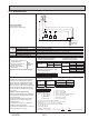
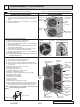
(6) Remove 2 electrical parts box fixing screws (4 × 10) and
detach the electrical parts box by pulling it upward.
The electrical parts box is fixed with 2 hooks on the left
and 1 hook on the right.
Photo 5
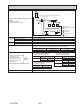
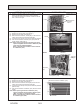
4. Removing the thermistor <Suction pipe> (TH6)
(1) Remove the service panel. (See Photo 1)
(2) Remove the top panel. (See Photo 1)
(3) Disconnect the connector, TH7/6 (red), on the multi con-
troller circuit board in the electrical parts box.
(4) Loosen the wire clamps on top of the electrical parts box.
(5) Pull out the thermistor <Suction pipe> (TH6) from the
sensor holder. (See Photo 7)
Note: When replacing thermistor <Suction pipe> (TH6),
replace it together with thermistor <Ambient> (TH7)
since they are combined together.
Refer to procedure No.5 below to remove thermis-
tor <Ambient> (TH7).
Photo 6
Photo 7
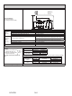
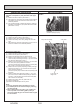
5. Removing the thermistor <Ambient> (TH7)
(1) Remove the service panel. (See Photo 1)
(2) Remove the top panel. (See Photo 1)
(3) Disconnect the connector TH7/6 (red) on the multi con-
troller circuit board in the electrical parts box.
(4) Loosen the wire clamps on top of the electrical parts box.
(See Photo 6)
(5) Pull out the thermistor <Ambient> (TH7) from the sensor
holder.
Note: When replacing thermistor <Ambient> (TH7),
replace it together with thermistor <Suction pipe>
(TH6), since they are combined together.
Refer to procedure No.4 above to remove thermis-
tor <Suction pipe> (TH6).
Photo 8
Lead wire of thermistor <Ambient> (TH7)
Electrical parts box
Clamps
Electrical parts box
Electrical parts
box xing
screws
Hook
Hooks
Sensor holder
Compressor
(MC)
Thermistor
<Suction pipe> (TH6)
Thermistor
<Compressor> (TH4)
Thermistor
<Hic pipe>
(TH2)
Ball valve and stop
valve fixing screws