
MXZ-SM48NAMHZ Service Manual


163
OCH789
OPERATING PROCEDURE PHOTOS/FIGURES
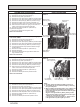
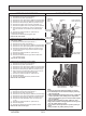
9. Removing bypass valve coil (SV1, SV2) and bypass valve
(1) Remove the service panel. (See Photo 1)
(2) Remove the top panel. (See Photo 1)
(3) Remove the cover panel (front). (Refer to procedure 8(5))
(4) Remove the cover panel (rear) (Refer to procedure 8(6))
(5) Remove the side panel (R). (Refer to procedure 8 (7))
(6) Remove the bypass valve coil fixing screw (M4 × 6).
(7) Remove the bypass valve coil by sliding the coil upward.
(8) Disconnect the connector SV1 (gray) or SV2 (blue) on
the multi controller circuit board in the electrical parts
box.
(9) Remove the electrical parts box. (See Photo 5)
(10) Recover refrigerant.
(11) Remove the welded part of bypass valve.
Refer to the notes below.
Photo 11
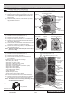
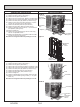
10. Removing the high pressure switch (63H) and high pres-
sure sensor (63HS)
(1) Remove the service panel. (See Photo 1)
(2) Remove the top panel. (See Photo 1)
(3) Remove the cover panel (front). (Refer to procedure 8(5))
(4) Remove the cover panel (rear) (Refer to procedure 8(6))
(5) Remove the side panel (R). (Refer to procedure 8 (7))
(6) Pull out the lead wire of high pressure switch and high
pressure sensor.
(7) Remove the electrical parts box. (See Photo 5)
(8) Recover refrigerant.
(9) Remove the welded part of high pressure switch and
high pressure sensor.
Refer to the notes below.
11. Removing the low pressure sensor (63LS)
(1) Remove the service panel. (See Photo 1)
(2) Remove the top panel. (See Photo 1)
(3) Remove the cover panel (front). (Refer to procedure 8(5))
(4) Remove the cover panel (rear) (Refer to procedure 8(6))
(5) Remove the side panel (R). (Refer to procedure 8 (7))
(6) Disconnect the connector 63LS (blue) on the multi con-
troller circuit board in the electrical parts box.
(7) Remove the electrical parts box. (See Photo 5)
(8) Recover refrigerant.
(9) Remove the welded part of low pressure sensor.
Refer to the notes below.
Photo 12
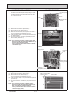
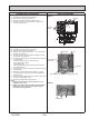
12. Removing linear expansion valve (LEV-A, LEV-B)
(1) Remove the service panel. (See Photo 1)
(2) Remove the top panel. (See Photo 1)
(3) Remove the cover panel (front). (Refer to procedure 8(5))
(4) Remove the cover panel (rear) (Refer to procedure 8(6))
(5) Remove the side panel (R). (Refer to procedure 8 (7))
(6) Remove the linear expansion valve coil. (See Photo
11,12)
(7) Remove the electrical parts box. (See Photo 5)
(8) Recover refrigerant.
(9) Remove the welded part of linear expansion valve.
Refer to the notes on the right.
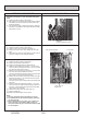
Notes:
1. Recover refrigerant without spreading it in the air.
2. The welded part can be removed easily by removing
the side panel (R).
3. When installing the following parts, cover it with a wet
cloth to prevent it from heating as the temperature
below, then braze the pipes so that the inside of pipes
are not oxidized;
• Bypass valve (procedure 9), 248°F [120°C] or more
• High pressure switch and high pressure sensor (proce-
dure 10), 212°F [100°C] or more
• Low pressure sensor (procedure 11), 212°F [100°C] or
more
• LEV (procedure 12), 248°F [120°C] or more
High pressure
sensor (63HS)
High pressure
switch (63H)
Low pressure
sensor (63LS)
Bypass valve
coil fixing screw
Linear expansion
valve coil (LEV-A)
Bypass valve
coil (SV1)
Bypass valve
Linear
expansion
valve
Switching
valve
Switching
valve coil
(SV2)
Linear expansion
valve coil (LEV-B)
Linear expansion
valve