
MXZ-SM48NAMHZ Service Manual


51
OCH789
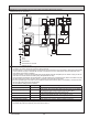
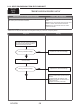
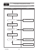
D. Example of a group operation with 2 or more outdoor units and an MA remote controller.
(Address settings are necessary.)
Examples of Transmission Cable Wiring
Wiring Method Address Settings
a. Always use shielded wire when making connections between the outdoor unit (OC) and the CITY MULTI series indoor
unit (M-IC), as well for all OC-OC, and IC-IC wiring intervals.
b.
Use feed wiring to connect terminals M1 and M2 and the ground terminal on the transmission cable terminal block (TB3)
of each outdoor unit (OC) to terminals M1 and M2 on the terminal S on the transmission cable terminal block of the
CITY MULTI series indoor unit (M-IC).
c.
Connect terminals 1 and 2 on the terminal block for MA remote controller line (TB15) on the indoor unit (IC) to the ter-
minal block on the MA remote controller (MA). (Nonpolarized two-wire).
d.
Connect together terminals M1, M2 and terminal S on the terminal block for centralized control (TB7) for the outdoor unit (OC).
e. DO NOT change the jumper connector CN41 on outdoor multi controller circuit board.
f. The earth processing of S terminal for the centralized control terminal block (TB7) is unnecessary. Connect the termi-
nal S on the power supply unit with the earth.
g. Set the address setting switch as follows.
h. The group setting operations among the multiple CITY MULTI series indoor unit is done by the M-NET remote control-
ler (M-NET RC) after the electrical power has been turned on.
TB7
M-IC
(51)
TB15 TB15
TB15
MA-RC
(01)
M-IC
TB5
(03)
M-IC
TB5TB5
(02)
M-IC
TB5
(04)
M-IC
(05)
M-IC
(07)
M-IC
(06)
L1
MA-RC
MA-RC
MA-RC
OC
(53)
OC
1
Power Supply
Unit
L3
L6
L4
m3
m3
1
1
2
2
TB3
: Group
: Group
: Group
: Shielded Wire
: Sub MA Remote Controller
( ): Address example
m
m
m
m
m
M1 M2
S
M1 M2
S
TB7
M1 M2
S
M1 M2
S
TB3
M1 M2
S
M1 M2
S
M1 M2
S
M1 M2
S
M1 M2
S
A B
1 2
1 2
M1 M2
S
1 2
1 2
TB15
TB5
M1 M2
S
1 2
TB15
TB5
M1 M2
S
1 2
A B A B
TB15
TB5
M1 M2
S
1 2
TB15
A B
L2
L5
System
controller
NO
4
m
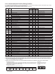
Unit Range Setting Method
M-IC (Main) 01 to 50
Use the smallest address within the same group of indoor units.
M-IC (Sub) 01 to 50
Use an address, other than the M-IC (Main) in the same group of CITY MULTI
series indoor units. This must be in sequence with the M-IC (Main).
Outdoor Unit 51 to 100
Use the smallest address of all the indoor units plus 50.
The address automatically becomes “100” if it is set as “01–50”.
Main M-NET Remote Controller
101 to 150
Set at an M-IC (Main) address within the same group plus 100.
Sub M-NET Remote Controller
151 to 200
Set at an M-IC (Main) address within the same group plus 150.
MA Remote Controller —
Address setting is not necessary. (Main/sub setting is necessary.)