Revision D: • MUZ-GL24NAH- U1 has been added. OBH733 REVISED EDITION-C is void. OUTDOOR INDOOR UNIT UNIT HFC utilized SERVICE MANUAL No.
Use the specified refrigerant only Never use any refrigerant other than that specified. Doing so may cause a burst, an explosion, or fire when the unit is being used, serviced, or disposed of. Correct refrigerant is specified in the manuals and on the spec labels provided with our products. We will not be held responsible for mechanical failure, system malfunction, unit breakdown or accidents caused by failure to follow the instructions.
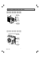
2 PART NAMES AND FUNCTIONS MUZ-GL09NA MUZ-GL09NAH MUY-GL09NA MUZ-GL12NA MUZ-GL12NAH MUY-GL12NA MUZ-GL15NA MUZ-GL15NAH MUY-GL15NA Air inlet (back and side) Piping Air outlet Drain hose Drain outlet MUZ-GL18NA MUZ-GL18NAH MUY-GL18NA MUZ-GL24NA MUZ-GL24NAH MUY-GL24NA Air inlet (back and side) Piping Drain hose Air outlet Drain outlet OBH733D 3
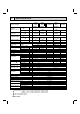
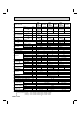
3 SPECIFICATION MUZGL09NAMUZGL09NAH- Outdoor unit model Capacity Rated (Minimum~Maximum) Capacity Rated (Maximum) Power consumption Rated (Minimum~Maximum) Cooling 1 Btu/h Heating 47 1 (MUZ) Btu/h Heating 17 2 (MUZ) Btu/h Cooling 1 U1 Heating 47 1 (MUZ) W Cooling MUZGL09NAMUZGL09NAH- U8 MUYGL09NA U8 9,000 (3,600 - 12,200) 10,900 (4,500 - 15,900) 6,700 (10,200) W Power consumption Heating 17 2 (MUZ) W Rated (Maximum) EER 1 [SEER] 3 U1 10,900 (4,500 - 14,100) 7,000 (9,400) 720 (230 - 1,07
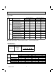
Outdoor unit model Capacity Rated (Minimum~Maximum) Capacity Rated (Maximum) Power consumption Rated (Minimum~Maximum) Cooling 1 Btu/h Heating 47 1 (MUZ) Btu/h Heating 17 2 (MUZ) Btu/h Cooling 1 W Heating 47 1 (MUZ) W MUZGL15NA MUYMUZGL15NA GL15NAH 14,000 (3,100 - 18,200) 18,000 (4,800 - 20,900) 12,200 (16,400) 1,080 (210 - 2,000) 1,600 (2,010) 1,190 (1,850) 13.0 [21.6] NA: 11.7 NAH: 10.8 3.
Test condition 3, 4 ARI Mode Indoor air condition (°F) Dry bulb Wet bulb Test Outdoor air condition (°F) Dry bulb Wet bulb "A-2" Cooling Steady State at rated compressor Speed 80 67 95 (75) "B-2" Cooling Steady State at rated compressor Speed 80 67 82 (65) SEER "B-1" Cooling Steady State (Cooling) at minimum compressor Speed 80 67 82 (65) "F-1" Cooling Steady State at minimum compressor Speed 80 67 67 (53.
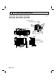
4 OUTLINES AND DIMENSIONS Unit: inch MUZ-GL09NA MUZ-GL09NAH MUY-GL09NA MUZ-GL12NA MUZ-GL12NAH MUY-GL12NA MUZ-GL15NA MUZ-GL15NAH MUY-GL15NA *1 4 in. (100 mm) or more when front and sides of the unit are clear clear *1 REQUIRED SPACE 4 in .( or 100 m mo re m) ) mm 00 re 1 ( o n. 4 i or m (GL09/12/15NA) (GL09/12/15NAH) ) mm 00 . (2 ore *2 n i 8 rm o 14 in.
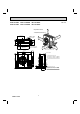
MUZ-GL18NA MUZ-GL24NA MUZ-GL18NAH MUZ-GL24NAH MUY-GL18NA MUY-GL24NA Unit: inch Clear *1 REQUIRED SPACE *1 20 in. (500 mm) or more when front and sides of the unit are clear 16-7/16 2 13 Drain hole 1-9/16 ) mm 00 . (1 re n i 4 mo or 1-5/8 4i or mn. (10 ore 0 mm ) 14-3/16 Air in Air in ) mm 500 ( . 2 in 20 ore * or m Air out 2-holes 13/32 13/16 6-7/8 19-11/16 14 or min.
5 WIRING DIAGRAM MUZ-GL09NA MUZ-GL12NA OBH733D 9
MUZ-GL09NAH MUZ-GL12NAH OBH733D 10
MUY-GL09NA MUY-GL12NA OBH733D 11
MUZ-GL15NA OBH733D 12
MUZ-GL15NAH OBH733D 13
MUY-GL15NA OBH733D 14
MUZ-GL18NA OBH733D 15
MUZ-GL18NAH OBH733D 16
MUY-GL18NA OBH733D 17
MUZ-GL24NA OBH733D 18
MUZ-GL24NAH OBH733D 19
MUY-GL24NA OBH733D 20
6 REFRIGERANT SYSTEM DIAGRAM Unit: Inch (mm) MUZ-GL09NA MUZ-GL09NAH MUY-GL09NA MUZ-GL12NA MUZ-GL12NAH MUY-GL12NA MUZ-GL15NA MUZ-GL15NAH MUY-GL15NA Refrigerant pipe ø3/8 (ø9.52) (GL09/12) ø1/2 (ø12.7) (GL15) (with heat insulator) 4-way valve Muffler Stop valve (with service port) Flared connection Service port Outdoor heat exchanger Muffler Discharge temperature thermistor RT62 Service port Ambient temperature thermistor RT65 Compressor Defrost thermistor RT61 (MUZ) Capillary tube O.D. 0.
MUZ-GL24NA MUY-GL24NA Refrigerant pipe ø5/8 (ø15.88) (with heat insulator) 4-way valve Muffler with #100 mesh strainer Service port Stop valve (with service port) Flared connection Service port Outdoor heat exchanger Discharge temperature thermistor RT62 Defrost thermistor RT61 (MUZ) Ambient temperature thermistor RT65 Compressor Outdoor heat exchanger temperature thermistor RT68 Flared connection LEV Strainer #100 Stop valve Refrigerant pipe ø3/8 (ø9.
MAX. REFRIGERANT PIPING LENGTH and MAX. HEIGHT DIFFERENCE Model MUZ-GL09NA MUZ-GL09NAH MUY-GL09NA MUZ-GL12NA MUZ-GL12NAH MUY-GL12NA MUZ-GL15NA MUZ-GL15NAH MUY-GL15NA MUZ-GL18NA MUZ-GL18NAH MUY-GL18NA MUZ-GL24NA MUZ-GL24NAH MUY-GL24NA Refrigerant piping: ft. Max. Length Max. Height difference A B Piping size O.D: in. Gas Liquid 3/8 65 40 1/4 1/2 100 50 5/8 3/8 Indoor unit Max. Height difference B Max. Length A Outdoor unit ADDITIONAL REFRIGERANT CHARGE (R410A: oz.
NOTE: Refrigerant piping exceeding 25 ft. requires additional refrigerant charge according to the calculation. Refrigerant piping length (one way): ft. 50 60 70 80 Model Outdoor unit precharged 25 30 40 MUZ-GL18NA MUZ-GL18NAH MUY-GL18NA 3 lb. 9 oz. 0 1.08 3.24 5.40 7.56 9.72 11.88 90 100 14.04 16.20 Calculation: X oz. = 1.08/5 oz./ft. × (Refrigerant piping length (ft.) - 25) NOTE: Refrigerant piping exceeding 33 ft. requires additional refrigerant charge according to the calculation.
7 DATA MUZ-GL09NA MUZ-GL12NA MUZ-GL15NA MUZ-GL18NA MUZ-GL24NA MUZ-GL09NAH MUZ-GL12NAH MUZ-GL15NAH MUZ-GL18NAH MUZ-GL24NAH MUY-GL09NA MUY-GL12NA MUY-GL15NA MUY-GL18NA MUY-GL24NA 7-1. PERFORMANCE DATA 1) COOLING CAPACITY Indoor air Model MUZ-GL09NA MUZ-GL09NAH MUY-GL09NA MUZ-GL12NA MUZ-GL12NAH MUY-GL12NA MUZ-GL15NA MUZ-GL15NAH MUY-GL15NA MUZ-GL18NA MUZ-GL18NAH MUY-GL18NA MUZ-GL24NA MUZ-GL24NAH MUY-GL24NA IWB (˚F) 71 67 63 71 67 63 71 67 63 71 67 63 71 67 63 TC 11.0 10.4 9.8 14.7 13.9 13.1 17.2 16.
3) HEATING CAPACITY (MUZ) Indoor air Model IDB (˚F) MUZ-GL09NA MUZ-GL12NA MUZ-GL09NAH MUZ-GL12NAH MUZ-GL15NA MUZ-GL15NAH MUZ-GL18NA MUZ-GL18NAH MUZ-GL24NA MUZ-GL24NAH 75 70 65 75 70 65 75 70 65 75 70 65 75 70 65 75 70 65 75 70 65 75 70 65 75 70 65 75 70 65 5 TC 4.8 5.2 5.5 6.3 6.8 7.2 4.8 5.2 5.5 6.3 6.8 7.2 7.9 8.6 9.0 7.9 8.6 9.0 9.5 10.3 10.8 9.5 10.3 10.8 12.1 13.1 13.8 12.1 13.1 13.8 15 TPC 0.42 0.41 0.39 0.65 0.62 0.59 0.55 0.54 0.52 0.78 0.75 0.72 0.94 0.90 0.86 1.07 1.03 0.99 0.99 0.
7-2. PERFORMANCE CURVE Cooling Cooling capacity (at Rated frequency) Capacity correction factors 1.5 Indoor intake air Wet-bulb temperature( F) 1.4 1.3 1.2 79 1.1 75 1.0 0.9 14 23 32 41 50 59 68 77 86 95 104 72 68 64 113 Outdoor intake air DB temperature(°F) SHF at rating condition = 0.82 Airflow = 399 CFM 71 67 63 0.6 0.5 rature 0.4 0.2 e air r intak 0.
Heating Heating capacity (at Rated frequency) 59 68 79 Capacity correction factor 1.3 1.2 ) ure (F rat 1.1 1.0 lb bu 0.9 ir ea tak 0.8 yDr e mp te in or o Ind 0.7 0.6 0.5 0.4 -4 5 14 23 32 41 50 Outdoor intake air WB temperature (°F) 59 MUZ-GL09NA MUZ-GL09NAH Airflow = 406 CFM Airflow = 406 CFM 75 70 65 F) ture (° mpera ir DB te a e k inta Indoor 5 15 25 35 45 55 Outdoor intake air WB temperature (°F) Total power consumption (kW) Total power consumption (kW) 1.0 0.9 0.8 0.
MUZ-GL18NA MUZ-GL18NAH Airflow = 646 CFM 75 70 65 1.8 1.6 1.4 (°F) erature B temp D ir a intake Indoor 1.2 1.0 0.8 0.6 -5 5 15 25 35 45 55 Outdoor intake air WB temperature (°F) 65 Total power consumption (kW) MUZ-GL24NA Airflow = 738 CFM 2.6 2.2 1.8 take air Indoor in 0 75 70 65 1.6 1.3 0.7 F) rature (° B tempe take air D Indoor in 1.
7-3. CONDENSING PRESSURE Cooling Data are based on the condition of indoor humidity 50 %. Air flow should be set to High speed.
MUZ-GL18NA MUZ-GL18NAH MUY-GL18NA (PSIG) 500 ) (°F ture 86 80 75 70 a per 400 B or D tem 86 80 75 70 o Ind 350 300 250 200 65 (PSIG) 180 Suction pressure Condensing pressure 450 70 75 80 85 90 95 100 105 (°F) 160 140 120 rature (°F) Indoor DB tempe 100 80 65 70 Outdoor ambient temperature 75 80 85 90 95 Outdoor ambient temperature 100 105 (°F) MUZ-GL24NA MUZ-GL24NAH MUY-GL24NA (PSIG) 480 86 80 75 70 ure 420 F) (° t era 390 or DB p tem o Ind 360 330 300 270 68 70
Heating Data are based on the condition of outdoor humidity 75%. Air flow should be set to High speed. Data are for heating operation without any frost.
MUZ-GL15NA MUZ-GL15NAH (PSIG) 500 75 70 65 450 B te 165 Suction pressure D oor Ind 400 350 15 25 35 45 55 Outdoor ambient temperature 65 re (°F u at r pe m 115 or DB te o nd I 90 65 58Hz 5 ) 140 300 250 75 70 65 ) (°F e mp Condensing pressure re ratu (PSIG) 190 40 75 (°F) 58Hz 5 15 25 35 45 55 Outdoor ambient temperature 65 75 (°F) MUZ-GL18NA MUZ-GL18NAH (PSIG) 550 (PSIG) 200 175 450 ture 75 70 65 ) (°F a per oor 400 Ind DB tem 350 300 250 Suction
7-4. STANDARD OPERATION DATA Model MSZ-GL09NA - U1 Item Total Capacity Cooling Heating Cooling Heating Cooling Btu/h 9,000 10,900 9,000 10,900 9,000 SHF — 0.82 — 0.82 — 0.82 Input kW 0.585 0.72 0.585 0.72 0.585 Rated frequency Hz 59 73 48 59 59.5 MSZ-GL09NA V, phase, Hz Electrical circuit Power supply Input Fan motor current Refrigerant circuit MSY-GL09NA 208/230, 1, 60 0.022 0.023 0.022 0.023 0.022 A 0.24/0.22 0.25/0.23 0.24/0.22 0.25/0.23 0.24/0.
Unit MSZ-GL12NA MSY-GL12NA Cooling Heating MSZ-GL15NA MSY-GL15NA Cooling Heating Model Item Total Capacity Btu/h 12,000 14,400 14,000 18,000 SHF — 0.77 — 0.78 — Input kW 0.920 1.10 1.080 1.60 Rated frequency Hz 70 77 56.5 74 MSZ-GL12NA MSY-GL12NA Indoor unit V, phase, Hz Electrical circuit Power supply Input Fan motor current 208/230, 1, 60 kW 0.022 0.023 0.043 0.030 A 0.24/0.22 0.25/0.23 0.43/0.39 0.34/0.
Unit MSZ-GL18NA MSY-GL18NA Cooling Heating MSZ-GL24NA MSY-GL24NA Cooling Heating Model Item Total Capacity Btu/h 18,000 21,600 22,500 27,600 SHF — 0.87 — 0.75 — Input kW 1.34 1.68 1.80 2.34 Rated frequency Hz 69 81 67.5 82.0 MSZ-GL18NA MSY-GL18NA Indoor unit V, phase, Hz Electrical circuit Power supply Input Fan motor current 0.045 A Outdoor unit 0.46/0.42 0.56/0.51 MUZ-GL18NA MUZ-GL18NAH MUY-GL18NA MUZ-GL24NA MUZ-GL24NAH MUY-GL24NA 208/230, 1, 60 kW 1.295 1.635 1.
7-5. CAPACITY AND INPUT CORRECTION BY INVERTER OUTPUT FREQUENCY MUZ-GL09NA - U1 MUZ-GL09NAH- U1 Correction of Cooling total input 1.0 0.5 0 25 50 75 1.5 1.0 0.5 0 100 (Hz) The operational frequency of compressor 2.0 2.0 Capacity correction factors Input correction factors Capacity correction factors 1.5 Correction of Heating total input Correction of Heating capacity 2.0 25 50 75 Input correction factors Correction of Cooling capacity 2.0 1.5 1.0 0.
MUZ-GL15NA MUZ-GL15NAH MUY-GL15NA Correction of Cooling capacity Correction of Cooling total input 0.5 0 25 50 75 100 (Hz) The operational frequency of compressor 1.5 1.0 0.5 0 25 50 75 2.0 Input correction factors 1.0 2.0 Capacity correction factors 1.5 Correction of Heating total input Correction of Heating capacity 2.0 Input correction factors Capacity correction factors 2.0 1.5 1.0 0.5 100 (Hz) 0 The operational frequency of compressor 50 1.5 1.0 0.
8 ACTUATOR CONTROL MUZ-GL09NA MUZ-GL12NA MUZ-GL15NA MUZ-GL18NA MUZ-GL24NA MUZ-GL09NAH MUZ-GL12NAH MUZ-GL15NAH MUZ-GL18NAH MUZ-GL24NAH MUY-GL09NA MUY-GL12NA MUY-GL15NA MUY-GL18NA MUY-GL24NA 8-1. OUTDOOR FAN MOTOR CONTROL The fan motor turns ON/OFF, interlocking with the compressor. [ON] The fan motor turns ON 5 seconds before the compressor starts up. [OFF] The fan motor turns OFF 15 seconds after the compressor has stopped running. 5 seconds 15 seconds ON Compressor OFF ON Outdoor fan motor OFF 8-2.
9 SERVICE FUNCTIONS MUZ-GL09NA MUZ-GL12NA MUZ-GL15NA MUZ-GL18NA MUZ-GL24NA MUZ-GL09NAH MUZ-GL12NAH MUZ-GL15NAH MUZ-GL18NAH MUZ-GL24NAH MUY-GL09NA MUY-GL12NA MUY-GL15NA MUY-GL18NA MUY-GL24NA 9-1. CHANGE IN DEFROST SETTING (MUZ) Changing defrost finish temperature To change the defrost finish temperature, cut/solder the JS wire of the outdoor inverter P.C. board (Refer to 10-6.1.).
10 TROUBLESHOOTING MUZ-GL09NA MUZ-GL12NA MUZ-GL15NA MUZ-GL18NA MUZ-GL24NA MUZ-GL09NAH MUZ-GL12NAH MUZ-GL15NAH MUZ-GL18NAH MUZ-GL24NAH MUY-GL09NA MUY-GL12NA MUY-GL15NA MUY-GL18NA MUY-GL24NA 10-1. CAUTIONS ON TROUBLESHOOTING 1. Before troubleshooting, check the following 1) Check the power supply voltage. 2) Check the indoor/outdoor connecting wire for miswiring. 2.
10-2. FAILURE MODE RECALL FUNCTION Outline of the function This air conditioner can memorize the abnormal condition which has occurred once. Even though LED indication listed on the troubleshooting check table (10-3.) disappears, the memorized failure details can be recalled. 1.
2. Flow chart of the detailed outdoor unit failure mode recall function Operational procedure The outdoor unit might be abnormal. Check if outdoor unit is abnormal according to the following procedures. Make sure that the remote controller is set to the failure mode recall function. With the remote controller headed towards the indoor unit, press TOO COOL button to adjust the set temperature to 77°F (25°C).
NOTE: Blinking patterns of this mode differ from the ones of TROUBLESHOOTING CHECK TABLE (10-3.). 3. Outdoor unit failure recall mode table The upper lamp of the OPERATION INDICATOR lamp (Indoor unit) OFF 1-time flash 2.5 seconds OFF Abnormal point (Failure mode/protection) None (Normal) Indoor/outdoor communication, receiving error Indoor/outdoor communication, receiving error LED indication (Outdoor P.C. board) — — — 2-time flash 2.5 seconds OFF Outdoor power system 3-time flash 2.
NOTE: Blinking patterns of this mode differ from the ones of TROUBLESHOOTING CHECK TABLE (10-3.). The upper lamp of the Abnormal point OPERATION (Failure mode/protection) INDICATOR lamp (Indoor unit) 10-time flash Discharge temperature 2.5 seconds OFF 11-time flash 2.5 seconds OFF 14-time flash or more 2.5 seconds OFF DC voltage Each phase current of compressor Stop valve (Closed valve) LED indication (Outdoor P.C. board) — 8-time flash 2.5 seconds OFF 9-time flash 2.5 seconds OFF 14-time flash 2.
10-3. TROUBLESHOOTING CHECK TABLE No. 1 Symptom Outdoor unit does not operate. Abnormal point/ Condition 1-time flash every Outdoor power sys2.5 seconds tem 4 5 6 7 8 9 Remedy • Reconnect connector of compressor. • Refer to 10-5. "How to check inverter/compressor". • Check stop valve. Outdoor thermistors Discharge temperature thermistor, fin temperature thermistor, • Refer to 10-5. "Check of outdoor defrost thermistor, P.C. board temperature thermistor, outdoor thermistors".
No. Symptom Outdoor unit operates. LED indication 1-time flash 2.5 seconds OFF Abnormal point/ Condition Frequency drop by current protection 16 Current from power outlet is nearing breaker capacity. Frequency drop by defrosting in COOL mode Indoor coil thermistor reads 46°F (8°C) or less in COOL mode, compressor frequency lowers. 4-time flash 2.
10-4. TROUBLE CRITERION OF MAIN PARTS MUZ-GL09NA MUZ-GL12NA MUZ-GL15NA MUZ-GL18NA MUZ-GL24NA MUZ-GL09NAH MUZ-GL12NAH MUZ-GL15NAH MUZ-GL18NAH MUZ-GL24NAH MUY-GL09NA MUY-GL12NA MUY-GL15NA MUY-GL18NA MUY-GL24NA Part name Defrost thermistor (RT61) (MUZ) Check method and criterion Figure Fin temperature thermistor (RT64) Measure the resistance with a tester. Ambient temperature thermistor (RT65) Refer to 10-6. “Test point diagram and voltage”, 1. “Inverter P.C. board”, for the chart of thermistor.
10-5. TROUBLESHOOTING FLOW A How to check inverter/compressor Disconnect the connector between the compressor and the power module (IC700) (MUZ-GL09/12/15/18, MUY-GL09/12/15/18)/IGBT module (IC700) (MUZGL24, MUY-GL24). See 10-5. Check the voltage between terminals. Are the voltages balanced? Yes No Replace the inverter P.C. board. See 10-5. Check the compressor. “Check of open phase”. “Check of compressor”.
D Check of compressor winding ●Disconnect the connector between the compressor and the power module (IC700) (MUZ-GL09/12/15/18, MUY-GL09/12/15/18)/ IGBT module (IC700) (MUZ-GL24, MUY-GL24), and measure the resistance between the compressor terminals. <> At 3 points BLK-WHT Measure the resistance between the lead wires at 3 points. BLK-RED WHT-RED <> Refer to 10-4.
G Check of outdoor thermistors Disconnect the connector of thermistor in the inverter P.C. board (see below table), and measure the resistance of thermistor. Is the resistance of thermistor normal? (Refer to 10-6.1.) Yes No Replace the thermistor except RT64. When RT64 is abnormal, replace the inverter P.C. board. Reconnect the connector of thermistor. Turn ON the power supply and press EMERGENCY OPERATION switch.
H Check of R.V. coil (MUZ) MUZ-GL09/12/15/18NA MUZ-GL09/12/15/18NAH First of all, measure the resistance of R.V. coil to check if the coil is defective. Refer to 10-4. In case CN721 is disconnected or R.V. coil is open, voltage is generated between the terminal pins of the connector although no signal is being transmitted to R.V. coil. Check if CN721 is connected. Unit operates COOL mode even if it is set to HEAT mode. Disconnect connector between the compressor and the power module (IC700).
I Check of outdoor fan motor Check the connection between the connector CN931 and CN932. Disconnect the connectors CN931 and CN932 from the inverter P.C. board. Is the resistance between each terminal of outdoor fan motor normal? (Refer to 10-4.) No Yes Disconnect CN932 from the inverter P.C. board, and turn on the power supply. Rotate the outdoor fan motor manually and measure the voltage of CN931.
J Check of power supply Disconnect the connector between the compressor and the power module (IC700) (MUZ-GL09/12/15/18, MUYGL09/12/15/18)/IGBT module (IC700) (MUZ-GL24, MUY-GL24). Turn ON power supply and press EMERGENCY OPERATION switch. Does the upper lamp of the OPERATION INDICATOR lamp on the indoor unit light up? Yes Is there DC voltage 260 - 370 VDC between DB61 (+) and DB61 (–) (MUZ-GL09/12/15/18, MUYGL09/12/15/18)/294 - 370 VDC between JP715 (+) and JP30 (–) (MUZ-GL24, MUY-GL24) on the inverter P.
K Check of LEV (Expansion valve) Turn ON the power supply. While pressing both OPERATION SELECT button and TOO COOL button on the remote controller at the same time, press RESET button. First, release RESET button. Hold down the other 2 buttons for another 3 seconds. Make sure that the indicators on the LCD screen shown in the right figure are all displayed. Then release the buttons.
L Check of inverter P.C. board Check the outdoor fan motor. (Refer to 10-5. .) Is the fuse (F901) blown on the inverter P.C. board? No Yes Check the connection of the connectors (CN931, CN932) of the outdoor fan motor. If the connection is poor, make it correct. Operate the outdoor unit by starting EMERGENCY OPERATION. Check the LED indication on the inverter P.C. board. Does the LED flash 10 times? Yes (10-time flash) No Check the corresponding parts following LED indication. (Refer to 10-3.
M How to check miswiring and serial signal error MUZ-GL09/12/15NA MUZ-GL09/12/15NAH MUY-GL09/12/15NA Turn OFF the power supply. Is there rated voltage in the power supply? Yes Check the power supply. No Turn ON the power supply. Is there rated voltage between the outdoor terminal block S1 and S2? Yes No Check the wiring. Press EMERGENCY OPERATION switch once.
MUZ-GL18/24NA MUZ-GL18/24NAH MUY-GL18/24NA Turn OFF the power supply. Is there rated voltage in the power supply? Yes Check the power supply. No Turn ON the power supply. No Is there rated voltage between outdoor terminal block S1 and S2? Yes Check the wiring. Press EMERGENCY OPERATION switch once. Does the OPERATION INDICATOR lamp light up? Yes Is serial signal error indicated 6 minutes later? Yes A Turn OFF the power supply.
N Check of defrost heater (base pan heater) (MUZ-GL•NAH) MUZ-GL09/12/15/18/24NAH Check the following points before checking electric continuity. 1. Does the resistance of ambient temperature thermistor have the characteristics? Refer to 10-6.1. 2. Is the resistance of defrost heater normal? Refer to 10-4. 3. Does the heater protector remain conducted (not open)? 4.
P Electromagnetic noise enters into TV sets or radios Is the unit grounded? Yes Is the distance between the antennas and the indoor unit within 9.91 ft. (3m), or is the distance between the antennas and the outdoor unit within 9.91 ft. (3m)? No Is the distance between the TV sets or radios and the indoor unit within 3.28 ft. (1m), or is the distance between the TV sets or radios and the outdoor unit within 9.91 ft. (3m)? Ground the unit.
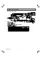
10-6. TEST POINT DIAGRAM AND VOLTAGE 1. Inverter P.C. board MUZ-GL09/12/15NA MUZ-GL09/12/15NAH MUY-GL09/12/15NA Smoothing capacitor (C63) DB61 260 - 370 VDC (-) (+) Back side of unit Smoothing capacitor (C62) R.V.coil Heater connector (CN721) (CN722) (MUZ) Smoothing (MUZ-GL09/ capacitor (C61) 208/230 VAC 12/15NAH) Fuse (F701) T3.15AL250V Fuse (F801) T3.15AL250V 208/230 VAC Fuse (F901) T3.
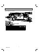
MUZ-GL18NA MUZ-GL18NAH MUY-GL18NA Back side of unit Smoothing capacitor (C63) Smoothing capacitor (C62) DB61 260 - 370 VDC (-) (+) R.V.coil (CN721) (MUZ) 208/230 VAC Heater connector (CN722) (MUZ-GL18NAH) Fuse (F701) T3.15AL250V Smoothing capacitor (C61) Fuse (F801) T3.15AL250V 208/230 VAC Fuse (F901) T3.
MUZ-GL24NA MUZ-GL24NAH MUY-GL24NA Fuse (F601) T3.15AL250V R.V. coil (CN602) 208/230 VAC (MUZ) Heater connector (CN601) (MUZ-GL24NAH) Signal of outdoor fan motor (CN931) LEV connector (CN724) LED Defrost thermistor /RT61 (CN671) (MUZ) Discharge temperature thermistor/RT62 (CN671) Outdoor heat exchanger temperature thermistor /RT68 (CN671) Ambient temperature thermistor/RT65 (CN672) Fin temperature thermistor/RT64 (CN673) Jumper wire for changing defrost setting (JS) Fuse (F901) T3.
11 DISASSEMBLY INSTRUCTIONS <"Terminal with locking mechanism" Detaching points> The terminal which has the locking mechanism can be detached as shown below. There are 2 types (refer to (1) and (2)) of the terminal with locking mechanism. The terminal without locking mechanism can be detached by pulling it out. Check the shape of the terminal before detaching. (1) Slide the sleeve and check if there is a locking lever or not. (2) The terminal with this connector has the locking mechanism.
OPERATING PROCEDURE Photo 4 PHOTOS Photo 5 Screws of the conduit cover 2. Removing the inverter assembly, inverter P.C. board (1) Remove the cabinet and panels. (Refer to 1.) (2) Disconnect the lead wire to the reactor and the following connectors: CN721 (R.V.
OPERATING PROCEDURE PHOTOS 4. Removing the discharge temperature thermistor, defrost thermistor, outdoor heat exchanger temperature thermistor and ambient temperature thermistor Photo 8 Screw of the R.V. coil (MUZ) (1) Remove the cabinet and panels. (Refer to 1.) (2) Disconnect the lead wire to the reactor and the following connectors:
PHOTOS OPERATING PROCEDURE 5. Removing outdoor fan motor Photo 10 Screws of the outdoor fan motor (1) Remove the cabinet and panels. (Refer to 1.) (2) Disconnect the following connectors: CN931, CN932 (Fan motor) (3) Remove the propeller fan nut. (4) Remove the propeller fan. (5) Remove the screws fixing the fan motor. (6) Remove the fan motor. NOTE: The propeller fan nut is a revers thread. Propeller fan 6.
11-2. MUZ-GL18NA MUZ-GL18NAH MUY-GL18NA NOTE: Turn OFF the power supply before disassembly. OPERATING PROCEDURE PHOTOS 1. Removing the cabinet Photo 1 (1) Remove the screws of the service panel. (2) Remove the screws of the top panel. (3) Remove the screw of the valve cover. (4) Remove the service panel. (5) Remove the screws fixing the conduit cover. (6) Remove the conduit cover. (7) Remove the screw of fixing the conduit plate. (8) Remove the conduit plate. (9) Remove the top panel.
OPERATING PROCEDURE PHOTOS 2. Removing the inverter assembly, inverter P.C. board Photo 5 Screws of the terminal (1) Remove the cabinet and panels. (Refer to 1.) Screw of the heat sink block support and the (2) Disconnect the lead wire to the reactor and the following con- support and the separator back panel nectors: CN721 (R.V.
OPERATING PROCEDURE PHOTOS 4. Removing the discharge temperature thermistor, defrost thermistor (MUZ), outdoor heat exchanger temperature thermistor and ambient temperature thermistor Photo 8 Outdoor heat exchanger temperature thermistor Ambient temperature thermistor (1) Remove the cabinet and panels. (Refer to 1.) (2) Disconnect the lead wire to the reactor and the following connectors:
11-3. MUZ-GL24NA MUZ-GL24NAH MUY-GL24NA NOTE: Turn OFF the power supply before disassembly. OPERATING PROCEDURE PHOTOS 1. Removing the cabinet Photo 1 (1) (2) (3) (4) (5) (6) (7) (8) (9) Remove the screws of the service panel. Remove the screws of the top panel. Remove the screw of the valve cover. Remove the service panel. Remove the screws fixing the conduit cover. Remove the conduit cover. Remove the top panel. Remove the valve cover. Disconnect the power supply and indoor/outdoor connecting wire.
OPERATING PROCEDURE PHOTOS 2. Removing the inverter assembly, inverter P.C. board and relay P.C. board (1) Remove the cabinet and panels. (Refer to 1.) (2) Disconnect the lead wire to the reactor and the following connectors: CN601 (Defrost heater) (MUZ-GL24NAH) CN602 (R.V.
OPERATING PROCEDURE PHOTOS 4. Removing the discharge temperature thermistor, defrost thermistor (MUZ), outdoor heat exchanger temperature thermistor and ambient temperature thermistor Photo 7 Outdoor heat exchanger temperature thermistor Ambient temperature thermistor (1) Remove the cabinet and panels. (Refer to 1.) (2) Disconnect the lead wire to the reactor and the following connectors:
HEAD OFFICE: TOKYO BUILDING, 2-7-3, MARUNOUCHI, CHIYODA-KU, TOKYO 100-8310, JAPAN © Copyright 2015 MITSUBISHI ELECTRIC CORPORATION Issued: Mar. 2017. No. OBH733 REVISED EDITION-D Issued: Sep. 2016. No. OBH733 REVISED EDITION-C Issued: Jan. 2016. No. OBH733 REVISED EDITION-B Issued: Nov. 2015. No. OBH733 REVISED EDITION-A Published: Sep. 2015. No. OBH733 Made in Japan Specifications are subject to change without notice.