
Sales Fact Sheet

OPERATING PROCEDURE
PHOTOS
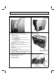
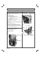
5. Removing outdoor fan motor
(1) Remove the cabinet and panels. (Refer to 1.)
(2) Disconnect the following connectors:
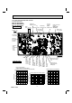
<Inverter P.C. board>
CN931, CN932 (Fan motor)
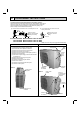
(3) Remove the propeller fan nut.
(4) Remove the propeller fan.
(5) Remove the screws fixing the fan motor.
(6) Remove the fan motor.
NOTE: The propeller fan nut is a revers thread.
Photo 10
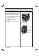
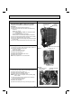
6. Removing the compressor and 4-way valve
(1) Remove the cabinet and panels. (Refer to 1.)
(2) Remove the inverter assembly. (Refer to 2.)
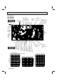
(3) Remove the screws fixing the reactor.
(4) Remove the reactor.
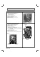
(5) Remove the soundproof felt.
(6) Recover gas from the refrigerant circuit.
NOTE: Recover gas from the pipes until the pressure gauge
shows 0 PSIG.
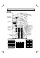
(7) Detach the brazed part of the suction and the discharge pipe
connected with compressor.
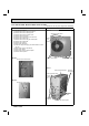
(8) Remove the nuts fixing the compressor.
(9) Remove the compressor.
(
10
) Detach the brazed part of pipes connected with 4-way valve.
Photo 12
Photo 11
67
Propeller fan nut
Screws of the outdoor fan motor
Propeller fan
Screws of
the reactor
Soundproof
felt
Brazed parts of
4-way valve
Discharge pipe
brazed part
Suction pipe
brazed part
OBH733D