MODELS MultiSync 75F-3 AccuSync 75F-3 (N0701-3) COLOR MONITOR SERVICE MANUAL Better Service Better Reputation Better Profit /MITSUBISHI NEC-MITSUBISHI ELECTRIC VISUAL SYSTEMS
! WARNING The SERVICE PERSONNEL should have the appropriate technical training knowledge and experience necessary to : Be familiar with specialized test equipment, and Be careful to follow all safety procedures associated with high voltage CRT circuit designs to minimize danger to themselves and their coworkers. To avoid electrical chocks, this equipment should be used with an appropriate power cord and be connected only to a properly grounded AC outlet This equipment utilized a micro-gap power switch.
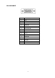
CONTENTS Page No. PRECAUTIONS ...................................................................................................................... 1 SPECIFICATIONS .................................................................................................................. 3 PIN ADJUSTMENT TABLE ..................................................................................................... 4 CONTROLS ...............................................................................................
Precautions Follow these safety and servicing precautions to prevent damage and to protect against potential hazards such as electrical shock and X-rays. 1.1 Safety Precautions 1-1-1 Warnings 1. For safety purpose, do not attempt to modify the circuit board, and always disconnect the AC power before performing servicing on the monitor. 2. Operation of the monitor outside its cabinet or with the cover removed involves the risk of shock hazard.
Figure 1-1. Set Up For AC Leakage Current Check To known Earth ground To exposed metal Cabinet part 0.15ufd 1500 ohm 10 watt c) Reverse the AC plug at the AC outlet and repeat the steps for AC voltage measurements for each exposed metal part. d) Voltage reading must not exceed 0.3 volts RMS, equivalent to 0.2 milliampere AC.
Specifications Monitor Specifications Picture Tube MultiSync 75F AccuSync 75F Diagonal: 43cm(17inch) Notes 90° deflection, 0.25mm trio dot pitch, medium Viewable Image Size: 41cm(16inch) short persistence phosphor, multi-layered, anti- static screen coating, semi-tint screen, Invar Shadow Mask and OptiClear screen. (AS75F: 0.24-0.28 mm variable(diagonal) flat dot pitch, 0.20-0.25 mm variable(horizontal) flat dot pitch.) Input Signal Video: ANALOG 0.7Vp-p/75 Ohms Sync: Separate sync.
PIN ASSIGNMENT 1 2 6 11 PIN NO. 3 4 7 12 8 13 5 9 14 10 15 Mini D-SUB-15P 1 RED 2 GREEN 3 BLUE 4 GROUND 5 GROUND 6 RED GROUND 7 GREEN GROUND 8 BLUE GROUND 9 +5V in 10 GROUND 11 GROUND 12 SDA 13 H.SYNC. 14 V.SYNC.
CONTROLS ”SELECT”: To display OSM windows, mode changes, or activate the degaussing or OSM window color selection. CONTROL BUTTON (-,+): Without OSM — Adjust the contrast. With OSM — Select icon and adjust. ”RESET”: Return the adjustment item to the factory setting. Power indicator LED: The LED indicate Power management state. POWER SWITCH: Push/push to turn the monitor on and off. Power input: To connect with the power cord.
OSD OPERATION l FUNCTION VALUE ADJUSTMENT If OSD off, press UP key to increase Contrast value, press DOWN key to decrease Contrast value. press SELECT key to display OSD and Brightness icon is active (Fig. 1) Fig. 1 Press UP key or DOWN key to select icon right or left and the selected icon display red color If selected icon is DAC out, press SELECT key will display DAC value bar (fig 2) Fig. 2 User can press UP key or DOWN key to adjust DAC value.
2. Color Temperature Select If selected icon is 9300/7500/6500/user color icon, press SELECT key to select Color Temperature for 9300, 7500, 6500 or user defined (Fig 4 – 7). Fig. 4 Fig. 5 Fig. 6 Fig. 7 3. OSD Color Select If OSD icon is selected, press SELECT key to change OSD color, there are three kinds of OSD color can be selected (Fig. 8 – 10). Fig. 8 Background Action icon Normal icon Value bar white red black blue Fig.9 blue red white yellow Fig. 10 black red white green 4.
5. Factory mode Press SELECT key + UP key and power on, system enter factory mode. OSD will display “FA” to indicate in factory mode (Fig. 12 – 13). Fig. 12 Fig. 13 Operation of factory mode is same as normal mode except below 2 condition: a. Adjustment value is saved to user and factory area. b. R, G, B value are saved to current color temperature. P2 Self Test Pattern Select P1: Full White Pattern P2: Cross Hatch Pattern NP: No Pattern (Power Saving) SS Sub Size Do not adjust.
Function explanation OSD(On-screen Display) control buttons on the front of the monitor function as follows: SELECT Enters and exits the OSD menu. −/+ RESET Selects one of the controls and increases or decreases the adjustment. Resets the highlighted control to the factory Setting. Press -/+button at the same time for approximately 1 sec. Brightness: Adjusts the overall image and background screen brightness. Contrast: Adjusts the image brightness in relation to the background.
Degauss: Select the degauss icon on “Icon select window” and push “SELECT” button. It will eliminate the stray magnetic field and correct the scan of the electron beam, which affect the purity, focus, convergence. Note: Allow a minimum interval of 20 minutes to elapse between uses of the degauss function. 9300K Color Temperature: Select the Color Temperature icon on “Icon Select Window” and push “SELECT” button. OSD: There are 3 background colors (Blue, Black, and white).
SERIAL NUMBER INFORMATION Refer to the serial number information shown below. Ex.) SERIAL NUMBER LABEL MODEL MS75F/AS75F SERIAL No. 1 X 0 0 0 ∗∗∗∗∗∗∗∗∗ 0 1 Y Manufactured Year : ( Last digit ) Manufactured Month : January to September October November December 1 to 9 00001 ~ on ward (Start from 00001 ~ when month is changed.
DISASSEMBLY Cabinet Back Cabinet Back 1. Turn the monitor CRT face down on a clean static free surface to prevent scratching CRT face. 2. Remove the screw “b”. 3. Raise the signal cable vicinity of a cabinet back and lightly hit part (figure 1 reference) of a top of the cabinet back and remove the cabinet back. Screw “b” Cabinet Back Hitting Position Fig. 1 MAIN BOARD and CRT BOARD CRT BOARD ASSY MAIN BOARD ASSY 1. Unsolder the GND wire from MAIN BOARD ASSY 2.
ADJUSTMENT SPECIFICATIONS TABLE OF CONTENTS Page (1) Adjustment & Inspection Tools ......................................................................................................... 14 (2) Timing Table ..................................................................................................................................... 14 (3) Definition for Normal Condition ........................................................................................................
Ver. 1.0 2001,10,3 AS75F/MS75F Adjustment Specifications (1) Adjustment & Inspection Tools: (A) Color Analyzer (C) Multi Meter (E) Convergence Meter (G) Power Meter (I) DDC write & inspection system (B) Signal Generator CHAROMA 2135 (D) Hi-Voltage Probe (F) Demagnetizer Probe (H) Automatic Alignment System (2) TIMING TABLE(Factory Mode -20 MODES) MODE R ES O LU T IO N H -SYN C ER E Q . V -SYN C F R E Q H . P O LAR ITY V . P O LAR ITY 1 V G A350 31.5KH z 70H z + - 2 V G A400 31.
(C) Auto Function Test Mode : UP (+) Key if pressed when the power SW on. Mode 1: Out put the maximum and minimum value of DAC for each control if the video signal comes in. Mode 2: Out put the Cross Hatch Pattern for 1 munites if the Signal Cable is not connected (5) B+ Adjustment (A) (B) (C) (D) MODE: No. 12. Pattern: Full white. (Brightness just cut off) Adjust VR101 to make the cathode of D112 has 13.6V. Check other power source should be 82 + 2V, 6.2V + 0.3V, 49V + 1.5V, -11.5V + 0.5V.
(B) Cut Off Adjustment 1. Select the color Mode 9300K 2. Cut Off Adjustment: Video Signal Off (0.vp-p), Bright Control set to Mex., Adjust the G2, at the Brightness 1~1.5FL. (3.4~5.1 cd/m2) 3. Adjust VR210, VR230 and VR250 to make X=283, Y=297, with readjusting G2 to keep the brightness between 1~1.5FL (3.4~5.1 cd/m2). (C) White Balance Adjustment (Factory Auto Adjustment) 1.
(C) Inspection 1. It should be into power off Mode when the both horizontal sync and vertical sync are disable after 4 sec. Check the LED color “Orange” and the power consumption must be less than 5W. 2. The picture should be recovered readable within 3 seconds when the both horizontal sync and vertical sync are enable. Check the LED color “Green”. (13) Geometry Adjustment (Factory Auto Alignment) (A) Power on with press (-) key.
(15) Setting Before Shipment Color Temp 9300K OSD Back Ground: Blue OSD Position: Center of the screen Contrast: Maximum Brightness: Preset H. V moire cancel function: Minimum Self test pattern: Cross Hatch Pattern for 1 munites, if the Signal Cable is not connected. (Select the “P2” in the “Factory Mode”) (16) Adjustment Magnetic Field Vertical: +40uT, Horizontal: +/-0uT(Neutral).
(17) TIMING SHEET Rev1.0 P re s e t M o d e N o . S ig n a l N a m e 1 2 3 4 5 6 VG A350 VG A400 VG A480 M A C II 8 0 0 *6 0 0 8 5 1 4 /A (3 5 K ) (5 6 ) XGA 6 4 0 *4 8 0 8 0 0 *6 0 0 1 0 2 4 *7 6 8 6 4 0 *3 5 0 R e s o lu tio n 6 4 0 *4 0 0 6 4 0 *4 8 0 D o t C lo c k (M H z ) 2 5 .1 7 5 fh (k H z ) 3 1 .4 7 3 1 .4 7 3 1 .4 7 3 5 .0 0 3 5 .1 6 3 5 .5 2 fv (H z ) 7 0 .0 9 7 0 .0 9 5 9 .9 4 6 6 .6 7 5 6 .2 5 8 6 .
P re s e t M o d e N o . S ig n a l N a m e R e s o lu tio n 7 8 9 10 11 12 6 4 0 *4 8 0 EVGA400 8 0 0 *6 0 0 6 4 0 *4 8 0 8 0 0 *6 0 0 1 0 *7 (6 0 ) (7 5 ) (V E S A ) (6 0 ) (8 5 ) (7 5 ) (V E S A ) 6 4 0 *4 8 0 6 4 0 *4 0 0 8 0 0 *6 0 0 6 4 0 *4 8 0 8 0 0 *6 0 0 1 0 2 4 *7 6 8 D o t C lo c k (M H z ) 3 1 .5 0 0 fh (k H z ) 3 7 .5 0 3 7 .8 6 3 7 .8 8 4 3 .2 7 4 6 .8 8 4 8 .3 6 fv (H z ) 7 5 .0 0 8 4 .1 3 6 0 .3 2 8 5 .0 1 7 5 .0 0 6 0 .
P re s e t M o d e N o . S ig n a l N a m e R e s o lu tio n 13 14 15 16 17 18 M A C II 8 0 0 *6 0 0 1 0 *7 (7 0 ) 1 0 *7 (7 5 ) 640*480 1 2 *1 0 (6 0 ) (4 9 .7 K ) (8 5 ) (V E S A ) (V E S A ) (120) (V E S A ) 8 3 2 *6 2 4 8 0 0 *6 0 0 1 0 2 4 *7 6 8 1 0 2 4 *7 6 8 640*480 1 2 8 0 *1 0 2 4 D o t C lo c k (M H z ) 5 7 .2 8 6 fh (k H z ) 4 9 .7 3 5 3 .6 7 5 6 .4 8 6 0 .0 2 63.66 6 3 .9 8 fv (H z ) 7 4 .5 5 8 5 .0 6 7 0 .0 7 7 5 .0 3 120.11 6 0 .
P re s e t M o d e N o . S ig n a l N a m e R e s o lu tio n 19 20 800*600 1 0 2 4 *7 6 8 (100) (8 5 ) 800*600 1 0 2 4 *7 6 8 D o t C lo c k (M H z ) 67.50 9 4 .5 fh (k H z ) 63.92 6 8 .6 7 7 fv (H z ) 100.03 85 To ta l (d o t) 1056 1376 (u S ) 15.64 1 4 .5 6 1 (d o t) 800 1024 (u S ) 11.852 1 0 .8 3 6 (d o t) 40 48 (u S ) 0.593 0 .5 0 8 (d o t) 80 96 (u S ) 1.185 1 .0 1 6 (d o t) 136 208 (u S ) 2.015 2 .2 0 1 (H ) 639 808 9.997 11 .
Distortion Adjustment Factory Mode Setting *After completion of adjustment exit the factory mode and data will be saved. Signal : All signals Cross hatch Perform the adjust for signal No. 14 in step 6-1~3. Perform the adjust for above all signal in step 6-4,5. 1. Picture Tilt Adjustment (1) Receive signal 14 (Cross hatch). (2) When OSM MENU is displayed, Select the “ “ icon. (3) Make sure that the picture tilt meets the following standards. X < ± 1 .0 m m +X -X 2.
4. Side Pincushion Adjustment (1) When OSM MENU is displayed, Select the “ “ icon. (2) Make sure that the side pincushion distortion meets the following standards. 1.5mm 1.8mm 1.8mm 1.8mm 1.8mm 1.8mm 1.8mm 1.5mm 5. Trapezoid Distortion Adjustment (1) When OSM MENU is displayed, Select the “ “ icon. (2) Make sure that the trapezoid distortion meets the following standards. (AB-CD) < 2mm (AC-BD) < 2mm A B C D 6.
7. Purity (1) Receive signal 14(Cross hatch pattern). (2) The CRT face should be facing east and degauss the entire unit by external degaussing coil. (3) Make sure the single color purity. If not, readjust CPC magnet and touch up using correction magnets. 8. Convergence CH : Convergence error of horizontal direction CH CV : Convergence error of vertical direction CS : Total direction of Convergence error CV (Calculate by “√CH² + CV² ” (1) Receive signal 14(Cross hatch pattern).
Write and Inspection for Plug and Play Communication 1. Construction of System This system should be connected as shown below. Program Disk Monitor PC Signal Cable Fixture Power Cable Note: PC clock speed should be below 266MHz. OS is PC-DOS. Fixture Board can be connected directly to PC without Printer Cable. 2. EDID Write and Inspection Method 1) Run specified EDID write and Inspection program on PC-DOS mode. The monitor turns into the self test mode.
3. EDID DATA FILE (1) EDID Serial No.
Serial No. Descriptions: Y: Manufactured Year (Last digit) ex. 1 à 2001 M: Manufactured Month 1 ~ 9, X(October), Y(Novenber), Z(December) S: Serial No. ( 5digits) 00001 ~ onward (restart when month is changed) F: Factory Code: Y is NPG China Factory R: Product Revision code: start from J EDID Code Input Procedure 1) Scan Bar code (20 digits) ex. NB70215L_ 1X00001YJ 2) Skip 11 digits then find the Serial No.
TROUBLE SHOOTING Refer to User’s Manual trouble shooting section before using this chart. TABLE OF CONTENTS Page 1. NO OPERATION, POWER LED FLASH ....................................................................................... 30 2. NO OPERATION, POWER LED OFF ........................................................................................... 31 3. VIDEO NOISE, OUT OF SYNC ..................................................................................................... 32 4. NO VIDEO ...
1. NO OPERATION, POWER LED FLASH POWER LED FLASH POWER SW TURN OFF MULTIMETER TEST Q307, U302 D110,D111,D112,D113 CHECK U302 U302 PIN6 PULSE O/P 1. DC P/S O/P VOLTAGE SET AT 12V,CURRENT SET AT 600MA. POSITIVE CONNECT TO C330”+”. NEGATIVE CONNECT TO U302-pin 7. 2. SCOPE SET AT 10V/DIV, 10US/DIV, PROBE CONNECT TO Q319-GATE AND U302pin 6.
2. NO OPERATION, POWER LED OFF POWER SW TURN OFF CHECK F101 CHECK Q101 1. 2. CHECK U101 U101 PIN6 PULSE O/P POWER SW TURN ON NO DC P/S O/P VOLTAGE SET AT 17V,CURRENT SET AT 200MA. POSITIVE CONNECT TO C109”+”. NEGATIVE CONNECT TO C105”-“. SCOPE SET AT 10V/DIV, 10US/DIV, PROBE CONNECT TO Q101-GATE AND C105”-“.
3.
4.
5. NO RASTER NO RASTER YES CHECK B+ NO POWER SUPPLY CHECK YES CHECK U302 PIN 14, 15 H/V SYNC NO PROBLEM IN MCU U701 YES CHECK U302 PIN 18, 19, 8 SYNC NO PROBLEM IN U701, U302 YES CHECK T301 PIN 3 VOLTAGE 56V, 68V(AT H-FREQ. 31.
6. TROUBLE IN H. V SYNC PROBLEM IN HOR. OR VER. SYNC YES CHECK CONNECTOR S702 (PIN4, 5), SIGNAL PROBLEM IN NO SIGNAL CABLE YES CHECK U701(PIN 40,39) H/V SYNC. SIGNAL PROBLEM IN NO H/V SYNC LINE & Q301, Q401 YES CHECK U701(PIN 32,33) H/V SYNC. SIGNAL NO CHECK U701(PIN 5) VOLTAGE 5V? YES YES CHECK U302 PIN 14, 15 CHECK U701(PIN 8) FREQ.
7.
CIRCUIT DESCRIPTION TABLE OF CONTENTS Page 1. Power supply circuit ........................................................................................................................ 38 2. MCU ................................................................................................................................................. 41 3. Horizontal deflection signal processing/Vertical and geometrical compensation of the raster ....... 57 4. Horizontal drive and power supply output ...........
1. Power supply circuit Outline This power supply unit adopts the switching mode technology, and is an off-line mode type unit that provided several different DC outputs. The scanning frequency is available in different values ranging from 31 kHz to 69 kHz. Moreover, it is capable to operate at an AC input voltage of 100V ~ 240V and an AC frequency of 50-60 Hz±3Hz. The block diagram is the functional construction schematics, that shows the major functions of this power supply unit.
2) The power supply MOS FET Q101 carries out the ON/OFF operation of the control unit, by means of U101 KA3842A. KA3842A is a PWM (pulse width modulation) IC chip, with 16 V starting voltage and 10 V cut-off voltage. The following list shows the pin layout of KA3842A pulse width modulation IC chip. Pin 1: Feedback Pin 2: Compensation Pin 3: Current sensor Pin 4: Oscillator Pin 5: Ground (GND) Pin 6: Pulse output Pin 7: VCC Pin 8: VREF (5.
Power saving Suspend mode : Every DC voltage operation of the CRT is turned OFF. The color of the power LED101 switches from green to orange. OFF mode : This is the mode in which the CPU control unit turns OFF the power supply, but the power turns ON when the user touches the keyboard. The power LED switches to dark orange color. 1) When the power switch is turned ON when there is nothing being entered in the video cable.
2. MCU Monitor MCU Specification Frequency Specification H-freq. : 29.5K – 70KHz V-freq. : 43 – 160Hz Judge polarity only when frequency is 31.5 KHz and 37.8 KHz Support composite sync detection System Architecture 1. MCU – Weltrend WT6232, 32K bytes ROM size 2. EEPROM – 24C08 series, 8K bit, with ID code for identify initialization. 3. OSD – Myson MTV016N-12 Input 1. Sync input – 2 pins for H-sync & V-sync frequency inverted input. 2. Key input – 2 pins for A/D key input (SELECT.
3. Power saving – 2 pins (PMUS, PMUO) for power saving control – if Hf > 70KHz or Hf < 23KHz, enter power saving mode (suspend). – enter power saving mode after 3 sec when condition met. – enter suspend mode first for 3 sec before enter off mode if off mode condition met. Mode H-sync freq. V-sync freq. Burn-in ID PMUS PMUO Normal Yes Yes --- 1 1 Stand By No Yes --- 0 1 Suspend Yes No --- 0 1 Off No No Low 0 0 Burn-in No No High 1 1 4.
IIC interface 1. DDC1/DDC2B – VESA DDC1/DDC2B is supported. 2. Auto alignment – I²C auto alignment protocol is supported. Timing Table Total 24 modes. 1. Factory mode – 20 modes‘*’ indicate do not care. Mode Resolution H-sync. V-sync. H polarity V polarity 1 VGA 350 31.5KHz 70Hz + - 2 VGA 400 31.5KHz 70Hz - + 3 VGA 480 31.5KHz 60Hz - - 4 MACII 35k 35.0KHz 66Hz * * 5 800*600(56) 35.2KHz 56Hz * * 6 8514A 35.5KHz 87Hz * * 7 640*480(75) 37.
GENERAL DESCRIPTION The WT62P1 is a microcontroller for digital controlled monitor with Universal Serial Bus (USB) interface. It contains an 8-bit CPU, 32K bytes flash memory, 512 bytes RAM, 14 PWMs, parallel I/Os, SYNC signal processor, timer, DDC1/2B interface, master/slave I²C interface, low speed USB device module, 6-bit A/ D converter and watch-dog timer.
PIN CONFIGURATION 42-pin PDIP 42-pin SPDIP 40-pin PDIP D+ PWM2 PWM1 PWM0 RESET/3V3 VDD GND OSCO OSCI PB5/SDA2 PB4/SCL2 PB3/PAT PB2 PB1/HFI PB0/HFO IRQ PC7/SOGIN PC6 PC5 PC4 PC3/AD3 1 42 2 41 3 40 4 39 5 38 6 37 7 36 8 35 9 34 10 33 WT62P1-N42 11 32 12 WT62P1-K42 31 13 30 14 29 15 28 16 27 17 26 18 25 19 24 20 23 22 21 DVIN HIN PWM3 PD5/PWM4 PD4/PWM5 PD3/PWM6 PD2/PWM7 PD1/HOUT PD0/VOUT PA7/PWM13/CLAMP PA6/PWM12 PA5/PWM11 PA4/PWM10 PA3/PWM9 PA2/PWM8 PA1/SCL1 PA0/SDA1 PC0/AD0 PC1/AD1 PC2/AD2 PWM2 PWM1 PWM0
PIN DESCRIPTION Pin No. 40 42 40 28 Pin Name I/O Descriptions 1 1 - - D+ O USB D+ signal. 2 2 1 - PWM2 O PWM2 output (10V open-drain). 3 3 2 - PWM1 O PWM1 output (5V open-drain). 4 4 3 - PWM0 I PWM0 output (5V open-drain). 5 5 4 8 /RESET/3V3 Reset input and +3.3V regulator output for USB tranceiver power supply. 6 6 5 9 VDD +5V power supply. 7 - - 8 7 6 10 GND - NC O No Connection. I Ground. 9 8 7 11 OSCO I/O 12MHz oscillator output.
FUNCTIONAL DESCRIPTION CPU 8-bit 6502 compatible CPU operates at 6MHz. Address bus is 16-bit and data bus is 8-bit. The non-maskable interrupt (/NMI) of 6502 is modified to be maskable and is defined as INT0 with higher priority. The interrupt request (/IRQ) of 6501 is defined as INT1 with lower priority. Please refer the 6502 reference menu for more detail. RAM 512 bytes RAM. Address is located from $0080h to $00FFh and $0180h to $02FFh.
RESET/3V3 LATCH Watchdog Timer Reset CPU R VDD Low VDD Reset Peripheral Address Circuits 2.048ms Timer Illegal Address Reset 6MHz Fig. 1 Reset Signals External Reset A low level on the RESET/3.3V pin will generate reset. Illegal address Reset When the address bus of CPU goes to illegal address, a reset pulse will be generated. The illegal address is defined as $0040h~$007Fh, $0300h~$0FFEh and $1000h~$7FFFh. Low VDD Voltage Reset When VDD is below 3.9V, an internal reset signal is generated.
I/O Port I/O Port A Pin PA0 and PA1 are shared with DDC interface SDA1 and SCL1 When ENDDC bit is “0”, These two pins becomes I/O port. If PA0OE bit is set, Pin PA0 is an open-drain output. If PA0OE is cleared, Pin PA0 is an input pin with no internal pull-up resistor. The operation of PA1 is same as PA0. Fig. 2 Shows the structure of PA0. Fig.2 Structure of PA0 and PA1 Pin PA2 to PA6 are shared with PWM output. When corresponding EPWMx bit is “0”, the pin is I/O port.
SYNC Processor The functional block diagram of SYNC Processor is shown in Fig. 4. It contains H and V polarity detection circuit, H and V frequency counter, composite sync signal separation circuit, free-running H and V sync signal generator, vedio signal generation circuit for burn-in test and clamp pulse generator. Fig.4 Block diagram of sync signal processor Horizontal Polarity Detect The horizontal polarity is detected by sampling HIN signal at 5.5~6.5us after rising and falling edge of HIN.
Composite Sync Signal Separator Composite sync signal separator extract Vsync signal from HIN or SOGIN input pin by filtering pulses which is less than 6us. The output Vsync signal will be widened about 5.5~6.5us. The output Hsync will be replaced by 2us pulse during Vsync pulse. The composite sync signal separator can handle H+V and H exclusive OR V signals. Fig. 5 shows the timig relationship of the extracted H and V sync signals.
Free-running sync signal and self-test pattern The self-generated free run sync signals are output from HOUT and VOUT pins when ENFREE bit is set. Four kinds of standard VESA timings are selected by FREE1 and FREE0 bits. Self-test pattern signal is output form PAT pin when ENPAT bit is set. PAT1 and PAT0 bits select different self-test pattern. PAT1 = 0, PAT0 = 0 FH FV THT TVT THS THB THF TVS TVB TVF TVIDEO PAT1 = 0, PAT0 = 1 PAT1 = 1, PAT0 = 0 Fig. 7 Test Pattern X00 Hot frequency 31.
DDC Flow Chart 53
Master I²C Flow Chart 54
Master I²C (restart mode) Flow Chart 55
Slave I²C Flow Chart 56
3.
I²C-bus autosync deflection controller for PC monitors BLOCK DIAGRAM 58 TDA4857
I²C-bus autosync deflection controller for PC monitors TDA4857 PINNING SYMBOL PIN DESCRIPTION HFLB 1 horizontal flyback input XRAY 2 X-ray protection input BOP 3 B+ control OTA output BSENS 4 B+ control comparator input BIN 5 B+ control OTA input BDRV 6 B+ control driver output PGND 7 power ground HDRV 8 horizontal driver output XSEL 9 select input for X-ray reset Vcc 10 supply voltage EWDRV 11 EW waveform output VOUT2 12 vertical output 2 (ascending sawtooth) VOUT1
I²C-bus autosync deflection controller for PC monitors TDA4857 Vertical sync integrator Normalized composite sync signals from HSYNC are integrated on an internal capacitor in order to extract vertical sync pulses. The integration time is dependent on the horizontal oscillator reference current at HREF (pin 28). The integrator output directly triggers the vertical oscillator. Vertical sync slicer and polarity correction Vertical sync signals (TTL) applied to VSYNC (pin 14) are sliced at 1.4V.
I²C-bus autosync deflection controller for PC monitors Frequency-locked loop TDA4857 Horizontal oscillator The frequency-locked loop can lock the horizontal oscilla- The horizontal oscillator is of the relaxation type and retor over a wide frequency range. This is achieved by a com- quires a capacitor of 10 nF at HCAP (pin 29). bined search and PLL operation.
I²C-bus autosync deflection controller for PC monitors TDA4857 The formulae for RHBUF also takes into account the voltage An external modulation of the PLL2 phase is not allowed, because this would disturb the pre-correction of the horizontal focus parabola. swing across this resistor: R HBUF = R HREF × R HBUFpar R HREF − R HBUFpar × 0.
I²C-bus autosync deflection controller for PC monitors TDA4857 X-ray protection Table 2 Calculation of ffr(V) total spread The X-ray protection input XRAY (pin 2) provides a voltage Minimum frequency offset between ffr(v) and 10% detector with a precise threshold. If the input voltage at XRAY exceeds this threshold for a certain time, then con- lowest trigger frequency Contributing elements Spread of IC ±3% trol bit SOFTST is reset, which switches the IC into protection mode.
I²C-bus autosync deflection controller for PC monitors TDA4857 Adjustment of vertical position, vertical linearity and The pincushion (EW parabola) amplitude, corner and travertical linearity balance pezium correction track with the vertical picture size (VSIZE) Register VOFFS provides a DC shift at the sawtooth out- and also with the adjustment for vertical picture position puts VOUT1 and VOUT2 (pin 13 and 12) without affecting (VPOS).
I²C-bus autosync deflection controller for PC monitors TDA4857 Two different modes of operation can be chosen for the Dynamic focus section [FOCUS (pin 32)] EW output waveform via control bit FHMULT: This section generates a complete drive signal for dynamic 1. Mode 1 focus applications. The amplitude of the horizontal parabola Horizontal size is controlled via register HSIZE and is internally stabilized, thus it is independent of the horizoncauses a DC shift at the EWDRV output.
I²C-bus autosync deflection controller for PC monitors TDA4857 An internal discharge circuit allows a well defined discharge Supply voltage stabilizer, references, start-up of capacitors at BSENS. BDRV is active at a LOW-level procedures and protection functions output voltage (see Fig. 22), thus it requires an external inverting driver stage. The TDA4857 provides an internal supply voltage stabilizer for excellent stabilization of all internal references.
I²C-bus autosync deflection controller for PC monitors Table 3 Activation of protection mode ACTIVATION Power dip recognition RESET In standby mode the I²C-bus will only answer with an Low supply voltage at pin10 increase supply voltage; Power dip, below 8.1 V TDA4857 reload registers; acknowledge, when data is sent to control register with subaddress 1AH. This register contains the standby and soft start via I²C-bus soft start control bit.
I²C-bus autosync deflection controller for PC monitors APPLICATION INFORMATION 68 TDA4857
4. Horizontal drive and power supply output Circuit Diagram Description of the circuit: VCC R1 R2 T1 Q1 D2 CT D1 DR R3 + CS B+ Q2 C2 1) R1, T1 and Q2 compose the horizontal driving circuit, and the transistor Q1 generates a horizontal output through the driving signal. IB1 = ICPMAX / Q1hfeMIN IB2 ¡Ü ¡Ü3IB1 ¡Ü3.3 A/US di/dt ¡Ü 2) The resistor R2 corrects the current IB1, the resistor R3 works as a damping resistor and leak resistor, and the diode D2 works as a discharging device and polar body.
5. Horizontal amplitude control Circuit Diagram B+ +28V DY D1 Q2 CT CS H-Width Q3 Vb1 I1 + Q1 U1 Lm D2 Va - Cm Csm Vm Description of the circuit: 1) The diodes D1 and D2 compose the bipolar modulation circuit, and have the function of controlling the currents of the oils DY(lpp) and Lm(lm) through voltage modulation carried out by utilizing VM. B+ = Vm +Vcs Therefore, Vcs = (ly * Ly)/ts → ly = (Vcs * ts)/Ly, with B+ fixed.
6. Blanking and spot killer Circuit Diagram V-SYNC VCC Q5 R3 R6 Q1 V-OUT D1 R1 G1 R4 R12 D4 R2 R5 C2 D5 R11 C3 MUTE R7 Q2 V2 ZD1 D6 R10 Q3 Q6 V3 + C5 R8 Q4 VE BRIGHT CONTER R9 V1 C4 Description of the circuit: 1) The vertical blanking circuit completes by Q1, Q2, Q3 and peripheral circuit. The vertical sync pulse applied to R3, R12 connected to Q5 base. Q5 is invert amplifier, then mixer with Q1 base together for compensate vertical retrace time of the blanking pulse.
7.
Test Circuits R21 47k VCC = + 12V C2 0.1µF J1 R1 RED OSD INPUT C1 100µF 1 2 27 3 26 4 25 5 24 6 23 R3 BLUE OSD INPUT R4 OSD INPUT SELECT R6 RED VIDEO IN C3 R5 50/75 C5 0.1µF R7 GREEN VIDEO IN C7 0.1µF VIDEO CONTRAST R10 33 50/75 8 21 9 20 10 19 11 18 OSD CONTRAST POT6 100K C19 0.1µF C18 0.1µF C17 0.1µF GREEN DRIVE ADJ. POT2 100K BLUE DRIVE ADJ. POT4 100K RGB CUTOFF ADJ. L1 R19 RED VIDEO OUT** R20 2.4k C15 0.1µF 430 C16 100µF R17 2.4k C14 0.1µF C10 0.
8. Monolithic triple 13.
75
76
77
9. On Screen Display FEATURES • Horizontal sync input may be up to 100 kHz. • On-chip PLL circuitry up to 90MHz pixel rate for multi-sync operation. • Programmable horizontal resolutions up to 1524 dots per display row. • 538 bytes display registers to control full screen display. • Full screen display consists of 10 (rows) by 24 (columns) characters. • 12 × 18 dot matrix per character. • 128 built-in characters and graphic symbols and character by character color selection.
1.0 CONNECTION DIAGRAM (16 PINS PDIP 300 MIL PACKAGE) VSSA 1 16 VSS VCO 2 15 ROUT RP 3 14 GOUT VDDA 4 13 BOUT MTV016-N HFLB 5 12 FBKG SSB 6 11 HTONE SDA 7 10 VFLB SCK 8 9 VDD 2.0 PIN DESCRIPTIONS Name VSSA VCO I/O I/O Pin# Function 1 Analog ground. This ground pin is used to internal analog circuitry. 2 Voltage Control Oscillator. This pin is used to control the internal oscillator frequency by DC voltage input from external low pass filter. 3 Bias Resistor.
Replacement Parts List 1) MultiSync 75F-3 The components specified for Model MS75F-3 Orion CRT. Note: The components identified by ! make are critical for safety. Replace only with parts Number specified. U702 U101 U201 U103 Q103 SYMBOL PART NO *** CRT & TUNER *** 80013331 *** ICS *** 80009941 DD002600 80000631 80000321 80003831 U401 U203 U701 U301 U204 80001041 80003661 80013001 80010251 80015661 IC TDA8172 (N.S,SGS) N.
SYMBO L R278 R30X R116 R30T R104 R108 R117 R343 R30H R107 R126 R322 R387 R205 R714 R703 R155 R327 R375 R202 R209 R261 R30Y R332 R724 R743 R110 R167 R307 R310 R345 R369 R601 R613 R736 R317 R353 R154 R362 R112 R289 R603 R280 PART NO R290 R608 R305 R374 R223 R30C R270 R127 R726 R30G R363 R364 R244 R386 FA240271 FA240332 CARBON 1/4W (T) 5% 270ohm CARBON 1/4W (T) 5% 3.
SYMBO L C277 C120 C214 C288 C428 C122 C372 C308 C113 C150 C230 C293 C604 C727 C336 C701 C339 C209 C109 C311 C344 C309 C136 C108 C285 C725 C368 C354 C313 C121 C119 C156 C139 C213 C312 C315 C115 C138 C234 C703 C410 C116 C206 C250 C337 C711 C728 C340 C710 C704 C330 C137 C289 PART NO C254 C143 C210 C292 C338 C726 C352 C151 C335 C408 C404 C233 C253 C366 C362 C365 SYMBO L DESCRIPTIO N GB9332H8 GAI10775 GA210575 GAB22675 CERAMIC Z5V(F)/T 3300P/1KV Z ELECT 105oC/A 100u/100V M TK ELECT 105oC/T 1u/100
The components specified for Model MS75F-3 Samsung CRT. Note: The components identified by ! make are critical for safety. Replace only with parts Number specified. U702 U101 U201 U103 Q 103 SYMBO L PART NO *** CRT & TUNER *** 80013481 *** ICS *** 80009941 DD002600 80000631 80000321 80003831 U401 U203 U701 U301 U204 80001041 80003661 80013001 80010251 80015661 IC TDA8172 (N.S,SGS) N.
SYMBO L R278 R30X R116 R30T R104 R108 R117 R343 R30H R107 R126 R322 R387 R205 R714 R703 R155 R327 R375 R202 R209 R261 R30Y R332 R724 R743 R110 R167 R307 R310 R345 R369 R601 R613 R736 R317 R353 R154 R362 R112 R289 R603 R280 PART NO R290 R608 R305 R374 R223 R30C R270 R386 FA240271 FA240332 CARBON 1/4W (T) 5% 270ohm CARBON 1/4W (T) 5% 3.3Kohm R319 R201 R113 R212 R336 R350 R30J CARBON CARBON CARBON CARBON CARBON 1/4W (T) 1/4W (T) 1/4W (T) 1/4W (T) 1/4W (T) 5% 5% 5% 5% 5% 33 ohm 330Kohm 39ohm 4.
SYMBO L C277 C120 C214 C288 C428 C122 C372 C308 C113 C150 C230 C293 C604 C727 C336 C701 C339 C209 C109 C311 C344 C309 C136 C108 C285 C725 C368 C354 C313 C121 C119 C156 C139 C213 C312 C315 C115 C138 C234 C703 C410 C116 C206 C250 C337 C711 C728 C340 C710 C704 C330 C137 C289 PART NO C254 C143 C210 C292 C338 C726 C352 C151 C335 C408 C404 C233 C253 C366 C362 C365 SYMBO L DESCRIPTIO N GB9332H8 GAI10775 GA210575 GAB22675 CERAMIC Z5V(F)/T 3300P/1KV Z ELECT 105oC/A 100u/100V M TK ELECT 105oC/T 1u/100
The components specified for Model MS75F-3 LG CRT. Note: The components identified by ! make are critical for safety. Replace only with parts Number specified. U702 U101 U201 U103 Q 103 SYMBO L PART NO *** CRT & TUNER *** 80013321 *** ICS *** 80009941 DD002600 80000631 80000321 80003831 U401 U203 U701 U301 U204 80001041 80003661 80013001 80010251 80015661 IC TDA8172 (N.S,SGS) N.
SYMBO L R278 R30X R116 R30T R104 R108 R117 R343 R30H R107 R126 R322 R387 R205 R703 R155 R327 R375 R202 R209 R261 R30Y R332 R724 R743 R110 R167 R307 R310 R345 R369 R601 R613 R736 R317 R353 R154 R362 R112 R289 R603 R280 PART NO R290 DESCRIPTIO N CARBON 1/4W (T) 5% 22Kohm R386 FA240271 FA240332 CARBON 1/4W (T) 5% 270ohm CARBON 1/4W (T) 5% 3.
SYMBO L C277 C120 C214 C288 C428 C122 C372 C308 C113 C150 C230 C293 C604 C727 C336 C701 C339 C209 C109 C311 C344 C309 C136 C108 C285 C725 C368 C354 C313 C121 C119 C156 C139 C213 C312 C315 C115 C366 C138 C234 C703 C410 C116 C206 C250 C337 C711 C728 C340 C710 PART NO C254 C143 C210 C292 C338 C726 C352 C704 C330 C137 C289 C151 C335 C408 C404 C233 C253 C362 C365 SYMBO L DESCRIPTIO N GB9332H8 GAI10775 GA210575 GAB22675 GA347485 CERAMIC Z5V(F)/T 3300P/1KV Z ELECT 105oC/A 100u/100V M TK ELECT 105oC
The components specified for Model AS75F-3 ORION CRT. Note: The components identified by ! make are critical for safety. Replace only with parts Number specified.
R292 R206 R10A R392 R220 R163 R609 R118 R393 R278 R30X R116 R30T R104 R108 R117 R343 R30H R107 R126 R322 R387 R205 R714 R703 R155 R327 R375 R202 R209 R261 R30Y R332 R724 R743 R317 SYMBOL PART NO R725 FA240101 FA240103 CARBON 1/4W(T) 5% 100ohm CARBON 1/4W(T) 5% 10Kohm FA240113 FA240154 FA240151 FA240102 FA240222 CARBON 1/4W(T) 5% 11Kohm CARBON 1/4W(T) 5% 150Kohm CARBON 1/4W(T) 5% 150ohm CARBON 1/4W(T) 5% 1Kohm CARBON 1/4W(T) 5% 2.
SYMBOL C275 C297 C605 C127 C334 C124 C272 C110 C204 C282 C346 C709 C106 C321 C310 C112 C202 C231 C281 C299 C712 C277 C120 C214 C278 PART NO C287 C304 C341 C205 C283 C350 C331 C149 C203 C270 C291 C301 C724 C138 C234 C288 C428 C122 C372 C308 C703 C410 C113 C150 C230 C293 C604 C727 C336 C701 C339 C116 C206 C250 C337 C711 C728 C340 C710 C704 C267 C284 C702 C201 C207 C280 C294 C409 DESCRIPTION GB7102F3 CERAMIC Y5P(B)/T 1000P/500V K GB710253 GB7101H3 GB7152H3 GB7331H3 CERAMIC Y5P(B)/T 1000P/50V K C
The components specified for Model AS75F-3 SAMSUNG CRT. Note: The components identified by ! make are critical for safety. Replace only with parts Number specified.
R292 R206 R10A R392 R220 R163 R609 R118 R393 R278 R30X R116 R30T R104 R108 R117 R343 R107 R126 R30H R322 R387 R205 R714 R703 R155 R327 R375 R202 R209 R261 R30Y R332 R724 R743 SYMBOL PART NO R725 FA240101 FA240103 CARBON 1/4W(T) 5% 100ohm CARBON 1/4W(T) 5% 10Kohm FA240113 FA240154 FA240151 FA240102 FA240222 CARBON 1/4W(T) 5% 11Kohm CARBON 1/4W(T) 5% 150Kohm CARBON 1/4W(T) 5% 150ohm CARBON 1/4W(T) 5% 1Kohm CARBON 1/4W(T) 5% 2.
SYMBOL C353 C705 SG301 C276 C275 C297 C605 C127 C124 C272 C110 C204 C282 C346 C709 C106 C321 C310 C112 C202 C231 C281 C299 C712 C277 C120 C214 C288 C428 C122 C372 C308 C113 C150 C230 C293 C604 C727 DESCRIPTION CERAMIC SL/T 330P/50V J CERAMIC SL/T 33P/50V J C357 CERAMIC Y5P(B)/T 1000P/1KV K C307 C278 C287 GB7102F3 CERAMIC Y5P(B)/T 1000P/500V K CERAMIC Y5P(B)/T 1000P/50V K CERAMIC Y5P(B)/T 100P/1KV K CERAMIC Y5P(B)/T 330P/1KV K CERAMIC Y5P(B)/T 470P/500V K C347 C413 C320 C401 GB710253 GB7101H3 GB73
The components specified for Model AS75F-3 LG CRT. Note: The components identified by ! make are critical for safety. Replace only with parts Number specified.
R292 R206 R10A R392 R220 R163 R609 R118 R393 R278 R30X R116 R30T R104 R108 R117 R343 R107 R126 R30H R322 R387 R205 R703 R155 R327 R375 R202 R209 R261 R30Y R332 R724 R743 SYMBOL PART NO R725 FA240101 FA240103 CARBON 1/4W(T) 5% 100ohm CARBON 1/4W(T) 5% 10Kohm FA240113 FA240154 FA240151 FA240102 FA240222 CARBON 1/4W(T) 5% 11Kohm CARBON 1/4W(T) 5% 150Kohm CARBON 1/4W(T) 5% 150ohm CARBON 1/4W(T) 5% 1Kohm CARBON 1/4W(T) 5% 2.
SYMBOL PART NO C353 C705 SG301 C706 GB633152 GB633052 80011281 C276 C334 C275 C297 C605 C127 C124 C272 C110 C204 C282 C346 C709 C106 C321 C310 C112 C202 C231 C281 C299 C712 C277 C120 C214 C288 C428 C122 C372 C308 C113 C150 C230 C293 C604 C727 C278 C357 C287 C304 C341 C205 C283 C350 C267 C284 C702 C331 C149 C203 C270 C291 C301 C724 C138 C234 C703 C410 C116 C206 C250 C337 C711 C728 C201 C207 C280 C294 C409 C254 C143 C210 C292 C338 C726 SYMBOL C336 C701 C339 C209 C109 C311 GB7102F3 CERAMIC
BLOCK DIAGRAM MS75F-3/AS75F-3(N0701-3) HORIZONTAL AND VERTICAL KA3842 SYNC PROCESSOR SMPS TDA4857 D.F H/HV V SYSTEM ARCHITECTURE EH.T. H V EW-OUT & HOUT / V.
MODEL MS75F-3 / AS75F-3 VIDEO BOARD SCHEMATIC DIAGRAM 1
MODEL MS75F-3 MAIN BOARD SCHEMATIC DIAGRAM 2
MODEL AS75F-3 MAIN BOARD SCHEMATIC DIAGRAM 3