
Service manual
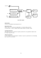


I/O Port
I/O Port A
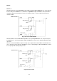
Pin PA0 and PA1 are shared with DDC interface SDA1 and SCL1 When ENDDC bit is “0”, These two pins
becomes I/O port. If PA0OE bit is set, Pin PA0 is an open-drain output. If PA0OE is cleared, Pin PA0 is
an input pin with no internal pull-up resistor. The operation of PA1 is same as PA0. Fig. 2 Shows the
structure of PA0.
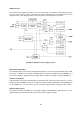
Pin PA2 to PA6 are shared with PWM output. When corresponding EPWMx bit is “0”, the pin is I/O port.
If PAxOE bit is set, it is a push-pull type output. If PAxOE bit is cleared, it is an input pin with internal pull-
up resistor.
Pin PA7 is shared with PWM13 output and clamp pulse output. When both EPWM13 bit and ENCLP bit
are “0”, this pin becomes I/O port. If PA7OE bit is set, it is a push-pull type output. If PA7OE bit is cleared,
it is an input pin with internal pull-up resistor.
49
Fig.2 Structure of PA0 and PA1
Fig.3 Structure of PA2