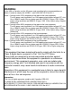
VIDEO COPY PROCESSOR MODEL P93W P93E OPERATION MANUAL SIDE NOR 1:1 SIZE BRT ADJUST BRT CONT FUNC FEED COPY PRINT CONT MULTI SINGLE EXP. MODE EXP. OPEN THIS OPERATION MANUAL IS IMPORTANT TO YOU. PLEASE READ IT BEFORE USING YOUR VIDEO COPY PROCESSOR. VIDEO COPY PROCESSOR This video copy processor complies with the requirements of the EC Directive 89/336/ EEC, 73/23/EEC, 93/42/EEC and 93/68/EEC.
FOR THE MODEL P91DW(UB) ONLY WARNING: In the USA or Canada, use the AC power cord according to the recommendations as below, in order to comply with UL2601-1 and CAN/CSA C22.2 No. 601.1. Case 1. Connect to the 120V receptacle of the room or the host equipment. The AC power cord should be UL or CSA approved and consist of type SJT, size 16 or 18AWG, length 2.5m or shorter cord with IEC320/C13 type, 125V 10A or higher rating connector and NEMA 5-15 type, 125V 10A or higher rating, Hospital Grade plug.
CAUTION: RISK OF ELECTRIC SHOCK DO NOT OPEN. TO REDUCE THE RISK OF ELECTRIC SHOCK,DO NOT REMOVE COVER (OR BACK) NO USER-SERVICEABLE PARTS INSIDE. REFER SERVICING TO QUALIFIED SERVICE PERSONNEL. The lightning flash with arrowhead symbol, within an equilateral triangle, is intended to alert the user to the presence of uninsulated "dangerous voltage" within the product's enclosure that may be of sufficient magnitude to constitute a risk of electric shock.
1 CONTENTS 1 CONTENTS .................................................................. 1 2 PRECAUTIONS ....................................................... 2 - 4 3 UNPACKING ................................................................. 5 4 FEATURES AND FUNCTIONS 5 6 7 8 9 A B C D E F Front Panel ............................................................... 6 Rear Panel ................................................................ 7 INSTALLATION OF PAPER ....................................
2 PRECAUTIONS In the interest of safety, please observe the following precautions: POWER REQUIREMENT This Video Copy Processor is designed for operation on 100-240V AC 50/60Hz. Never connect to any outlet or power supply having a different voltage or frequency. WARNING : THIS APPARATUS MUST BE EARTHED. AVERTISSEMENT : CET APPAREIL DOIT ETRE MIS A LA TERRE. This equipment is classified as class 1, according to the type of protection against electric shock. PROTECTIVE MEASURES IF ABNORMALITIES ARISE, . .
FOR LONG OPERATING LIFE UNSUITABLE MATERIALS FOR THE UNIT Many plastic components are used in the unit. Coat flaking and deformation are likely to occur if the unit is wiped with chemical dusters, benzine, thinner or any other solvent, if rubber or PVC items are left in contact with the unit for extended duration, or if the unit is sprayed with insecticide. CARE OF THE CABINET Unplug and clean with a soft cloth slightly moistened with a mild soap and water solution. Allow to dry completely before operating.
SAFETY TECHNICAL CHECKS Periods: According to the recommendations of the manufacturer of medical device. Scope: a) Visual check Housing, cables, operator controls, readout device ( displays, LED etc.), labels, accessories, instruction manual. b) Function test Performance check acc. instruction manual, also unity and applicability of set and accessory test. c) Electrical check Safety electrical test of the configuration in accordance with EN60601-1.
3 UNPACKING Take the unit out of the box by the following procedures. Make sure to check the contents. 1 Open the top of the box. 3 Take the unit out of the box carefully. • Make sure to keep the unit horizontal. 2 Remove the cushion above the unit. 4 Unwrap the unit. SIZE SIZE MULTI MODE NOR. 1:1 SINGLE EXP. BRT CONT EXP.
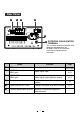
4 FEATURES AND FUNCTIONS Front Panel 1 23 4 5 6 7 8 9 A B C SIDE NOR 1:1 SIZE BRT ADJUST BRT CONT FUNC FEED COPY PRINT CONT D MULTI SINGLE EXP. MODE E 1 2 3 4 5 6 7 8 9 A B C D E EXP. OPEN Function Name Power switch Turns on/off the power. SIZE switch Selects the size of images to print. MODE switch Indicator Indicator (BRT/CONT/EXP.) ADJUST control Reference Page 12 • 31 22 Selects the extended function of the SIZE 23 switch.
Rear Panel F G H I REMOTE ON OFF DIP SW OUT VIDEO IN AC LINE J EQUALIZATION K POTENTIAL TERMINAL DIP SW FUNCTION TABLE 1 2 3 FUNCTION IMP TRAP MEMORY SW-ON SW-OFF NO. 75Ω HIGH ON OFF FIELD FRAME 4 5 6 RESERVED This is used to equalize the potential of the equipment connected to this unit. For details refer to the installation instruction of equipment to be connected. F G H I J K Function Name Reference Page DIP switch Selects special functions.
5 INSTALLATION OF PAPER Paper (High-density paper KP65HM-CE) 3 Pull out the paper end. Moisture, fingerprints or dust on the paper surface may cause a noise at printing or deterioration in print quality. Set the paper by the following procedure to prevent adhesion of fingerprint or dust on the paper surface. • Pull out the first 1520cm (6 in. - 9 in.) of the paper to remove any slack in the roll. 1 Open the door. 4 Close the door. • Switch the lever located on the left side to the “OPEN” position.
When setting the paper, observe the following precautions to prevent paper jam. Do not use defective paper. Do not use bent or wrinkled paper. Adjust the paper position correctly. When the paper is fed out skewed from the print exit, adjust the paper position so that it is fed out straight. Do not allow slack in the paper roll. Set the paper tightly to remove any slack. If the side of the print paper is uneven or the core is sticking out, the amount of paper feeding after printing may vary.
6 EXAMPLE OF CONNECTION / SETTING OF SWITCHES Connecting to various composite video signal equipment such as medical equipment. Composite Video Signal Video signal equipment Television 1 Turn off the power switches of the Video copy processor and the equipment to be connected. 2 Connect the VIDEO input terminal of the Video copy processor to the video output terminal of the connected equipment.
Medical Video Signal 1 Turn off the power switches of the Video copy processor and the equipment to be connected. 2 Connect the VIDEO input terminal of the Video copy processor to the video output terminal of the connected equipment. Rear panel To VIDEO output terminal To VIDEO IN terminal REMOTE ON OFF DIP SW IN OUT VIDEO AC LINE DIP SW FUNCTION TABLE NO.
7 PRINTING Printing Procedure 1 Turn on the power. 3 Cut the printed paper. • Press the “POWER” switch to turn on the power. 2 • Cut the printed paper with the cutter by tearing off the paper in the upper right direction. cutter Print a picture displayed on the screen. • Display a picture to be printed on the monitor screen, and press the PRINT button. When printing finishes, a buzzer tone will be heard.
Use of Remote Control Connect the wired remote control to the remote control terminal on the rear panel. Press the button on the remote control to print pictures. This button functions the same as the PRINT button. When no signal is input, the button is invalid. Rear panel REMOTE ON OFF DIP SW IN OUT VIDEO AC LINE DIP SW FUNCTION TABLE 1 2 3 FUNCTION IMP TRAP MEMORY SW-ON SW-OFF NO.
8 ADJUSTMENT OF PRINT PICTURE Adjustment of Brightness/Contrast You can adjust brightness and contrast of the printed picture while observing the monitor screen. Control panel SIDE NOR BRT 1:1 SIZE ADJUST BRT CONT FUNC FEED COPY CONT MULTI SINGLE EXP. EXP. MODE • For adjustment, use the BRT button " BRT ", CONT button " CONT " and ADJUST control " ADJUST ". 1 Press the buttons to adjust brightness or contrast.
2 Change the setting. ADJUST ADJUST 3 Store the set value. By pressing the PRINT button, the setting value is memorized. The memorized value will not be lost even when the power is turned off. • Turn the control clockwise to increase the value. • Turn the control counterclockwise to decrease the value. The setting value is displayed by the indicator. (example) Setting range is -19 to +19.
9 SETTING FUNCTION MODE Function mode In this mode, the initial setting value of each function can be changed. Each time the FUNC button is pressed, the mode is switched as follows. SIDE NOR 1:1 SIZE BRT ADJUST BRT CONT FUNC FEED COPY PRINT CONT MULTI SINGLE EXP. MODE EXP.
Setting the function mode By turning the ADJUST control, you can change the setting value of each function mode. The set values will not be lost even when the power is turned off. ADJUST ADJUST γ curve setting Indicator Purpose and description • To select the gamma (γ) curve (relation between the density and the brightness of the image) to obtain an optimum density depending on the connected device. Five options are available. • The default setting is 5.
Selection of the second image for the multi image copy printing Indicator Purpose and description • You can select any image from the last 10 printed images for 2multi image printing. • The larger the number displayed by the indicator becomes, the older the selected image is. (Selectable range : 0 to 9) • The image selected in this mode is printed on the left for 2-multi image copy printing. • The selected image is displayed on the monitor. • The selected image is kept until a new image is memorized.
Printing of the setting values Indicator Purpose and description • You can include the setting values of BRT, CONT and GAMMA in the print at the bottom. : The setting values are not printed. : The setting values are printed. , SCAN setting Indicator Purpose and description • You can select underscan or overscan of the print image. : Underscan : Overscan , A A (Underscan) (Overscan) IMAGE setting Indicator , Purpose and description • You can select the print pattern, positive print or negative.
DIRECTION setting Indicator Purpose and description • You can select the print direction. : Printing starts from the bottom of the image. (The image is rotated 180°) : Printing starts from the top of the image. A , A (Normal) (Reverse) SAVING setting Indicator Purpose and description • You can select the amount of paper for preparing a margin of the next print.
PRINT button function setting Indicator , , Purpose and description • You can extend the function of the PRINT button. : Normal function only : The image is copied as many times as the PRINT button is pressed. : The printed images are memorized during printing. Setting of the number of prints Indicator Purpose and description • You can select the number of prints when you press the PRINT button. • The selectable number is to and (continuous printing).
SIZE switch setting The size of the printed image can be selected by the SIZE switch. SIDE NOR 1:1 SIZE Example A SIDE NOR.
MODE switch setting MODE switch works as the extended function of SIZE switch. MULTI SINGLE EXP. MODE Set this switch to SINGLE for normal use. The image is printed in the size specified by the SIZE switch. When selecting MULTI, you can print 2-multi images. • To print a multi image, press the PRINT button twice. • At the first press of the PRINT button, the first image is memorized and the indicator displays .
Print patterns depending on the combination of the settings of the SIZE and MODE switches SIZE SIDE NOR 1:1 A A MULTI EXP. A B SINGLE A MODE A B A 24 Printing is not available. Printing is not available.
User setting This unit can memorize the settings which you adjusted to meet the operating conditions of the connected devices and the print quality conditions as the "user setting". When you change the setting by mistake, you can correct it with a simple operation. Memorizing the user setting 1 The service personnel of this unit memorizes the settings. Contact your dealer. Setting back to the user setting 1 2 3 Turn off the power. While pressing the COPY button, turn on the power.
10 ERROR DISPLAY In case of an error in the unit during operation, you are warned by an alarm tone or the LED indicator. Cause/Error display 1 Overheat Symptom/Remedy [Symptom] • When the head gets overheated, the indicator blinks. In this case, the following buttons function as described below. When overheat occurs during continuous printing, printing starts as soon as the error is solved. COPY button • Each time the COPY button is pressed, the number displayed by .
Cause/Error display 2 No paper Symptom/Remedy [Symptom] • When the paper runs out or the paper is not installed, printing becomes impossible and an alarm tone is heard. In this case, all the buttons become invalid. • If this error occurs while more than one copy is being printed or there are images waiting to be processed, printing is cancelled at the occurrence of the error. [Remedy] Install a new roll of paper according to "5. INSTALLATION OF PAPER" on page 8.
Cause/Error display 4 Door error Symptom/Remedy [Symptom] • When the door opens, an alarm tone is heard. The indicator displays " " for one second. In this case, all the buttons become invalid. • If this error occurs while more than one copy is being printed or there are images waiting to be processed, printing is cancelled at the occurrence of the error. [Remedy] Close the door.
11 DIP SWITCH FUNCTIONS ON OFF DIP SW DIP SW FUNCTION TABLE NO. 1 2 3 FUNCTION IMP TRAP MEMORY SW-ON SW-OFF 75Ω HIGH ON OFF FIELD FRAME 2 3 5 6 RESERVED Functions DIP SWITCH 1 4 IMP (IMPEDANCE) 75Ω / HIGH Set to "75Ω" in normal use. Set to "HIGH" when making branch connection of a monitor or other units to the VIDEO IN connector. TRAP ON / OFF Set to "OFF" in normal use. Set to "ON" when inputting a color signal. ON : The trap circuit is active. OFF : The trap circuit is inactive.
12 STATUS AND MODES LED display Contents of right side LED display Video output Power off Power off Through Stand-by Normal stand-by Through γ-curve set mode (γ-curve) γ-curve No. Through Selection of the memorized image for copy printing Selection of the memorized image for multi copy printing Setting of the horizontal print area Image No. in the memory Image No.
13 USE OF CLEANING PAPER When the thermal head is dirty with dust, etc., white spots or stripes may appear on the print. In this case, clean the thermal head by the following procedure BY USING THE SUPPLIED CLEANING PAPER. 1 4 Turn on the power. Close the door. Press the POWER switch to turn on the power. 2 Close the door without taking out the cleaning paper. Open the door. OPEN Switch the left side lever to the OPEN position. 5 Press the "FEED" button. FEED 3 Insert the cleaning paper.
14 MAINTENANCE Turn off the power for maintenance. Maintenance of Main Unit Wipe off stains of the front panel with a soft cloth. When the panel is heavily stained, wipe of with the cloth moistened with neutral cleanser diluted by water and finish with a dry cloth. Maintenance of Rubber Roller When the rubber roller is dirty with dust, etc., a blank spot may appear on the print. In this case, eliminate the dust on to the rubber roller with a blower or a brush.
15 SPECIFICATIONS Type: Video Copy Processor Model: P93W / P93E Power supply and power consumption: 100-240V AC, 50/60Hz, 1.5 - 0.8A Connection terminal: Video input terminal (BNC contact plug) Video output terminal (BNC contact plug) Resolution: Horizontal 1280 pixels x Vertical 500 lines (Standard) (NTSC) Horizontal 1280 pixels x Vertical 600 lines (Standard) (PAL) Gradation: 256 gradations Printing speed: 3.3 sec (Standard) (NTSC), 3.
MITSUBISHI DIGITAL ELECTRONICS AMERICA, INC. 9351 Jeronimo Road, Irvine, CA 92618 Phone 949-465-6000 Mitsubishi Electric Europe B.V. UK Branch Travellers Lane, Hatfield, Herts. AL10 8XB, England, U.K. Phone (0) 1707 276100 FAX (0) 1707 278755 German Branch Gothaer Strasse 8, 40880 Ratingen ; Postfach 1548, 40835 Ratingen ; Germany Phone (2102) 486-9250 FAX (2102) 486-7320 French Branch 25, Boulevard des Bouvets - 92741 NANTERRE cedex Phone (01) 55.68.55.00 FAX (01) 55.68.57.