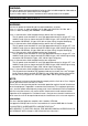
VIDEO COPY PROCESSOR MODEL P91W P91E OPERATION MANUAL BRT CONT PRT-SIZE GAMMA COPY/FEED PRINT OPEN THIS OPERATION MANUAL IS IMPORTANT TO YOU. PLEASE READ IT BEFORE USING YOUR VIDEO COPY PROCESSOR. VIDEO COPY PROCESSOR This video copy processor complies with the requirements of the EC Directive 89/336/ EEC, 73/23/EEC, 93/42/EEC and 93/68/EEC.
WARNING: Use the AC power cord recommended as below and the included composite video cable so as not to interfere with radio and television reception. If you use other cables, it causes interference with radio and television reception. FOR THE MODEL P91W ONLY WARNING: Use the AC power cord according to the recommendations as below, Case 1, 2, 3 and 4; in order to comply with UL2601 and CAN/CSA C22.2 No. 601.1. Case 5; in order to comply with EN60601-1 and EN60950. Case 1.
CAUTION RISK OF ELECTRIC SHOCK DO NOT OPEN CAUTION: TO REDUCE THE RISK OF ELECTRIC SHOCK, DO NOT REMOVE COVER (OR BACK) NO USER-SERVICEABLE PARTS INSIDE REFER SERVICING TO QUALIFIED SERVICE PERSONNEL. The lightning flash with arrowhead symbol, within an equilateral triangle, is intended to alert the user to the presence of uninsulated "dangerous voltage" within the product's enclosure that may be of sufficient magnitude to constitute a risk of electric shock.
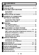
1 CONTENTS 1 CONTENTS .................................................................. 1 2 PRECAUTIONS ....................................................... 2 - 4 3 FEATURES AND FUNCTIONS Front Panel ............................................................... 5 Rear Panel ................................................................ 6 4 INSTALLATION OF PAPER .................................... 7 - 8 5 EXAMPLE OF CONNECTION / SETTING OF SWITCHES Composite Video Signal ..........................
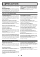
2 PRECAUTIONS In the interest of safety, please observe the following precautions: POWER REQUIREMENT This Video Copy Processor is designed for operation on 120/220-240V AC 50/60Hz in U.S.A and Canada, 220240V AC 50/60Hz in Europe. Never connect to any outlet or power supply having a different voltage or frequency. WARNING : THIS APPARATUS MUST BE EARTHED. AVERTISSEMENT : CET APPAREIL DOIT ETRE MIS A LA TERRE.
FOR LONG OPERATING LIFE UNSUITABLE MATERIALS FOR THE UNIT Many plastic components are used in the back-side. Coat flaking and deformation are likely to occur if the unit is wiped with chemical dusters, benzine, thinner or any other solvent, if rubbers or PVC items are left in contact with the unit for extended duration, or if the unit is sprayed with insecticide. CARE OF THE CABINET Unplug and clean with a soft cloth slightly moistened with a mild soap and water solution.
SAFETY TECHNICAL CHECKS Periods: According to the recommendations of the manufacturer of medical device. Scope: a) Visual check Housing, cables, operator controls, readout device ( displays, LED etc.), labels, accessories, instruction manual. b) Function test Performance check acc. instruction manual, also unity and applicability of set and accessory test. c) Electrical check Safety electrical test of the configuration in accordance with EN60601-1.
3 FEATURES AND FUNCTIONS Front Panel 1 2 BRT A 3 4 CONT 5 PRT-SIZE 6 GAMMA 7 8 COPY/FEED PRINT OPEN 9 Function Name 1 Power switch 2 Brightness buttons 3 Contrast buttons 4 Indicator 5 Print size button 6 Gamma button 7 Copy/Feed button 8 Print button 9 Print exit/Cutter A Lever Turns on/off the power. Press these buttons to select brightness adjustment mode. Press these buttons to select the contrast adjustment mode. Displays standby, functions and error messages.
Rear Panel F CD E 1 2 3 4 5 IMP TRAP GAIN IMAGE AFC 75Ω ON ON NEGA ON HIGH OFF OFF POSI OFF ADJUST H-POSI AFC B 6 7 8 9 10 DIR MEMORY SCAN SAVING PAPER REV FIELD OVER ON SUPER NOR FRAME UNDER OFF HD REMOTE 1 2 3 4 5 6 7 8 9 10 OFF← ON OFF IN OUT VIDEO G AC LINE H I POTENTIAL EQUALIZATION TERMINAL This is used to equalize the potential of the equipment connected to this unit. For details refer to the installation instruction of equipment to be connected.
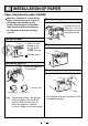
4 INSTALLATION OF PAPER Paper (High-density paper K65HM) Moisture, fingerprints or dust on the paper surface may cause a noise at printing or deterioration in print quality. Set the paper in the following procedure to prevent adhesion of fingerprint or dust on the paper surface. 3 Pull out the paper end. • Pull out the first 15- 20cm (6 in. - 9 in.) of the paper to remove any slack in the roll. 1 Open the door. • Switch the lever 4 Close the door. located on the left side to the “OPEN” position.
When setting the paper, observe the following precautions to prevent paper jam. Do not use defective paper. Do not use the bent or wrinkled paper. Adjust the paper position correctly. When the paper is fed out skewed from the print exit, adjust the paper position so that it is fed out straight. If the side of the print paper is uneven or the core is sticking out, the amount of paper feeding after printing may vary.
5 EXAMPLE OF CONNECTION / SETTING OF SWITCHES Connecting to various composite video signal equipments such as medical equipment. Composite Video Signal Video signal equipment Television 1 Turn off the power switches of the Video copy processor and the equipment to be connected. 2 Connect the VIDEO input terminal of the Video copy processor to the video output terminal of the connecting equipment.
For the functions of the MODE switch, refer to "MODE SWITCH FUNCTIONS" on page 21 - 23. Medical Video Signal 1 Turn off the power switches of the Video copy processor and the equipment to be connected. 2 Connect the VIDEO input terminal of the Video copy processor to the video output terminal of the connecting equipment.
6 PRINTING Printing Procedure 1 Turn on the power. 3 Cut the printed paper. • Press the “POWER” switch to turn on the power. cutter • Cut the printed paper with the cutter by tearing off the paper in the upper right direction. 2 Print a picture displayed on the screen. • Display a picture to be printed on the monitor screen, and press the " PRINT " button. When printing is over, a buzzer tone will be heard.
Use of Remote Control Rear panel 1 2 3 4 5 IMP TRAP GAIN IMAGE AFC 75Ω ON ON NEGA ON HIGH OFF OFF POSI OFF ADJUST H-POSI AFC 6 7 8 9 10 DIR MEMORY SCAN SAVING PAPER REV FIELD OVER ON SUPER NOR FRAME UNDER OFF HD REMOTE ON 1 2 3 4 5 6 7 8 9 10 OFF← Connect the wired remote control to the remote control terminal on the rear panel. Press the remote control button to print pictures. This performs the same function as the "PRINT" button.
7 ADJUSTMENT OF PRINT PICTURE Adjustment of Brightness/Contrast You can adjust brightness and contrast of print while observing the monitor screen. Control panel BRT CONT PRT-SIZE GAMMA COPY/FEED • To adjust pictures, use the bright buttons "}" and "{" of BRT " "}" and "{" of CONT " ", the contrast buttons ". 1 Press the buttons to adjust brightness or contrast. Press the bright buttons "}" and "{" of BRT " " to adjust brightness.
2 Store the set value. PRINT BRT CONT PRT-SIZE GAMMA COPY/FEED A value is stored by pressing "PRINT" button. PRINT OPEN A stored value will not be lost even if the power is turned off. ABC mode (Automatic Brightness Control) ABC mode can be set to adjust the brightness of the print picture. ABC mode is the function that checks and adjusts automatically the brightness of the input signal whenever the "PRINT" button is pressed. Setting ABC mode 1 Turn on the power. 2 Hold down the "PRT-SIZE" button.
Releasing ABC mode Hold down the print size button " " for approx. 3 seconds. A tone is given, LED display changes from to and ABC mode is released. Selection of Gamma (γ) Curve You can select γ-curve by pressing the gamma button " ". Each time the button is pressed, the indicator and γ-curve number is switched. After a γ-curve number has been selected, press any other button to store the γ-curve number.
Selection of Print Size You can select print size by pressing the print-size button " ". Each time the button is pressed, the indicator and print size is switched as follows. After a print size has been selected, press any other button to store the print size. CONT LED display Normal Print size LED display A Large 1.7 Print size PRT-SIZE GAMMA COPY/FEED {" or "} }" of Pressing "{ CONT button when selecting Large 1.5 or Large 1.7, the center position of the print image can be adjusted.
8 SPECIAL FUNCTION Locking the settings You can lock the setting of each button on the front panel (BRT, CONT, PRT-SIZE, GAMMA) . Locking the setting (e.g. brightness) 1 Turn on the power. • Press the "POWER" switch to turn on the power. 2 Lock the setting of the brightness (BRT) • While holding down the "}" or "{" of BRT button, press the "PRINT" button for approx. 3 seconds. A tone is given and the setting of the BRT button is locked.
Printing the set conditions You can print the set conditions of BRT, CONT and GAMMA under the image. 1 Turn on the power. 3 Set to the stand-by status. • Press the "POWER" switch to turn on • While holding down the "}" of BRT button, press the "{" of BRT button for approx. 3 seconds till a "Peep" sounds. " " is displayed on the indicator. the power. BRT CONT PRT-SIZE GAMMA COPY/FEED PRINT OPEN 2 Make a setting to print the set conditions.
9 ERROR DISPLAY When an error in operation occurs it is warned by an audible alarm and a visible error display in the LED indicator. Cause/Error display 1 No paper Symptom/ Remedy [Symptom] • When the paper runs out or the paper is not installed, printing becomes impossible and alarm tone is given. [Remedy] Install brand-new paper according to “4. INSTALLATION OF PAPER” on page 7.
Cause/Error display 4 Door error Symptom/ Remedy [Symptom] • When the door opens, an alarm tone is given. [Remedy] Close the door. Cause/Error display 5 Gear lock error Symptom/ Remedy [Symptom] • When the thermal head does not automatically go up after printing, an alarm tone is given. • " " is displayed in the indicator and all the button functions become invalid. [Remedy] Turn the power off. Then turn it on again.
10 MODE SWITCH FUNCTIONS 1 2 3 4 5 IMP TRAP GAIN IMAGE AFC 75Ω ON ON NEGA ON HIGH OFF OFF POSI OFF 6 7 8 9 10 DIR MEMORY SCAN SAVING PAPER REV FIELD OVER ON SUPER NOR FRAME UNDER OFF HD REMOTE 1 2 3 4 5 6 7 8 9 10 OFF← ON OFF MODE SWITCH (DIP switch) Functions 1 IMP (IMPEDANCE) 75Ω/HIGH Usually set to "75Ω". Set to "HIGH" when making branch connection of a monitor or other units to the VIDEO IN connector. 2 TRAP ON/OFF When this is set to "ON", the color trap circuit functions.
MODE SWITCH (DIP switch) Functions 5 AFC ON/OFF Usually set to "OFF". Set to "ON" when connecting equipment with a poor signal. Picture quality will be improved. 6 DIR (DIRECTION) REV/NOR NOR (NORMAL): A picture is printed in the same direction as the display. REV(REVERSE): A picture is printed reverse to the display (180° turned). This function is invalid when the print size is set to "Side", "Side (small)" or "Large (x1.5 / x1.7)".
MODE SWITCH (DIP switch) 9 SAVING (PAPER SAVING) ON/OFF Functions Set this switch to select the margin size. ON: Printed with narrow margin. OFF: Printed with normal margin.
11 STATUS AND MODES Set state/Mode LED display Point and Left right Power off Stand-by Print state Contents of right side LED display Video output Power off Through Except small size Through Small size for 1st image Through Small size for 2nd image Through Print state Through Copy state - Remained copy number Through Brightness adjustment mode (Bright) - Brightness index Monitor Contrast adjustment mode (Contrast) - Contrast index Monitor γ-curve set mode (γ-curve) - γ-curve
12 USE OF CLEANING PAPER When the thermal head is dirty with dust and perspiration, etc., white spots or stripes may appear on the print. In this case, clean the thermal head in the following procedure BY USING THE SUPPLIED CLEANING PAPER. 1 Turn on the power. 4 Close the door. Press the “POWER” switch to turn on the power. Close the door without taking out the cleaning paper. 2 Open the door. Switch the left side lever to the “OPEN” position. OPEN 5 Press the “COPY/FEED” button.
13 MAINTENANCE Turn off the power for maintenance. Maintenance of Main Unit Wipe off stains of the front panel with a soft cloth. When the panel is heavily stained, wipe off with the cloth moistened with neutral cleanser diluted by water and finish with a dry cloth. Maintenance of Rubber Roller When the rubber roller is dirty with dust, etc., a blank spot may appear on the print. In this case, eliminate the dust on to the rubber roller with a blower or a brush.
14 SPECIFICATIONS Type: Video Copy Processor Model: P91W / P91E Power supply and power consumption: 120V AC, 50/60Hz, 1.2A 220-240V AC, 50/60Hz, 0.7A Connection terminals: Video input terminal (BNC contact plug) Video output terminal (BNC contact plug) Resolution: Horizontal 1022 pixels x Vertical 500 lines (Standard) (NTSC) Horizontal 1022 pixels x Vertical 600 lines (Standard) (PAL) Gradation: 256 gradations Printing speed: 4.7 sec (Standard) (NTSC), 5.
MITSUBISHI ELECTRONICS AMERICA, INC. 5665 PLAZA DRIVE P.O. BOX 6007 CYPRESS, CA 90630-0007, USA Phone (714)220-2500 FAX (714)236-6339 Mitsubishi Electric Europe B.V. UK Branch Travellers Lane, Hatfield, Herts. AL10 8XB, England, U.K. Phone (1) 707 276100 FAX (1) 707 278755 German Branch Gothaer Strasse 8, Postfach 1548, 40880 Ratingen 1, Germany Phone (2102) 4860 FAX (2102) 486-732 French Branch 25, Boulevard des Bouvets - 92741 NANTERRE cedex Phone (01) 55.68.55.00 FAX (01) 55.68.57.