=r.Llllm MITSUBISHI ,mrlELECTRIC Air-Con i PCA-A.GA m |oners INSTALLATION MANUAL For safe and correct use, read this manual the air-conditioner unit. MANUAL i and the outdoor unit installation FO_iNS_ _ manual thoroughly before i installing DE INSTALACION Para un uso correcto y seguro, lea detalladamente antes de instalar la unidad de aire acondicionado.
Contents 1. 2. Safety precautions Installation location 3. Installing the indoor 4. Installing the refrigerant 1. Safety ................................................................................... .................................................................................. unit ........................................................................... piping ................................................................. 2 3 5. 6. Drainage piping work ..........................
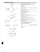
2. Installation location 2.1. Outline dimensions (Indoor unit) (Fig. 2=1) w Select a proper position allowing the following clearances for installation and mainte- nance. (mm) (inch) A24, A30 Models W 1310 61-9/16 D 680 26-7/32 m 221 8-9/32 _ ® @ ® Min. 270 Min. 300 Min. 500 Max. 250 Min, 10-5/8 Min,11-13/1( Min, 19-11/1( Max,9-13/16 A36, A42 1310 51-9/16 680 26-7/32 281 10-5/8 Min. 270 Min. 300 Min. 500 Max. 250 Min, 10-5/8 Min,11-13/1( Min, 19-11/1( Max,9-13/16 2.2.
3. Installing the indoor unit 3.2.5. indoor 1. Install unit preparation the suspending Predetermine bolts. the length from (Fig. 3-4) (Procure the W3/8 or M 10 bolts the ceiling ((j) within 100 ram, locally.) 3-59/64 inch). (A) Ceiling surface _) Suspending bolt © Suspending bracket Fig. 3=4 2. Remove Slide (inch) the intake the intake holding knobs (at two locations) backward to open the intake grille. 3. Remove I grille. grille Remove the side panel.
4. Installing the refrigerant piping 4.1. Precautions 4.1.1. • For devices Use ester applied • that oil, ether to the flared the specified clean phosphorus, refrigerant in the and pounds, R410A table do not oxidants, refrigerant oil (small amount) as the refrigeration oil sections. Use Cl 220 copper to connect use oil, alkylbenzene for copper pipes. to the Use below. contain any debris, or dust.
5, Drainage piping work ®, 5.1. Preparation for left side tubing installation (Fig, 5=1) _) Drain pan - For left side tubing, (_) Plug • Install the • After be sure to insert drain tubing as it slopes completion of work, check the rubber continuously that correct plug into the right drain port. downward. drain is available from the outflow port of the drain tubing. Fig. 5=1 5.2. installing procedures (Fig. 5=2) © 1. Attach the joint socket vinym chloride 2. Fasten .® 3.
6, Electrical work 6.1.1. indoor The following unit power connection The outdoor unit power supp|ied patterns from outdoor unit (A=control app|ication) are available. suppmy patterns vary on models. @ Outdoor unit power supply © (_) @ (_) Wiring circuit breaker or isolating switch [-7 I _ Outdoor unit I I I i @ Indoor unit/outdoor unit connecting cords _) Remote controller !_! (#) indoor unit _sl_l _lnd .....
6. Electrical work ® (inch) ® 6,2.1, i ......................... -_.......................... i,.__ _ I,-_! i ' 6.2. Remote _,i--i _' ' ! ® I I I L Fig. 6=2 ® B-I. B-2. / / / controller For wired remote controller 1) Installing procedures (1) Select an installing position for the remote controller. (Fig. 6-2) The temperature sensors are located on both remote controller and indoor unit.
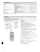
6. Electrical work 6.3. Function settings 6.3.1 Function setting on the unit (Selecting the unit functions) 1) For wired remote controller (Fig. 6-8) Changing the power voltage setting • Be sure to change the power voltage setting depending on the voltage used. ® Go to the function setting mode. Switch OFF the remote controller. (_ Mode number _[_ Setting number _) Refrigerant address @ Unit number Press the _) and ® buttons simultaneously and hold them for at least 2 seconds.
6. Electrical Select unit numbers work 01 to 03 or all units (AL [wired remote controller]/07 Mode Settings Filter sign 100 Hr 2500 Hr [wireless remote controller]) Mode no. Setting 07 Standard No.
7. Test run 7.3. Self=check 7.3.1. (j) Wired remote controller (Fig. 7-3) Turn on the power. Press the [CHECK] Set refrigerant (4) Press button address the [ON/OFF] twice. with button [TEMP] button if system control is used. to stop the self-check. _A_CHECK button _B.bRefrigerant address (C)TEMR button @ IC: OC: Indoor unit Outdoor unit (_ Check code (_ Unit address 7.3.2. (j) Wireless (Start this operation _A__ 3_ While button. ® Fig.
7. Test run [Output pattern Wireless B] Errors remote detected by unit other Wired controller than indoor unit (outdoor unit, etc.
8. Easy maintenance Display example (Comp discharge function temperature function only for A-control] 147°F) (1) Press button mode. for three seconds to activatethethe maintenance (2) Press the TEMP. [This By using the maintenance mode, you can display many types of maintenance data on the remote controller such as the heat exchanger temperature and compressor current consumption for the indoor and outdoor units. This function can be used whether the air conditioner is operating or not.
This product is designed commercial Please and intended be sure to put the contact this manual for use in the residential, and light-industrial before environment. address/telephone handing number on it to the customer. ,,_ MITSUBISNI ELECTRIC CORPORATION HEAD BG79U827H02-A OFFICE.':; TOKYO BLDG.