
Installation guide


5, Drainage piping work
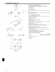
®, 5.1. Preparation for leftside tubing installation (Fig, 5=1)
_) Drain pan - For left side tubing, be sure to insert the rubber plug into the right drain port.
(_) Plug • Install the drain tubing as it slopes continuously downward.
• After completion of work, check that correct drain is available from the outflow port
of the drain tubing.
©
Drain pan
_) Drain tubing (VP2O)
@_ Socket cover (6_
(_ Joint socket (_)
Drain tubing cover (_)
Fig. 5=1
Fig. 5=2
®
Fig. 5=3
.® 3.®
5.2. installing procedures (Fig. 5=2)
1. Attach the joint socket _ supplied with the unit to the drain port on the unit with a
vinym chloride adhesive.
2. Fasten the socket cover (_ supplied with the unit to the joint socket (_.
3. Attach a PVC pipe (O.D. e26 mm, 1-1/32 inch) to the joint socket _ with a vinyl
chloride adhesive.
4. Wrap the drain tubing cover (_) supplied with the unit. (Seam taping)
(_ Drain tubing sensor
5.3. Drain check (Fig. 5-3)
1. Fill the drain pan with water of about 1 L, 1/4 gal from the tubing sensor access
port.
2. Check the drainage.
3. After checking for correct drainage, repmace the tubing sensor access port cover.
6, Electrical work
/ \\
J \
®
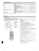
6.1. Electric wiring (Fig. 6=1)
Wiring procedures
1. Remove the (two) tapping screws then remove the electric part cover.
2. Connect the electric wires securely to the corresponding terminals.
3. Replace the removed parts.
4. Tie the emectric wires with the toccatawiring clamp mocated in the right side of the
junction box.
Cover
Set screws
(_) Beam
(_ Wiring clamp
_E_Power supply board
(_ Control board
_') Wire service entrance
(_ Terminal block for indoor and outdoor units connection
Terminal block for remote controller
Grounding cable connector
I
i
Fig. 6=1
6