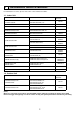
SW1 (MODEL SELECTION) [LEGEND] SYMBOL I.B CN2L CN32 CN41 CN51 FUSE LED1 LED2 LED3 SW1 SW2 SWE X1 DCL DP FS MF MV NAME INDOOR CONTROLLER BOARD CONNECTOR (LOSSNAY) CONNECTOR (REMOTE SWITCH) CONNECTOR (HA TERMINAL-A) CONNECTOR (CENTRALLY CONTROL) FUSE (T6.3AL250V) POWER SUPPLY (I.B) POWER SUPPLY (R.PLA-RP35AA [LEGEND] SYMBOL P.B I.B FUSE ZNR BCR CN2L CN32 CN41 CN51 LED1 LED2 LED3 X1 X4 SW1 SW2 SWE C PLA-RP50AA NAME INDOOR POWER BOARD INDOOR CONTROLLER BOARD FUSE(T6.3AL250V) VARISTOR FAN CONTROL ELEMENT CONNECTOR(LOSSNAY) CONNECTOR(REMOTE SWITCH) CONNECTOR(HA TERMINAL-A) CONNECTOR(CENTRALLY CONTROL) POWER SUPPLY(I.B) POWER SUPPLY(I.
PCA-RP50KA PCA-RP60KA PCA-RP71KA [ LEGEND] SYMBOL I.B CN2L CN32 CN41 CN51 FUSE LED1 LED2 LED3 SW1 SW2 SWE X1 R.B DCL MF MV NAME INDOOR CONTROLLER BOARD CONNECTOR (LOSSNAY) CONNECTOR (REMOTE SWITCH) CONNECTOR (HA TERMINAL-A) CONNECTOR (CENTRALLY CONTROL) FUSE (T6.3AL250V) POWER SUPPLY (I.B) POWER SUPPLY (R.
PCA-RP50GA NAME INDOOR POWER BOARD INDOOR CONTROLLER BOARD FUSE (T6.3AL250V) VARISTOR CONNECTOR(LOSSNAY) CONNECTOR(REMOTE SWITCH) CONNECTOR(HA TERMINAL-A) CONNECTOR(CENTRALLY CONTROL) SWITCH (MODEL SELECTION) See Table 1. SWITCH (CAPACITY CODE) See Table 2. SWITCH(EMERGENCY OPERATION) RELAY(DRAIN PUMP) RELAY(FAN MOTOR) FAN CONTROL ELEMENT POWER SUPPLY(I.B) POWER SUPPLY(R.B) TRANSMISSION(INDOOR-OUTDOOR) CAPACITOR(FAN MOTOR) PCA-RP60GA SYMBOL MF MV DP DS TB4 TB5,TB6 TH1 TH2 TH5 R.B P.
t° 45 TH1 SYMBOL I.B. CN2A CN2L CN32 CN41 CN51 CN90 CN105 LED1 LED2 LED3 1 2 FS *1 1 2 3 4 CN4F CNXB2 (Red) 1 CN2L 23 4 5 CN51 OFF ON LED2 1 2 CNXC2 SWE LED1 4 3 2 1 CNXA2 (Blue) CN22 2 (Blue) 1 (Black) CN2A (Red) CN105 NAME SYMBOL NAME I.B.
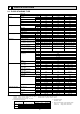
PEAD-RP35EA2 PEAD-RP50EA [LEGEND] NAME SYMBOL I.B. INDOOR CONTROLLER BOARD FUSE FUSE(T6.3AL250V) ZNR VARISTOR CN2L CONNECTOR(LOSSNAY) CN24 CONNECTOR(HEATER) CN32 CONNECTOR(REMOTE SWITCH) CN41 CONNECTOR(HA TERMINAL-A) CN51 CONNECTOR(CENTRALLY CONTROL) CN90 CONNECTOR(WIRELESS) LED1 POWER SUPPLY(I.B.) LED2 POWER SUPPLY(REMOTE CONTROLLER) LED3 TRANSMISSION(INDOOR•OUTDOOR) SW1 SWITCH(MODEL SELECTION) SYMBOL SW2 SWE X1 X4 X5 X6 P.B.
PEAD-RP60GA PEAD-RP71GA [LEGEND] NAME NAME SYMBOL SYMBOL I.B. INDOOR CONTROLLER BOARD SW1 SWITCH(MODEL SELECTION) FUSE FUSE(T6.3AL250V) SW2 SWITCH(CAPACITY CODE) ZNR VARISTOR SWE SWITCH(EMERGENCY OPERATION) CN2L CONNECTOR(LOSSNAY) X1 RELAY(DRAIN PUMP) X4 RELAY(FAN MOTOR) CN24 CONNECTOR(HEATER) CN32 CONNECTOR(REMOTE SWITCH) X5 RELAY(FAN MOTOR) CN41 CONNECTOR(HA TERMINAL-A) X6 RELAY(FAN MOTOR) CN51 CONNECTOR(CENTRALLY CONTROL) P.B.
PEA-RP71EA [LEGEND] SYMBOL SYMBOL NAME P.B INDOOR POWER BOARD I.B SW1 I.B INDOOR CONTROLLER BOARD SW2 FUSE FUSE(T6.3AL250V) SWE ZNR VARISTOR X4 CN2L CONNECTOR(LOSSNAY) X5 CN32 CONNECTOR(REMOTE SWITCH)) X6 CN41 CONNECTOR(HA TERMINAL-A) R.B CN51 CONNECTOR(CENTRALLY CONTROL) TB6 LED1 POWER SUPPLY(I.B) C LED2 POWER SUPPLY(R.
NOTES:1. About the indoor side electric wiring, refer to the indoor unit electric wiring diagram for servicing. 2. Use copper conductors only. (For field wiring) 3. Symbols below indicate.
NOTES:1. About the indoor side electric wiring, refer to the indoor unit electric wiring diagram for servicing. 2. Use copper conductors only. (For field wiring) 3. Symbols below indicate.
3~ MC U BLK WHT RED 1 3 SYMBOL CT C61,62,63 DB61,DB65 DSA F61 F701,F801,F901 HC930,IPM IC802 L61 L62 W MS V RED LDW LDV LDU U V P N IPM W R825 TR821 1 R61 3 5 MF MS 3~ CN932 3 5 F901 F801 R937A 1 T801 1 RT64 2 1 CN642 HC930 R937B IC802 RT68 CN644 RT65 RT61 RT62 CN641 4 1 LEV M 6 CN724 6 CT LD61 U F701 LD63 BRN U 1 CN721 LD-E1 2 F61 LD62 U LD-S L62 DSA PTC65 PTC64 X64 X63 21S4 BRN BLU RED GRN/YLW BLK S1 S3 S2 TB2 L N TB1 230V~ 1
SYMBOL CB1~3 CT1, 2 CT61 F64 F801 F911 HC930 HPS IPM L NAME SMOOTHING CAPACITOR CURRENT TRANSFORMER CURRENT TRANSFORMER FUSE (T2AL 250V) FUSE (T3.15AL 250V) FUSE (T1AL 250V) INTELLIGENT POWER MODULE HIGH PRESSURE SWITCH INTELLIGENT POWER MODULE REACTOR SYMBOL LEV MC MF NF NR64 PFC RS1~4 RT61 RT62 RT64 NAME EXPANSION VALVE COMPRESSOR FAN MOTOR NOISE FILTER VARISTOR POWER FACTOR CONTROLLER RESISTOR DEFROST THERMISTOR DISCHARGE TEMP. THERMISTOR FIN TEMP.
PE NOISE FILTER P.C.BOARD GRN/YLW N S3 RED BLU WHT GRN LDE1 CT61 1 2 RED SYMBOL MC MF NF NR64 PFC R64A,B R937A, B RS1~4 RT61 RT62 RT64 RT61 RT62 CN661 1 2 3 4 RED BLK BLK BLK 4 YLW 1 RT68 7 8 LEV 6 CN795 5 6 7 CN702 3 2 S R CN4 1 2 RS2 RS1 T801 1 3 RS3 LD1 RS4 R937B R937A LD2 CB2 CT1 U U CN932 RED WHT BLK GRN MF POWER RT64 BOARD BLK WHT MC W RED V GRY PNK ORN BLU YLW LD9 IPM V CT2 W NOTES: 1.
5 REFRIGERANT SYSTEM DIAGRAM 5-1. INDOOR UNIT MFZ-KA25VA MFZ-KA35VA MFZ-KA50VA Unit : mm Refrigerant pipe :9.52 (MFZ-KA25/35VA) Refrigerant pipe :12.7 (MFZ-KA50VA) (with heat insulator) Indoor coil thermistor RT12 (main) Distributor Indoor heat exchanger Flared connection Indoor coil thermistor RT12, RT14, RT15 (main) RT13 (sub) Refrigerant flow in cooling Refrigerant flow in heating Room temperature thermistor RT11 Flared connection Refrigerant pipe :6.
5-2. OUTDOOR UNIT SUZ-KA25VA SUZ-KA25VAH Unit:mm Refrigerant pipe ø9.52 (with heat insulator) 4-way valve Muffler Stop valve (with service port) Discharge temperature thermistor RT62 Flared connection Outdoor heat exchanger Muffler Outdoor heat exchanger temperature thermistor RT68 Ambient temperature thermistor RT65 Compressor Defrost thermistor RT61 Strainer #100 Flared connection Refrigerant pipe ø6.35 (with heat insulator) SUZ-KA35VA Capillary tube ø3.0×ø2.0×240 LEV R.V.
SUZ-KA50VA Unit:mm Muffler 4-way valve #100 Refrigerant pipe ø12.7 (with heat insulator) Stop valve (with service port) Flared connection Discharge temperature thermistor RT62 Defrost thermistor RT61 Outdoor heat exchanger Ambient temperature thermistor RT65 Compressor Outdoor heat exchanger temperature thermistor RT68 Flared connection LEV Receiver Refrigerant pipe ø6.35 (with heat insulator) Stop valve (with strainer) Strainer #100 R.V. coil heating ON cooling OFF Capillary tube ø3.6×ø2.
SUZ-KA71VA Unit:mm Refrigerant pipe :15.88 (with heat insulator) Capillary tube :1.8×:0.6×1000 Oil separator High-pressure 4-way valve switch Stop valve (with service port) Strainer #100 Defrost thermistor RT61 Discharge temperature thermistor RT62 Flared connection Compressor Flared connection Strainer Receiver #100 Stop valve Refrigerant pipe :9.52 (with heat insulator) LEV Capillary tube :3.6×:2.
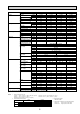
6 PERFORMANCE CURVES FOR THE COMBINATION OF OUTDOOR UNIT SUZ-KA25VA(H) Cooling capacity Capacity correction factors 1.5 Indoor intake air Wet-bulb temperature( ) 1.4 1.3 1.2 26 1.1 24 1.0 22 20 18 0.9 0.8 0.7 0.6 -10 -5 0 5 10 15 20 25 30 35 40 45 Outdoor intake air Dry-bulb temperature( ) Total input (cooling) 1.5 Indoor intake air Wet-bulb temperature( ) Input correction factors 1.4 1.3 1.2 26 22 20 18 24 1.1 1.0 0.9 0.8 0.7 0.
FOR THE COMBINATION OF OUTDOOR UNIT SUZ-KA35VA(H) Cooling capacity Capacity correction factors 1.5 Indoor intake air Wet-bulb temperature( ) 1.4 1.3 26 1.2 1.1 24 1.0 22 20 18 0.9 0.8 0.7 0.6 -10 -5 0 5 10 15 20 25 30 35 40 45 Outdoor intake air Dry-bulb temperature( ) Total input (cooling) 1.5 Indoor intake air Wet-bulb temperature( ) 1.4 Input correction factors 1.3 1.2 26 22 20 18 24 1.1 1.0 0.9 0.8 0.7 0.
FOR THE COMBINATION OF OUTDOOR UNIT SUZ-KA50/60/71VA Cooling capacity 1.5 Indoor intake air Wet-bulb temperature( ) Capacity correction factors 1.4 1.3 1.2 26 1.1 24 1.0 22 20 18 0.9 0.8 0.7 0.6 -15 -10 -5 0 5 10 15 20 25 30 35 40 45 Outdoor intake air Dry-bulb temperature( ) Total input (cooling) 1.3 Indoor intake air Wet-bulb temperature( ) 1.2 22 20 18 24 26 Input correction factors 1.1 1.0 0.9 0.8 0.7 0.6 0.5 0.
Heating capacity Capacity correction factors 1.3 15 20 26 1.2 1.1 Indoor intake air Dry-bulb temperature( ) 1.0 0.9 0.8 0.7 0.6 -10 -5 0 5 10 15 Outdoor intake air Wet-bulb temperature ( ) Total input (heating) 1.3 Input correction factors 1.2 1.1 26 20 15 Indoor intake air Dry-bulb temperature( ) 1.0 0.9 0.8 0.7 0.6 -10 -5 0 5 10 Outdoor intake air Wet-bulb temperature ( ) NOTE: The above curves are for the heating operation without any frost.
7 APPLICABLE EXTENSION PIPE FOR EACH MODEL SUZ-KA25VA SUZ-KA25VAH SUZ-KA35VA SUZ-KA35VAH MAX. REFRIGERANT PIPING LENGTH Models Refrigerant piping Max. length : m A Gas Liquid 20 9.52 6.35 SUZ-KA25VA SUZ-KA35VA SUZ-KA25VAH SUZ-KA35VHA Piping size O.D : mm MAX. HEIGHT DIFFERENCE Indoor unit + Max. Height difference 12m Refrigerant Piping Max. length A Outdoor unit + Height difference should be within 12m regardless of which unit, indoor or outdoor position is high.
SUZ-KA50VA SUZ-KA60VA SUZ-KA71VA MAX. REFRIGERANT PIPING LENGTH Models Refrigerant piping Max. length : m A Piping size O.D : mm Gas SUZ-KA50VA Liquid 12.7 6.35 SUZ-KA60VA 30 15.88 SUZ-KA71VA 9.52 MAX. HEIGHT DIFFERENCE Indoor unit + Max. Height difference 30m Refrigerant Piping Max. length A Outdoor unit + Height difference should be within 30m regardless of which unit, indoor or outdoor position is high.
8 AIR FLOW DATA 8-1. OUTLET AIR SPEED AND COVERAGE RANGE Air flow Air speed Coverage range Air flow Air speed Coverage range Air flow Air speed Coverage range Air flow Air speed Coverage range Air flow Air speed Coverage range m³/min. MFZ-KA25VA MFZ-KA35VA MFZ-KA50VA 8.7 9.1 10.7 m/sec. 1.8 1.9 2.2 m 5.1 5.3 6.2 SLZ-KA25VA SLZ-KA25VAL SLZ-KA35VA SLZ-KA35VAL SLZ-KA50VA SLZ-KA50VAL m³/min. 10 11 11 m/sec. 3.4 3.7 3.7 m 3.7 4.1 4.
8-2. SLZ-KA•VA SLZ-KA•VAL 8-2-1. Fresh air intake (Location for installation) At the time of installation, use the duct holes (cut out) located at the positions shown in following diagram, as and when required. Fresh air intake Detail drawing of fresh air intake 25 :100 :73.4 Cut out hole 0° 12 12 0° 118 3-:2.8 hole Burring hole Ceiling surface Refrigerant pipe Electrical Box Drain pipe 8-2-2.
8-3.
SEZ-KD35VA(L) SEZ-KD35VA(L) (External static pressure 5Pa) 220-240V 50/60Hz (External static pressure 15Pa) 220-240V 50/60Hz 40 50 40 External static pressure (Pa) External static pressure (Pa) 30 Limit 20 High Limit 30 High 20 Middle Rated point 10 Middle 10 Low Rated point Low 0 6 7 8 9 10 Airflow rate(m3/min) 11 SEZ-KD35VA(L) 6 7 8 9 10 Airflow rate(m3/min) 11 12 SEZ-KD35VA(L) (External static pressure 35Pa) 220-240V 50/60Hz (External static pressure 50Pa) 220-240V 50/60H
SEZ-KD50VA(L) SEZ-KD50VA(L) (External static pressure 5Pa) 220-240V 50/60Hz (External static pressure 15Pa) 220-240V 50/60Hz 50 40 Limit Limit 40 External static pressure (Pa) External static pressure (Pa) 30 20 High Middle 30 High 20 Middle Rated point Low 10 10 Low Rated point 0 0 8 9 10 11 12 13 Airflow rate(m3/min) 14 15 8 16 SEZ-KD50VA(L) 9 10 11 12 13 Airflow rate(m3/min) 14 15 16 SEZ-KD50VA(L) (External static pressure 35Pa) 220-240V 50/60Hz (External static pressu
SEZ-KD60VA(L) SEZ-KD60VA(L) (External static pressure 5Pa) 220-240V 50/60Hz (External static pressure 15Pa) 220-240V 50/60Hz 40 50 Limit Limit 40 External static pressure (Pa) External static pressure (Pa) 30 20 High Middle 10 High 30 Middle 20 Low Rated point 10 Low Rated point 0 0 9 10 11 12 13 14 15 Airflow rate(m3/min) 16 17 18 19 SEZ-KD60VA(L) 9 10 11 12 13 14 15 Airflow rate(m3/min) 17 18 19 SEZ-KD60VA(L) (External static pressure 35Pa) 220-240V 50/60Hz (External
SEZ-KD71VA(L) SEZ-KD71VA(L) (External static pressure 5Pa) 220-240V 50/60Hz (External static pressure 15Pa) 220-240V 50/60Hz 40 50 40 External static pressure (Pa) External static pressure (Pa) 30 20 Limit 30 Limit 20 High Rated point 10 High 10 Middle Middle Rated point Low Low 0 0 11 12 13 14 15 16 17 Airflow rate(m3/min) 18 19 20 11 21 SEZ-KD71VA(L) 13 14 15 16 17 Airflow rate(m3/min) 18 19 20 21 SEZ-KD71VA(L) (External static pressure 35Pa) 220-240V 50/60Hz (Extern
8-4. SEZ-KA•VA INDOOR FAN PERFORMANCE AND CORRECTED AIR FLOW SEZ-KA35VA Corrected Air flow 1.1 Correction factor Fan Performance Recommended range 60 20 0 1.0 0.9 0.8 1.3 40 Correction factor External static pressure(Pa) (1Pa = 0.1mmAq) 80 5 7 10 15 20 25 Air flow (*/7) Capacity Input Cooling 5 10 15 20 25 10 15 20 25 Air flow (*/7) Heating 1.2 1.1 1.0 0.9 0.8 5 Air flow (*/7) SEZ-KA50VA Corrected Airflow Fan Performance Correction factor 1.1 Recommended range 60 1.0 0.
INDOOR FAN PERFORMANCE AND CORRECTED AIR FLOW SEZ-KA60VA Corrected Air flow 1.1 Correction factor Fan Performance Recommended range 60 40 20 0 1.0 0.9 0.8 1.3 Correction factor External static pressure(Pa) (1Pa = 0.1mmAq) 80 5 10 15 20 25 Air flow (*/7) Capacity Input Cooling 10 15 20 25 30 15 20 25 30 Air flow (*/7) Heating 1.2 1.1 1.0 0.9 10 Air flow (*/7) SEZ-KA71VA Corrected Air flow 1.1 Correction factor Fan Performance Recommended range 60 40 20 0 1.0 0.9 0.8 1.
8-5. PLA-RP·BA 8-5-1 FRESH AIR INTAKE AND BRANCH DUCT 1. Branch duct hole and fresh air intake hole (Fig. 1) At the time of i nstallation, use the duct holes ( cut out) located at the positions shown in Fig.1, as and when required. • A fresh air intake hole for the optional multi function casement can also be made. Note: The figure marked with * in the drawing represent the dimensions of the main unit excluding those of the optional multi function casement.
3.
4. Change of outlet numbers Indoor unit [The optional air outlet is necessary.] To change the air outlet number to 3-, or 2-way outlet, the outlet number should be closed with the operational air outlet shutter. (When the air outlets are closed, close the vane by removing the vane connector.) Outlet concave portion Button Vane motor Up/down vanes Connector Air outlet shutter plate (Option) Vane motor Connector Button 5.
PLA-RP71BA(2) 4-way airflow (horizontal vane) Round duct 4-way airflow (horizontal vane) Rectangular duct 30 Duct Static pressure [Pa] Static pressure [Pa] 30 20 10 High Duct 20 10 High Low Low 0 0 0 2 4 6 Airflow rate [m3/min] 0 8 3-way airflow (horizontal vane) Round duct 2 80 70 70 Duct Duct 60 Close Static pressure [Pa] Static pressure [Pa] 60 50 40 30 Close 50 40 30 High 20 20 High Low 10 0 Low 10 2 4 6 8 Airflow rate [m3/min] 0 10 2-way airflow (horizontal va
8-6. PLA-RP·AA 8-6-1. Fresh air intake amount 1. Adjusting the width of the air outlets ● Change of outlet numbers [The optional air outlet shutter is necessary.] To change the air outlet numbers to 3-, or 2-way outlet, the outlets should be closed with the optional air outlet shutter. When the air outlets are closed, close the vane by removing the vane connector. ● For the portion to be cut (V-shaped groove), see the figure below (as seen from the rear of the panel). 2.
3.
Branch duct air flow rate/static pressure characteristics PLA-RP35AA 4-way air flow (horizontal vane) Rectangular duct 4-way air flow (horizontal vane) Round duct 3-way air flow (horizontal vane) Rectangular duct 3-way air flow (horizontal vane) Round duct 2-way air flow (horizontal vane) Rectangular duct 2-way air flow (horizontal vane) Round duct 79
PLA-RP50AA PLA-RP60AA 4-way air flow (horizontal vane) Rectangular duct 4-way air flow (horizontal vane) Round duct 3-way air flow (horizontal vane) Rectangular duct 3-way air flow (horizontal vane) Round duct 2-way air flow (horizontal vane) Rectangular duct 2-way air flow (horizontal vane) Round duct 80
PLA-RP71AA 4-way air flow (horizontal vane) Round duct 30 Static pressure [Pa] Static pressure [Pa] 4-way air flow (horizontal vane) Rectangular duct 20 High 10 Low 0 1 2 3 4 5 6 30 20 High 10 Low 0 1 2 3 Air flow rate [m /min] 6 3-way air flow (horizontal vane) Round duct 60 60 Static pressure [Pa] 50 40 High 30 20 Low 10 0 1 2 3 4 5 6 7 8 50 40 High 30 20 Low 10 0 9 1 2 3 4 Air flow rate [m /min] 2-way air flow (horizontal vane) Rectangular duct 90 90 80
8-7. PCA-RP·KA 8-7-1.
8-8. PEAD-RP·JA(L), EA, EA2, GA 8-8-1.
PEAD-RP50JA(L) (External static pressure 100Pa) 220-240V 50Hz PEAD-RP50JA(L) (External static pressure 35Pa) 220-240V 50Hz 130 70 120 110 60 50 High 40 Rated point Middle 30 Low 20 Rated point Limit 100 External static pressure (Pa) External static pressure (Pa) Limit 90 High 80 70 Middle 60 50 Low 40 30 20 10 10 0 9 14 0 19 9 14 19 Airflow rate(m3/min) Airflow rate(m3/min) PEAD-RP50JA(L) (External static pressure 50Pa) 220-240V 50Hz PEAD-RP50JA(L) (External static pressure
PEAD-RP60JA(L) (External static pressure 100Pa) 220-240V 50Hz PEAD-RP60JA(L) (External static pressure 35Pa) 220-240V 50Hz 120 60 110 50 Rated point 100 External static pressure (Pa) External static pressure (Pa) Limit 40 Rated point 30 High 20 Middle 90 Limit High 80 70 Middle 60 50 Low 40 30 Low 10 20 10 0 10 15 20 25 0 10 30 15 Airflow rate(m3/min) 20 PEAD-RP60JA(L) (External static pressure 50Pa) 220-240V 50Hz 170 160 Rated point 150 Limit 140 Rated point 50 External st
PEAD-RP71JA(L) (External static pressure 100Pa) 220-240V 50Hz PEAD-RP71JA(L) (External static pressure 35Pa) 220-240V 50Hz 70 130 120 60 High 110 Rated point 50 External static pressure (Pa) External static pressure (Pa) 100 Limit High 40 Rated point 30 Middle 20 Low Limit 90 Middle 80 70 60 Low 50 40 30 10 20 10 0 10 15 20 25 0 30 10 15 Airflow rate(m3/min) 20 25 30 Airflow rate(m3/min) PEAD-RP71JA(L) (External static pressure 50Pa) 220-240V 50Hz PEAD-RP71JA(L) (External
8-8-2. Fan performance and corrected air flow PEAD-RP35EA2 PEAD-RP50EA Fan Performance <30Pa> Corrected Air Flow 120 100 Correction factor External static pressure (Pa) (1Pa 0.1mmAq) 140 80 60 40 20 6 8 Cooling 1.0 0.9 0.8 8 10 10 12 14 16 18 20 AirFlow (CMM) Fan Performance <70Pa> 160 12 14 16 18 Airflow (CMM) 20 22 12 14 16 18 Airflow (CMM) 20 22 Heating 1.3 140 Correction factor External static pressure (Pa) (1Pa 0.1mmAq) 1.1 Capacity input 120 100 80 60 40 1.2 1.1 1.0 0.9 0.
PEAD-RP71EA Fan performance <70Pa> Fan performance <130Pa> Recommended range External static pressure (Pa) (1Pa = 0.1mmAq) External static pressure (Pa) (1Pa = 0.1mmAq) Recommended range 200 180 160 140 Hi Lo 120 100 80 60 40 20 180 160 140 120 80 60 40 20 12 16 20 24 28 32 12 16 20 24 28 32 Air flow (C MM) A ir f low ( C MM) Corrected Air Flow Capacity Input Cooling Heating 1.3 1.2 Correction factor 1.1 Correction factor Hi Lo 100 1.0 0.9 0.8 12 16 20 24 28 1.1 1.0 0.
PEAD-RP71GA 8-9. PEA-RP·EA 8-9-1. Fan performance and corrected airflow PEA-RP71EA Corrected Airflow 1.05 Correction factor Fan Performance Recommended range Hi 150 1.0 0.95 0.9 1.2 100 50 0 15 17 20 17 20 25 30 25 30 Airflow (CMM) Lo Correction factor External static pressure(Pa) (1Pa = 0.1mmAq) 200 25 30 35 Airflow (CMM) Heating 1.15 1.1 1.05 1.0 0.
NOISE CRITERION CURVES 9 MFZ-KA25VA MFZ-KA35VA Super High SPL(dB(A)) COOLING 37 HEATING 37 Super High OCTAVE BAND SOUND PRESSURE LEVEL, dB re 0.
<50Hz> SLZ-KA25VAL SLZ-KA25VA NOTCH SPL(dB) High 37 Medium 31 Low 28 LINE NOTCH SPL(dB) High 38 Medium 33 Low 29 LINE 90 80 70 NC-70 60 NC-60 50 NC-50 40 NC-40 30 NC-30 APPROXIMATE THRESHOLD OF HEARING FOR CONTINUOUS NOISE 20 63 125 250 NC-20 500 1000 2000 4000 OCTAVE BAND SOUND PRESSURE LEVEL, dB (0 dB = 0.0002 bar) OCTAVE BAND SOUND PRESSURE LEVEL, dB (0 dB = 0.
NOISE CRITERION CURVES SEZ-KD25VA(L) NOTCH External static pressure: 5Pa High Middle Low SPL(dB) 29 25 22 LINE SEZ-KD25VA(L) External static pressure: 15Pa 80 70 NC-70 60 NC-60 50 NC-50 40 NC-40 30 NC-30 20 10 APPROXIMATE THRESHOLD OF HEARING FOR CONTINUOUS NOISE 63 NC-20 125 250 500 1000 2000 4000 80 70 60 NC-60 50 NC-50 40 NC-40 30 NC-30 20 10 8000 NC-70 APPROXIMATE THRESHOLD OF HEARING FOR CONTINUOUS NOISE 63 SEZ-KD25VA(L) External static pressure: 35Pa NOTCH SPL(dB) High 31 M
SEZ-KD35VA(L) External static pressure: 5Pa NOTCH SPL(dB) High 33 Middle 28 Low 23 LINE SEZ-KD35VA(L) External static pressure: 15Pa 70 NC-70 60 NC-60 50 NC-50 40 NC-40 30 NC-30 APPROXIMATE THRESHOLD OF HEARING FOR CONTINUOUS NOISE 63 NC-20 125 250 500 1000 2000 4000 OCTAVE BAND SOUND PRESSURE LEVEL, dB (0 dB = 0.0002 bar) OCTAVE BAND SOUND PRESSURE LEVEL, dB (0 dB = 0.
SEZ-KD50VA(L) External static pressure: 5Pa NOTCH SPL(dB) High 36 Middle 33 Low 29 LINE SEZ-KD50VA(L) External static pressure: 15Pa 80 70 NC-70 60 NC-60 50 NC-50 40 NC-40 30 NC-30 20 10 APPROXIMATE THRESHOLD OF HEARING FOR CONTINUOUS NOISE 63 NC-20 125 250 500 1000 2000 4000 80 70 60 NC-60 50 NC-50 40 NC-40 30 NC-30 20 10 8000 NC-70 APPROXIMATE THRESHOLD OF HEARING FOR CONTINUOUS NOISE 63 SEZ-KD50VA(L) External static pressure: 35Pa NOTCH SPL(dB) High 38 Middle 35 Low 31 LINE 5
SEZ-KD60VA(L) External static pressure: 5Pa NOTCH SPL(dB) High 37 Middle 33 Low 29 LINE SEZ-KD60VA(L) External static pressure: 15Pa 80 70 NC-70 60 NC-60 50 NC-50 40 NC-40 30 NC-30 20 10 APPROXIMATE THRESHOLD OF HEARING FOR CONTINUOUS NOISE 63 NC-20 125 250 500 1000 2000 4000 80 70 NC-70 60 NC-60 50 NC-50 40 NC-40 30 NC-30 20 10 8000 APPROXIMATE THRESHOLD OF HEARING FOR CONTINUOUS NOISE 63 125 BAND CENTER FREQUENCIES, Hz SEZ-KD60VA(L) External static pressure: 35Pa NOTCH SPL(dB)
SEZ-KD71VA(L) External static pressure: 5Pa NOTCH SPL(dB) High 39 Middle 34 Low 29 LINE SEZ-KD71VA(L) External static pressure: 15Pa 80 70 NC-70 60 NC-60 50 NC-50 40 NC-40 30 NC-30 20 10 APPROXIMATE THRESHOLD OF HEARING FOR CONTINUOUS NOISE 63 NC-20 125 250 500 1000 2000 4000 80 70 60 NC-60 50 NC-50 40 NC-40 30 NC-30 20 10 8000 NC-70 APPROXIMATE THRESHOLD OF HEARING FOR CONTINUOUS NOISE 63 SEZ-KD71VA(L) External static pressure: 35Pa NOTCH SPL(dB) High 41 Middle 36 Low 31 LINE 5
SEZ-KC25VA <50Hz> NOTCH SPL(dB) High 36 Low 25 70 High speed OCTAVE BAND PRESSURE LEVEL (dB) 0dB = 20MPa Low speed 60 NC60 50 NC50 40 NC40 30 NC30 20 NC20 10 Appro Approximate minimum audible limit on continuous noise 0 63 125 250 500 1000 2000 4000 8000 OCTAVE BAND CENTER FREQUENCIES (Hz) Aux.duct 2m 1.5m 1m Measurement location NOTE: The sound level is measured in an anechoic room where echoes are few, when compressor stops.
<50Hz> SEZ-KA35VA NOTCH SPL(dB) High 35 Low 30 LINE 80 70 NC-70 60 NC-60 50 NC-50 40 NC-40 30 NC-30 10 NOTCH SPL(dB) High 39 Low 31 LINE 90 APPROXIMATE THRESHOLD OF HEARING FOR CONTINUOUS NOISE 63 125 NC-20 250 500 1000 2000 4000 OCTAVE BAND SOUND PRESSURE LEVEL, dB (0 dB = 0.0002 bar) OCTAVE BAND SOUND PRESSURE LEVEL, dB (0 dB = 0.
PLA-RP35BA NOTCH SPL(dB) High 31 Medium1 29 Medium2 28 Low 27 LINE PLA-RP50BA 80 70 NC-70 60 NC-60 50 NC-50 40 NC-40 30 NC-30 20 10 APPROXIMATE THRESHOLD OF HEARING FOR CONTINUOUS NOISE 63 125 NC-20 250 500 1000 2000 4000 80 70 NC-70 60 NC-60 50 NC-50 40 NC-40 30 NC-30 20 10 8000 APPROXIMATE THRESHOLD OF HEARING FOR CONTINUOUS NOISE 63 125 BAND CENTER FREQUENCIES, Hz PLA-RP60BA NOTCH SPL(dB) High 32 Medium1 31 Medium2 29 Low 28 LINE 500 PLA-RP71BA PLA-RP71BA2 70 NC-70
NOTCH SPL(dB) High 31 Medium1 29 Medium2 28 Low 27 PLA-RP35AA LINE PLA-RP50AA PLA-RP60AA 80 70 NC-70 60 NC-60 50 NC-50 40 NC-40 30 NC-30 10 APPROXIMATE THRESHOLD OF HEARING FOR CONTINUOUS NOISE 63 125 NC-20 250 500 1000 2000 4000 8000 80 70 NC-70 60 NC-60 50 NC-50 40 NC-40 30 NC-30 20 10 APPROXIMATE THRESHOLD OF HEARING FOR CONTINUOUS NOISE 63 BAND CENTER FREQUENCIES, Hz 125 NC-20 250 500 1000 CEILING OCTAVE BAND SOUND PRESSURE LEVEL, dB (0 dB = 0.0002 bar) 1.
PEAD-RP35JA(L) External static pressure 35Pa 80 70 2m 2m Aux.duct NC-70 1.5m OCTAVE BAND SOUND PRESSURE LEVEL, dB (0 dB = 0.
PEAD-RP50JA(L) External static pressure 35Pa 70 80 OCTAVE BAND SOUND PRESSURE LEVEL, dB (0 dB = 0.0002 μbar) 80 OCTAVE BAND SOUND PRESSURE LEVEL, dB (0 dB = 0.
PEAD-RP60JA(L) External static pressure 35Pa 70 80 OCTAVE BAND SOUND PRESSURE LEVEL, dB (0 dB = 0.0002 μbar) 80 OCTAVE BAND SOUND PRESSURE LEVEL, dB (0 dB = 0.
PEAD-RP71JA(L) External static pressure 35Pa 70 80 OCTAVE BAND SOUND PRESSURE LEVEL, dB (0 dB = 0.0002 μbar) 80 OCTAVE BAND SOUND PRESSURE LEVEL, dB (0 dB = 0.
Noise level at an echoic room (Low-High) Unit : dB(A) External static pressure 130Pa 70Pa 30Pa 38-44* 36-40 36-40 38-44* - Model PEAD-RP35EA2 PEAD-RP50EA PEAD-RP60EA 37-41 39-46* - - 37-41 40-45* PEAD-RP71EA * Optional motor OCTAVE BAND PRESSURE LEVEL (dB) 0dB = 20MPa PEAD-RP35EA2 PEAD-RP50EA (External static pressure 30Pa) 70 OCTAVE BAND PRESSURE LEVEL (dB) 0dB = 20MPa PEAD-RP35EA2 PEAD-RP50EA 70 High Low 60 NC60 50 NC50 40 NC40 30 NC30 20 NC20 10 0 Approximate minimum audible limit on
PCA-RP50KA NOTCH SPL(dB) 40 High 37 Medium1 34 Medium2 32 Low PCA-RP60KA LINE 70 NC-70 60 NC-60 50 NC-50 40 NC-40 30 NC-30 APPROXIMATE THRESHOLD OF HEARING FOR CONTINUOUS NOISE 63 125 NC-20 250 500 1000 2000 4000 OCTAVE BAND SOUND PRESSURE LEVEL, dB (0 dB = 0.0002 μbar) OCTAVE BAND SOUND PRESSURE LEVEL, dB (0 dB = 0.
ceiling 1m 1m unit about 1.
SUZ-KA35VA SUZ-KA35VAH SUZ-KA25VA SUZ-KA25VAH High Med. SPL(dB(A)) COOLING 46 HEATING 46 High Med. OCTAVE BAND SOUND PRESSURE LEVEL, dB (0 dB = 0.
10 OPTIONAL PARTS 10-1. INDOOR UNIT Part Name Remote sensor Multiple remote controller adapter Applicable model Remote on/off adapter Model Name PAC-SE41TS-E PAC-SA88HA-E(1pc.) PAC-725AD(10pcs.
HEAD OFFICE : TOKYO BLDG., 2-7-3, MARUNOUCHI, CHIYODA-KU, TOKYO 100-8310, JAPAN CCopyright 2006 MITSUBISHI ELECTRIC ENGINEERING Distributed in Oct. 2009 No.OCS03 REVISED EDITION-C Distributed in Nov. 2007 No.OCS03 REVISED EDITION-B Distributed in May 2007 No.OCS03 REVISED EDITION-A Distributed in May 2006 No.OCS03 PDF 8 Made in Japan CO., LTD. PDF 6 PDF 7 PDF 7 New publication, effective Oct. 2009 Specifications subject to change without notice.