Air-Conditioners PEA-RP·EAQ INSTALLATION MANUAL FOR INSTALLER For safe and correct use, read this manual and the outdoor unit installation manual thoroughly before installing the air-conditioner unit. RG79D318H02_cover.
Contents 1. 2. 3. 4. 5. Safety precautions......................................................................................2 Installation location.....................................................................................3 Installing the indoor unit.............................................................................3 Installing the refrigerant piping................................................................... 5 Drainage piping work (Fig. 5-1)..................................
1. Safety precautions 1.2. Before installation (relocation) Caution: • Be extremely careful when transporting the units. Two or more persons are needed to handle the unit, as it weighs 20 kg or more. Do not grasp the packaging bands. Wear protective gloves to remove the unit from the packaging and to move it, as you can injure your hands on the fins or other parts. • Be sure to safely dispose of the packaging materials.
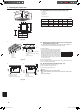
3. Installing the indoor unit (mm) 3.2. Unit dimension and service space (Fig. 3-2) A Air intake B Air outlet C Service space D Drain pan E Electrical parts box (mm) 200 200 11 21 11 Models W H D A B RP71 785 690 428 650 690 RP100 1055 690 428 920 960 RP125, RP140 1415 690 428 1306 1346 *B : Suspension bolt pitch 100 600 300 530 900 Fig. 3-2 1 3.3. Suspension structure (Give site of suspension strong structure) (Fig.
4. Installing the refrigerant piping 4.1. Precautions For devices that use R410A refrigerant • Use ester oil, ether oil, alkylbenzene oil (small amount) as the refrigeration oil applied to the flared sections. • Use C1220 copper phosphorus, for copper and copper alloy seamless pipes, to connect the refrigerant pipes. Use refrigerant pipes with the thicknesses specified in the table to the below.
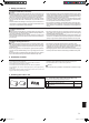
4. Installing the refrigerant piping 4.3. Refrigerant and drainage piping locations of indoor unit (Fig. 4-3) A Refrigerant pipe (gas) B Refrigerant pipe (liquid) C Drain pipe D Air filter (option) E Ceiling Fig. 4-3 4.4. Refrigerant piping (Fig. 4-4) A Refrigerant pipe and insulating material Fig.
6. Electrical work 6.2. Indoor unit power supplied from outdoor unit The following connection patterns are available. The outdoor unit power supply patterns vary on models.
6. Electrical work 6.3. Separate indoor unit/outdoor unit power supplies (For PUHZ application only) The following connection patterns are available. The outdoor unit power supply patterns vary on models. 1:1 System * The indoor power supply terminal kit is required.
6. Electrical work 6.4. For wired remote controller (Optional parts) 30 1) Installing procedures (1) Select an installing position for the remote controller. (Fig. 6-4) The temperature sensors are located on both remote controller and indoor unit.
6. Electrical work Select unit numbers 01 to 03 or all units (AL [wired remote controller]/07 [wireless remote controller]) Mode Filter sign Settings 100Hr *1 2500Hr *1 No filter sign indicator Mode no. 07 Setting no 1 2 3 Initial setting setting *1. The functions below are available only when the wired remote controller is used. 7. Duct work (Fig.
8. Test run A ON/OFF button B Test run display C Indoor temperature liquid line temperature display D ON/OFF lamp E Power display F Error code display Test run remaining time display G Set temperature button H Mode selection button I Fan speed button M TEST button 8.2. Test run The following 2 methods are available. 8.2.1. Using wired remote controller (Fig. 8-1) 1 Turn on the power at least 12 hours before the test run. 2 Press the [TEST] button twice.
8. Test run [Output pattern B] Errors detected by unit other than indoor unit (outdoor unit, etc.
9. Easy maintenance function Display example (Comp discharge temperature 64 °C) By using the maintenance mode, you can display many types of maintenance data on the remote controller such as the heat exchanger temperature and compressor current consumption for the indoor and outdoor units. This function can be used whether the air conditioner is operating or not. During air conditioner operation, data can be checked during either normal operation or maintenance mode stable operation.
A4-tombo-blank.
A4-tombo-blank.
This product is designed and intended for use in the residential, commercial and light-industrial environment. The product at hand is based on the following EU regulations: • Low Voltage Directive 2006/95/ EC • Electromagnetic Compatibility Directive 2004/108/EC Please be sure to put the contact address/telephone number on this manual before handing it to the customer. HEAD OFFICE: TOKYO BLDG., 2-7-3, MARUNOUCHI, CHIYODA-KU, TOKYO 100-8310, JAPAN RG79D318H02 RG79D318H02_cover.